Transcription
Acorn CNC12Macro ProgrammingIntroduction to Centroid Acorn CNC12 MacrosCNC Software version: CNC12 V.4.20 Models: Acorn CNCWhat is a Macro?1What is a User Variable?6How to Interact with an Input?4What is a Parameter?5Using “IF THEN ELSE”12Block Numbers and GOTO Command12How to interact with an Output13Creating Custom Operator Prompt Messages16Skip Graphing, Skip Searching16Rack Mount ATC Macro Example19FAQ’s21Acorn CNC12 Machine Configuration parameters32intro to centroid cnc macros.pdf rev 23 12-17-19
Introduction to Centroid CNC MacrosWhat is a Macro?A Macro used to describe a set of CNC control commands that are called upon to perform a machine tool function, think ofit as a bundle of commands that you can use at the touch of a button or by adding a single M code into a G&M code program. The word macro is a term is being loosely used here to cover a wide variety of CNC “programs”, everything from amachine tool homing program to an automatic tool change program. Macros are simply G and M code programs, they canbe one line or thousands of lines. Most all CNC12 G&M codes can be used in a macro. There are many stock ‘macros’included with CNC12. CNC12’s included “M-Functions” are used to perform specialized actions in CNC programs. Most ofthe CNC12 M-Functions have default actions as described in the Mill and Lathe operators manuals, but can also be customized with the use of macro files.How do I create or edit a Macro?A macro program is just a text file like any other G and M code program. We recommend using Notepad (not Notepad).Notepad is a free powerful text editor and can be downloaded for free here.https://notepad-plus-plus.org/downloads/Where to Start?There are included “stock” macros with the Acorn CNC12 software installation. Many of these macros have instructionsand comments built into them so they can be user modified and also used as macro programming learning examples.Most macros end with the .mac file extension with some exceptions for special cases such as the home program fileswhich are “cncm.hom” and “cnct.hom”.The most common Acorn CNC macros for beginners to edit and modify are: Machine Tool Homing Macro: cncm.hom (mill or router) or cnct.hom (lathe)Machine Tool Parking Macro: park.macMacros that are preassigned to the VCP Aux keys 8,9,10,11: M55(Aux 8),M56 (Aux 9),M57(Aux 10),M58 (Aux 11)Macros that are preassigned to the Wireless MPG Macro keys 1-4: Plcmacro1(2,3,4).macThe Home macro is created by the Acorn Wizard based on the selections made in the Wizard for the type of homing, direction of homing, order of homing. Most Acorn users will not have to edit the Home macro as the Wizard does a goodjob creating home macros (aka home programs). However there are a cases where it is nice to add some customizationto the home program to make the work flow on a machine tool better.The pre-assigned Macros for the VCP aux keys and the MPG Macro buttons are themselves commented with examples.Once you have Acorn up and running and homed, Press the VCP Aux 8 key (that will run the M55 macro) and the instructions on how to edit M55 appear on the screen (and same with the Wireless MPG Macro 1,2,3,4 buttons). The M-codeM55 calls and runs the commands contained in the text file “mfunc55.mac. Opening, studying and modifying these existing macro is a great place to start.The included macros are located in these directories “cncm”, “cnct”, “cncm/system” and “cnct/system”.Edit your first macro!Below is a typical Wizard generated Acorn Home Program for a three axis milling machine.M91/Z L1M26/ZM92/Y L1M26/YM91/X L1M26/X; move Z axis in negative direction seeking home switch, trigger switch and then reverse to clear switch; set Z home at current position; move Y axis in positive direction seeking home switch, trigger switch and then reverse to clear switch; set Y home at current position; move X axis in negative direction seeking home switch, trigger switch and then reverse to clear switch; set X home at current positionLets say we want to set the Z axis Home position .050” away from the Z home switch rather than right after the switchclears and do this automatically.1
Open “cncm.hom” with Notepad and insert the line shown highlighted belowM91/Z L1G91 Z .050 F25M26/ZM92/Y L1M26/YM91/X L1M26/X; move Z axis in negative direction seeking home switch, trigger switch and then reverse to clear switch; move Z axis incrementally in the positive direction .050”; set Z home at current position; move Y axis in positive direction seeking home switch, trigger switch and then reverse to clear switch; set Y home at current position; move X axis in negative direction seeking home switch, trigger switch and then reverse to clear switch; set X home at current positionUsing Notepad save the file (File, Save). Now the next time you home the machine (or press reset home on the VCP)the machine, after clearing the Z home switch, will back away from the Z home switch an additional .050” before settingthe Z home position at the current location. See Operators manual G and M code chapters for description of M26, M91/2and G91Edit your second macro! Lets edit M55 so that it will Rapid move to the XY position X 0, Y 0.M55 is a stock Acorn macro that is preassigned to the VCP (Virtual Control Panel) Auxiliary key #8 so when you press Aux8 CNC12 will execute the commands contained within M55. Lets edit M55 so that it will rapid move the machine to WCSX 0, Y 0. Open mfunc55.mac with Notepad . Note: A semi colon ";" tells CNC12 that the line is a comment, removesemi colon for command to be run, add semi colon to beginning of line to be ------------------------------------; Filename: mfunc55.mac - To run from VCP AUX 8 key, set p195 5511; M55 macro; Description: User Customizable Macro; Notes:; Requires: Machine home must be set prior to use.; Please see TB300 for tips on writing custom -----------------------------------IF #50001;Prevent G code lookahead from parsing past hereIF #4201 #4202 THEN GOTO 1000 ;Skip macro if graphing or searchingM225 #100 "This is an example macro named mfunc55.mac and can be found in .\cncm or .\cnct\nEdit it to include the desired functionality.Press Cycle Cancel/ESC to Exit"N100;Insert your code between N100 and N1000; Insert commands here.N1000;End of MacroPlace a semi colon in front of the M225 line to comment it out, and then insert your custom G and M codes in betweenlines N100 and N1000.So, to modify M55 to Rapid X and Y axis to the position X0, Y0 to look like this:; M225 #100 "This is an example macro named mfunc55.mac and can be found in .\cncm or .\cnct\ .etc.;N100G0X0Y0N1000;Insert your code between N100 and N1000; G0 Rapid Move to position X 0, Y 0 in the current Work Coordinate System;End of MacroUsing Notepad save the changes to mfunc55.mac using File, then Save. Now in CNC12 the machine tool will rapid to the XY position 0,0 when Aux 8 is pressed or when a M55 is contained in a G and M code program.2
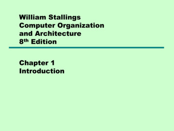
Edit your third Macro!Park.mac is a Machine Tool Parking macro that is primarily used to park a machine at the end of the day. Typical use of aPark macro will move the machine close to the home switches so that the machine is ready to run the home macro in themorning with minimum of movement. CNC12 has default Parking functionality built into it so, if the Acorn Wizard is set toNo as seen below then then the default CNC12 park action is used.The default action is fine for most average milling machines but, I find that most users will benefit from editing and creating a custom Park macro to suit their particular machine tool and application. The default action will Rapid Move the axesclose the to home switches. A common custom Park.mac will move the axis close to the home switches but at a userspecified feedrate.Choose “Yes” to override the default park behavior and edit “park.mac”3
The stock Park.mac macro looks like this below, there are three examples given that are commented out with a semi ----------------------------------; Filename: park.mac - Custom Park Button Macro; Description: This Machine Park macro controls the "F1 Park" command action found in the CNC12 "F10 Shut Down" menu.; park.mac is a user editable custom macro used for parking a machine tool at a specified position at a specified speed, typically used prior to shut down.; Notes:; - This macro overrides the default CNC12 park behavior logic when selected to do so in the Wizard (the Wizard sets CNC12 parameter 59 1); - This macro allows the user to customize the action and behavior of the "Park" feature in the CNC12 "Shut Down" menu by writing creating a custom G&M code program; - A semi colon ";" tells CNC12 that the line is a comment, remove semi colon for command to be run, add semi colon to beginning of line to be ------------------------------------M225 #100 "Please edit c:\cncm\system\park.mac to create a custom parking macro, press ESC to ----------------------------------; Example Custom Mill Park Macro assuming XYZ home position is set in the negative direction for each axis.;G53 Z.25 L20 (Moves Z axis first in machine coordinates to .25 inches away from Z home position at 20 inches per minute);G53 X1 L200 (Moves X axis second in machine coordinates to 1 inch away from X home position);G53 Y1 L200 (Moves Y axis third in machine coordinates to 1 inch away from Y home -------------------------------------; Example Custom Park Macro assuming Y home position is set in positive direction and XZ home position is set in the negative direction for each axis.;G53 Z.25 L20 (Moves Z axis first in machine coordinates to .25 inches away from Z home position at 20 inches per minute);G53 X1 L200 (Moves X axis second in machine coordinates to 1 inch away from X home position at 200 inches per minute);G53 Y-1 L800 (Moves Y axis third in machine coordinates to 1 inch away from Y home position at 800 inches per -----------------------------------; Example Custom Park Macro assuming Y home position is set in positive direction and XZ home position is set in the negative direction for each axis.;G53 Z.25 L20 (Moves Z axis first in machine coordinates to .25 inches away from Z home position at 20 inches per minute);G53 X1 Y-1 L200 (Moves X and Y axis at the same time in machine coordinates to 1 inch away from X home position at 200 inches per minute);G53 w0 L360 (Moves W rotary axis in machine coordinates to 0.000 at 360 degrees per ------------------------------------To customize Park.mac, Add a semi colon in front of the M225 line to comment it out.And then uncomment one of the examples provided and edit the feedrate and direction to your requirements. Seechanges highlighted in yellow ----------------------------------; Filename: park.mac - Custom Park Button Macro; Description: This Machine Park macro controls the "F1 Park" command action found in the CNC12 "F10 Shut Down" menu.; park.mac is a user editable custom macro used for parking a machine tool at a specified position at a specified speed, typically used prior to shut down.; Notes:; - This macro overrides the default CNC12 park behavior logic when selected to do so in the Wizard (the Wizard sets CNC12 parameter 59 1); - This macro allows the user to customize the action and behavior of the "Park" feature in the CNC12 "Shut Down" menu by writing creating a custom G&M code program; - A semi colon ";" tells CNC12 that the line is a comment, remove semi colon for command to be run, add semi colon to beginning of line to be ------------------------------------;M225 #100 "Please edit c:\cncm\system\park.mac to create a custom parking macro, press ESC to ----------------------------------; Example Custom Mill Park Macro assuming XYZ home position is set in the negative direction for each axis.;G53 Z.25 L20 (Moves Z axis first in machine coordinates to .25 inches away from Z home position at 20 inches per minute);G53 X1 L200 (Moves X axis second in machine coordinates to 1 inch away from X home position);G53 Y1 L200 (Moves Y axis third in machine coordinates to 1 inch away from Y home -------------------------------------; Example Custom Park Macro assuming Y home position is set in positive direction and XZ home position is set in the negative direction for each axis.;G53 Z.25 L20 (Moves Z axis first in machine coordinates to .25 inches away from Z home position at 20 inches per minute);G53 X1 L200 (Moves X axis second in machine coordinates to 1 inch away from X home position at 200 inches per minute);G53 Y-1 L800 (Moves Y axis third in machine coordinates to 1 inch away from Y home position at 800 inches per -----------------------------------; Example Custom Park Macro assuming Y home position is set in positive direction and XZ home position is set in the negative direction for each axis.G53 Z.25 L20 (Moves Z axis first in machine coordinates to .25 inches away from Z home position at 20 inches per minute)G53 X1 Y-1 L200 (Moves X and Y axis at the same time in machine coordinates to 1 inch away from X home position at 200 inches per minute)G53 w0 L360 (Moves W rotary axis in machine coordinates to 0.000 at 360 degrees per ------------------------------------Using Notepad save the changes to park.mac using File, then Save. Now in CNC12 the Park feature found in the ShutDown menu will run this custom macro and in the example above will move Z slowly .25” from Z home and then move Xand Y simultaneously to 1” away from machine home position and then moves the rotary axis to the W0 machine position.See Operators manual G and M code chapters for description of G53 and M225 and FAQ section below for description of“L” command.Tip: If you built your own CNCPC edit the Windows file extension default application settings so Notepad will be the default editor for .mac, .hom, .cnc, .nc, .txt4
The mill (and lathe) operator manual has a number of sections covering macro programming.Once you are familiar with a basic macros such as mfunc55.mac, cncm/t.hom and park.mac you can start to increaseyour macro knowledge by reading the related macro material in the CNC12 Operators Manuals:CNC12 Mill Operator Manual (manuals can be found here. https://www.centroidcnc.com/centroid diy/centroid manuals.html )Chapter 11: CNC program codespage 193Chapter 13: CNC program M codespage 243G65Call Macropage 222M98/99Call Subprogrampage 251M100/M101Wait for PLC bitpage 253M200/223,224,225,290 Formatted Stringpage 260Advanced Macro Statementspage 202Chapter 14 covers stock ATC macrospage 265Acorn Wizard canned PLC functions and M Codes.https://www.centroidcnc.com/centroid diy/downloads/acorn documentation/acorn wizard input output plc functions.pdfAnd be sure to visit these two threads on the Acorn CNC Tech Support Forum for free downloads of custom macros forAutoTool Setting and ATC’s. “Tool Setting Options For Routers and Mills” and “Acorn ATC Overview” in the “Acorn CNCTech Tips Knowledge Base” forum.Other Related useful Reference Material: Centroid CNC12 PLC Programming Manual (https://www.centroidcnc.com/centroid diy/centroid manuals.html )Centroid PLC Programming Videos on the Centroid CNC Tech support YouTube Channelhttps://www.youtube.com/playlist?list PLXhs2C5No0 gFS RmKNo7hii2WKIedQlQPLC detective https://www.centroidcnc.com/downloads/centroid PLC detective quickstart.pdfCNC Services Northwest’s web page: Advanced CNC Macro Programming Tips and Techniques for CentroidControls. Common Uses of MacrosMachine tool Homing, Machine tool parking, custom Probing, Rack Mount tool changers the possibilities are endless.Limitations of Macros:Macros inherit the same limitations as when running G&M programs in MDI or running a job file. One such limitation isthat macros require supporting PLC code to directly interact with outputs. Macros can read the states of inputs, outputs,and memory with the m100 and m101 command. Supporting PLC code is required for a macro to toggle an output usingthe m94 and m95 commands as seen in the examples below.5
What is a User Variable?:Think of a variable as a memory location that you get to use for any purpose in your macro. Just like you would writedown a measurement or other number to record it in a notebook to remember it and use it at a later time a User Variableis commonly used this way in a custom macro. There are two types of user variables, volatile and nonvolatile, which aredefined as variable numbers 100-149 and150-159 respectively. The value of a volatile variable as the name implies will be“erased” after the macro is finished or a power cycle. The value of a non-volatile variable will be retained after the macro isfinished and through a power cycle this makes nonvolatile user variables useful in certain applications such as keepingtrack of what tool is in the spindle in a custom ATC macro. Throughout this document we will be assigning these user variables 100-149 and 150-159 values in the examples given. User variables are different from system variables (describedbelow) in that they do not have interaction with any stock CNC12 function hence the name “User Variable” therefore bydefinition variable #’s 100-149 and 150-159 will have no conflict with the standard feature set of CNC12.Commonly Used Expressions in Macros: (see the entire list Mill Chapter 11.2.14) Equals (or “eq”) Logical Not!(or “not”) Logical and&& Logical or Greater than (or “gt”) Less than (or “lt”)How to Read and Write to a User Variable:Macros can be used to both read values and write to some system variables in the control software. Common systemvariables used are user variables numbers: #100-149, non-volatile user variables numbers: #150-159 and the Tool Number indicator (#4120)Referencing the Manuals, a variable can be read by a macro if it has an “R” in the R\W column of the chart.If a variable has a “W” then the macro can also write to this value.#100 1#101 1 1#103 [1 #100 #101]#150 #4120; writes the value of 1 to the user variable #100; writes the value of 2 to the user variable #101; writes the value of 4 to the user variable #103; sets user variable 150 to equal the value of the Requested Tool Number *see note below#4120 is the CNC12 System Variable number for the Tool Number requested by the T command. For example if you entered T9 into MDI, the software sets #4120 to the value of 9. A common use of setting a user variable equal to #4120 isthis allows the author of a macro to use the current tool number in a custom m6 ATC macro for tool changes. This line isused to keep track of which tool is currently in the spindle. Examples of this are presented later in this document.* Note: The line: “#150 #4120” needs an important “IF #50001” to accompany it and is explained later in this document.What is a System Variable?A system variable is a memory location contained in CNC12 defined by a number. System variables reference values, settings, and words found in the CNC12 software. Some of the most commonly used system variables in macros are 9000 to9999 which represent CNC12 system parameters 0 to 999. These are the same parameters that you can see in the parameter menu (F1 Setup, F3 Config, F3 Params) in CNC12, however when we want to reference these parameters in themacro, we use the system variable that represent the parameter.Refer to mill operators manual 11.2.16 or lathe operators manual 9.2.15 for full list of CNC12 system variables.6
How to interact with an InputInputs can be interacted with using M100/M101, M105/M106 or IF statements. M100/M101 commands simply look for theinput while M105/M106 moves an axis in the minus or plus direction looking for the input and the IF statements will lookfor if the expression is true or not.Example 1: Set current WCS X 0.0000 when input 1 turns off (a Home Switch for example)N100M105 /X P1 F30G92 X0N1000;M105 Move In Minus Direction, /X Move X axis, P1 Look at Input 1 to Open,;F30 Move at 30” /min (Based on CNC settings, might be 30mm /min if set to metric);G92 Set Absolute Position for WCS, X0 Sets X-axis to zeroExample 2: Set current Machine X 0.0000 when input 1 turns off (a Home Switch for example)N100M105 /X P1 F30M26 /X;M105 Move In Minus Direction, /X Move X axis, P1 Look at Input 1 to Open,;F30 Move at 30” /min (Based on CNC settings, might be 30mm /min if set to metric);G26 Set Axis Machine Home, /X Sets home for the X-axis;Sets Machine Coordinates X-axis to zeroN1000Example 3: Look for an input to be closed (on) before continuing the macro:;Note: Input 3 has been defined as “Tool is Unclamped” using the Acorn Wizard.;N100;Block 100 (start of macro)M15;Unclamp tool, M15 is a macro that activates the tool unclamp outputM101 /50003;Wait for input 3 to close (turn on) to verify that the ATC spindle has actually unclampled the tool; .the macro continues on when it sees input 3 has been made!Example 4: Stop and Wait for operator with message.In this example below a message will be displayed for the operator until the cycle start button is pressed.;Note: Input 3 has been set to “Tool is Unclamped” using the Acorn Wizard, typically a ATC spindle sensor is used;#100 0;Sets user variable #100 (#100 is being used to set a timer for how long the Message will be displayed;a value of 0 means the message will display until user presses cycle start.; Use M225 to stop, issue message and look for input;IF !#50003 THEN M225 #100 “Tool in Spindle, Remove and press cycle start”;;If Input 3 is Open (off), Then display the message and wait for operator to press start to continue;(See Mill Chapter 13.55 for more info on M225)M225 is the display formatted string for a period of time command. In the example above, #100 is a user variable that defines the time the message will display. If a m225 command is given a zero time, it will display the message indefinitely7
waiting for the cycle start key to be pressed, otherwise it will wait the amount of time specified then will continue with themacro.Alternatively, an M00 or M01 can be used if you desire no message and for the macro to simply wait for the operator to hitcycle start. Useful for situations where the need to check over the machine during a particular part of a macro or job is required.Example 5: Unlike Outputs, Inputs do not have to be defined in the PLC program for a macro to use them. Also, an inputthat is defined in the PLC program can be used by the macro not only for the intended purpose of the input but also forother functions.For instance: Assume Input 3 is left unused in the Acorn Wizard but a Surface Plate is wired to input 3, a macro can still“see” input 3 and react to its state.M115 /Z P3 F20M116 /Z P3 F10M115 /Z P3 F5G92 Z.5G4 P.5G53 Z.5;Move at fast probing rate until Surface Plate is detected;Retract at 10 ipm feedrate until Surface Plate clears;Move at 5 ipm feedrate until Surface Plate detected;Set Z position to Surface Height Thickness (sets Z 0 at top of work or spoil board);Wait half a second;Retract Z to .5 in machine coordinates, (.5 away from Z home position)Now, assume Input 3 is defined in the Acorn Wizard as “ToolTouchOffTriggered” AND a Surface Plate is also wired to thesame input 3. The very same macro above can be used. It is interesting to note that a macro can “look” for a SurfacePlate Detector which is also wired into the same input at the TT device saving on inputs necessary to have both SurfacePlate and Tool Touch off functionality. Just keep in mind that any stock functionality of the Input assignment made in theWizard (like the tool touch off messages and probe protection) will be enabled for that input, even though the macro is notintended to used input 3 as a Tool Touch Off.8
What is a parameter?CNC12 control configuration parameters are used to configure CNC12 to meet the CNC requirements of a particular machine tool, these parameters allow access to hard coded CNC functionality within CNC12 and allow the integrator tochoose and fine tune certain aspects of CNC12 software. See the Mill Operator Manual Chapter 15.3 and the Lathe Operator Manual chapter 12.3 for details on the standard CNC12 parameters. You will notice that there are a large number ofbuilt-in functions and configurations CNC12 that are controlled by the CNC12 parameters. These parameters allow theuser/integrator to pick and choose how they would like the CNC control to act or appear by editing the parameter valuesto select the choice or functionality they desire. For instance if we would like the CNC12 User Interface language to display in German. Set Parameter #9 value 5, press F10 to save and bingo, CNC12 is in German.Typically most Acorn users will never have to edit or change a CNC12 control configuration Parameter as the Wizard setsmost all the Acorn the related parameters for you. But there are cases where Acorn users would have to edit a CNC12parameter manually (such as the Language example above), when installing an ATC and a few special cases when it isdesirable to edit a parameter with a Macro. A common example of this is M74, the Auto Squaring macro. In this macroParameter 967 is edited by the M74 macro to un-pair and then re-pair the two motors on a moving gantry so independentmovement can be achieved to align the two sides of the gantry to square.Not only are Parameters defined values that represent many different features and settings for use in CNC12 but they canalso be used in conjunction with the PLC program and Macros. With Macros we can read these parameters and also writeto them as described below.When would I use a Parameter instead of a Variable?Typically one would use parameter values instead of user variables in cases where a parameter is already defined withthe value we want to use and/or we want the operator to have the choice to change the value in software.Parameters are similar to Non-volatile user variables where you can store values between jobs or through power cycles,however they can be also edited by the operator easily in the parameters menu in software. F1 Setup, F3 Config, F3ParamThe Acorn version of CNC12 makes use of several new parameters that are not in the CNC12 operators manual. A description of these special Acorn parameters are listed below. ( A description of most of them are also contained in the beginning of the Acorn PLC program source file (.SRC) in the comments section as well).Parameters 700 to 799 are allocated as special use parameters reserved specifically for the CNC12 user/integrator to usein a custom application. This reservation of P700-799 allows the user/integrator to create their own custom parameters inboth Macro and PLC programs and then the user/integrator can be sure that P700-799 will not be used by CNC12 or aCentroid Standard PLC program in the future, this ensure that any custom PLC or Macro made today using P700-799 willnot have a conflict with future CNC12 updates. So, if you need to make a custom parameter use any one in the P700 to799 range.How to read a parameter value.In reference to the system variable chart in the mill or lathe manual, we can find that 9000-9999 are the system variablesfor parameters 0-999. These are the same parameters that you can find in the parameters menu within CNC12 (F1 setup,F3 config, F3 Params). In Macros, it is very simple to read from the system variable parameter values. We will typicallyuse parameter values instead of user variables in cases where a parameter is already defined with the value we want touse and/or we want the operator to have the choice to change the value in software. We simply need to assign a variableto a parameter, for example:#101 #9710;Sets user variable 101 to the value of parameter 710System Variables do not always need to be assigned to a user variable, most often they can be used directly in the logic.G92 Z[#9710];Set WCS Z position to value of Parameter 7109
How to write a parameter value.Referencing the system variables chart in the manual you can read the system variables 9000-9999 (parameters 0-999)as indicated by the R in the R\W column, but we cannot directly write to them as indicated by no “W” in the R\W column.However using the G10 function, a macro can write to these system variables. An example:#103 5G10 P710 R[#103];Sets User variable to value of 5;Sets Parameter 710 to the value of #103Typically in macros we will reference values via system variables, however functions such as G10 only requires the parameter number, and does not use the system variable that corresponds to said parameter. Trying to write to a read onlyvariable will result in an error being displayed in the software when trying to run the macro, examples of some caseswhere this error will appear.NOT ALLOWED:#9710 #101#4120 5;This cannot be done, #9710 cannot be directly written to, only read.;This cannot be done, #4120 is a read only variable, 4120 value is set/changed by CNC12To reiterate, the above is strictly not allowed in this format, but parameter 710 can be written to using the G10 command.G10 P710 R3;Sets parameter 710 to the value of 3Similarly, #4120 can be written to by using the T command,T10;Sets current tool to tool 10, Really this sets #4120 to the value of 10.There are Parameters that are considered “machine setup” related a
CNC Software version: CNC12 V.4.20 Models: Acorn CNC 6 4 What is a User Variable? How to Interact with an Input? Acorn CNC12 Macro Programming What is a Macro? 1 What is a Parameter? 5 Using “IF THEN ELSE” 12 Block Numbers and GOTO Command 12 How to interact with an Output 13 intro_to_centroid_