Transcription
Transformer ProtectionApplication Guide
About the AuthorGeorge Rockefeller is President of Rockefeller Associates, Inc. He has a BS in EE from Lehigh University,a MS from New Jersey Institute of Technology, and a MBA from Fairleigh DickinsonUniversity. Mr. Rockefeller is a Fellow of IEEE and Past Chairman of IEEE Power Systems RelayingCommittee. He holds nine U.S. Patents and is co-author of Applied Protective Relaying (1st Edition).Mr. Rockefeller worked for Westinghouse Electric Corporation for twenty-one years in application andsystem design of protective relaying systems. He worked for Consolidated Edison Company for ten yearsas a System Engineer. He has also served as a private consultant since 1982.About the GuideThis guide contains a summary of information for the protection of various types of electrical equipment.Neither Basler Electric Company nor anyone acting on its behalf makes any warranty or representation,express or implied, as to the accuracy or completeness of the information contained herein, nor assumesany responsibility or liability for the use or consequences of use of any of this information.Original issue date 05/96Revised 05/99, John Boyle; small updatesRevised 08/03, Larry Lawhead; small updatesRevised 04/07, John Horak; extensive rewriteRevised 06/07, John Horak; minor typographical and editorial corrections
Transformer ProtectionApplication GuideThis guide focuses primarily on application ofprotective relays for the protection of powertransformers, with an emphasis on the mostprevalent protection schemes and transformers.Principles are emphasized. Setting proceduresare only discussed in a general nature in thematerial to follow. Refer to specific instructionmanuals for your relay. The references provide asource for additional theory and applicationguidance. An overall view of the economic impact of atransformer failure and what can be done toreduce the risk, including:· The direct economic impact of repairingor replacing the transformer.· The indirect economic impact due toproduction loss.· Repair time vs. complete replacementtime.· The availability of backup power feed oremergency replacement transformers, andthe cost of each option.· The possibility that a given protectionscheme can reduce the damage andresultant repair time, or that it can changea replacement into a repair.The engineer must balance the expense ofapplying a particular protection scheme againstthe consequences of relying on other protectionor sacrificing the transformer. Allowing a protracted fault would increase the damage to thetransformer and the possibility of tank rupturewith a consequent oil fire and consequentpersonnel safety risks. There is no rule that sayswhat specific protection scheme is appropriatefor a given transformer application. There issome tendency to tie protection schemes to theMVA and primary kV of a transformer. Whilethere is some validity to this approach, there aremany other issues to be considered. Issues tobe considered include:Some specific applications that affect protectionare: A tap changer flashover can ordinarily berepaired in the field, but if this fault is allowed toevolve into a winding fault, the transformer willneed to be shipped to a repair facility; hence,protection that can rapidly sense a tap changefault is desirable. A high magnitude through fault(external fault fed by the transformer) shakes andheats a transformer winding, and the longer thethrough fault lasts, the greater the risk of itevolving into an internal transformer fault; hence,fast clearing for close-in external faults is part ofthe transformer protection scheme. Sometransformers are considered disposable andreadily replaced, reducing the need for advanced protection schemes. Transformer protection commonly includes some coverage of The severity of personnel safety concernsand the possibility that a given protectionscheme can reduce these risks. The danger to nearby structures and processes if a transformer fails catastrophicallyand the possibility that a given protectionscheme can reduce the possibility of such afailure.1
external bus and cable, and faults in these zonesmay expose personnel to arc flash hazards. Slowclearing protection schemes may be unacceptable from an arc flash exposure perspective.Fires in an indoor transformer may have high riskof catastrophic facility damage and even higherpersonnel safety risks, increasing the need foradvanced high speed protection. The proximityof flammable process chemicals increases aneed for protection schemes that reduce the riskof a tank fire. The failure of a transformer used ina large base load unit-connected generator maycause extended generation-replacement costs;even the loss of a small station service transformer can cause a notable disruption of generation and high economic consequences. Similareconomic impacts may also exist at industrialsites. Some transformers are custom designsthat may have long lead times, increasing theneed for advanced protection schemes.2. Protection Example and General ConceptsThe reader interested in additional information,advanced or unusual application advice, anddetailed settings guidance should refer to Ref. 1.This document includes extensive references andbibliographies. Also, Ref. 2 and 3, textbooks onprotective relaying, contain chapters on transformer protection, and Ref. 4, another IEEEstandard, includes good overall protectionschemes where a transformer is the interfacepoint between a utility and an industrial customer.There are three general categories of protectiverelay technology that arise in the discussions tofollow: Electromechanical: uses magnetic fluxcreated from current and voltage to createtorques on movable disks and relays, whichis the source of the term “relay.” Usuallysingle device number functionality. Solid State: uses low voltage analog signalscreated from sensed currents and voltages;uses discrete electronics and basic logiccircuits; may contain a basic microprocessorfor logic and some math. Usually single ordual device number functionality. Numeric: a multifunction, programmablelogic relay; digitizes sensed current andvoltage, then calculates an RMS or phasorequivalent value; uses a high-end microprocessor. Usually incorporates many devicenumber functions.All Basler Electric relays are solid state ornumeric.1. Failure StatisticsTable I lists failures for six categories of faults(IEEE C37.90, “Guide for Protective RelayApplications to Power Transformers, Ref. 1).Winding and tap changers account for 70% offailures. Loose connections are included as theinitiating event, as well as insulation failures. Themiscellaneous category includes CT failure,external faults, overloads, and damage inshipment. An undisclosed number of failuresstarts as incipient insulation breakdown problems. These failures can be detected by sophisticated online monitoring devices (e.g. gas-in-oilanalyzer) before a serious event occurs.1955-19651975-19821983-1988NumberPercent ofTotalNumberPercent ofTotalNumberPercent ofTotalWinding failuresTap changer failuresBushing failuresTerminal board failuresCore failuresMiscellaneous Table I - Failure Rates, Ref. 1.2
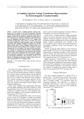
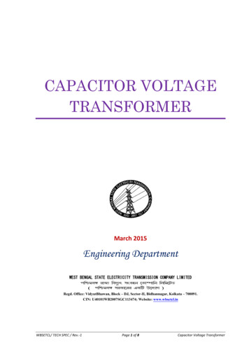
Table II lists some common ANSI device numbers associated with transformer protection. Anumeric relay generally contains many implementations of these devices within its programming, and each instance of a device is referredto, herein, as an “element” in the relay. Forexample, while the Basler BE1-CDS220 isprimarily a transformer differential relay (hence,includes the 87 device in elements named 87Pand 87N), it also includes nine independentimplementations of the 51 overcurrent device,called the 51P, 151P, 251P, 51Q, 151Q, 251Q,51N, 151N, and 251N elements as well as manyother device functions.If there is a possibility of over voltage on theunits due to local generation or a transformerbeing placed at the end of a long line (the“Feranti” effect), voltage relays (24 and 59,Section 4.4.4) may be included. Another possible backup protection scheme is low voltage(27) or unbalanced voltage detection (47). Ifthere is local generation, to help detectislanding conditions an over/under frequency(81, O/U) relay may be installed, though an 81may not be considered a transformer protectionelement.Directional overcurrent relays and directionalpower (67/50, 67/51, and 32, respectively,Section 8.4) respond to load current circulatingthrough the 13 kV buses when the 115kVbreaker A is open and the 13.8kV tie is closed.The elements may also respond to faults in thetransformer near the secondary bushings. If thetransformers can be operated in parallel, theelements also provide a means to sense tapchangers that have become out of step with oneanother. If there is generation in the 13.8kVsystem, sensitive 67 elements can sense a smallgenerator backfeeding a 115kV fault.Figure 1 shows extensive use of relays thatwould be representative of a large industrialload. This will be used for discussions in some ofthe material that follows. There are two 115 kVfeeds to two 30 MVA transformers that areresistance grounded on the 13 kV side, limitingground fault current to about 400A from eachtransformer. In other applications, a reactor isused, and in some applications, the ground faultcurrent is limited to less than 10A. In a typicalutility application, transformers are connecteddirectly to ground, but occasionally a smallreactor is placed in the transformer neutral thatlimits ground fault current to approximately thesame level as three phase faults. In this examplesystem, the protection scheme describedapplies to solidly grounded (as well as impedance grounded) systems, except the effect ofground impedance results in the addition ofprotection functions not required on a solidlygrounded system.The primary and secondary relaying wouldsometimes be configured to feed their ownlockout relays (86) to help ensure that protectionis available even with a failure of one 86 relay orits dc feed.The protection scheme in Fig.1 does not utilizefuses. Fuses normally would be seen only onlower MVA transformers than indicated. SeeSection 3.The phase and ground differential (87P and 87N,Section 4) and sudden pressure relay (63,Section 6) provide the primary transformer faultprotection. The suite of overcurrent elements(51, Section 8) is generally considered backuptransformer protection, or for protection of thebus and backup protection for the feeder relays.These elements are part of the transformerprotection in that they limit the accumulateddamage that occurs from a transformer feedinghigh current into downstream faults. The 67Nrelay offers an alternative to the 87N function.Hot spot monitoring (49, Section 9) is indicated,but is likely an alarm only scheme.Transformers of the indicated MVA normallywould have their oil tested for dissolved gasses(Section 7) as part of routine maintenance.Larger transformers may have continuous on-linemonitoring equipment.Tables III and IV (pages 29-30) provide BaslerElectric relay models and their device numbers.3
Figure 1 - Protection Example4
7Power ElementNegativesequenceovervoltageThermalPhase TimeOvercurrentGround TimeOvercurrent, measuredby dedicated windowCT, or CT ontransformer neutralNeutral TimeOvercurrent 3Io Phase CTResidualNegativeSequence TimeOvercurrentInstantaneousOvercurrent.P, G, N, Q havesame meaning asfor the n59N6367/50x67/51x8687P87U87NSudden PressureDirectional control,directionalinstantaneous,directional timeovercurrentLockout AuxiliaryPhase DifferentialUnrestrainedDifferentialGround DifferentialCommentFor overexcitation detection. Similar to 59 but the pickup is proportionate tofrequency.Typically an inverse time characteristic.ll line to lineln line to neutral (or line to ground. Note neutral may be isolated from ground insome systems.)Used to sense power backfeed through transformerUsually defined by: V2 (Van a2Vbn aVcn)/3. (a 1 120).It is also possible to define V2 in terms of Vll. Some relays define the 47 in terms ofa manufacturer-specific voltage unbalance measurement rather than in terms of V2.Typically top oil temperature RTD.A 51 by itself usually refers to phase time overcurrent, but adding the P givesadditional clarity.Herein: Ground refers to current on a transformer ground/neutral bushing orcurrent from a window CT that wraps all three phases (and possibly also wrapsa neutral bus if one exists).Neutral refers to the phase current summation (In Ia Ib Ic), which is theequation used for 3Io in numeric relays and which is also the summation of the3 phase CTs ("residual").Defined by: I2 (Ia a2Ib aIc)/3In some relays, a 50 has the option of being time delayed; hence, it becomesa definite time element and may be renamed 50TP, 50TG, 50TN, or 50TQ.ll, ln line-line or line to neutral/ground. N refers to V0 or 3V0 sensing, dependingon the manufacturer. V0 (Van Vbn Vcn)/3.There may be separate devices for the tap changer and main tank.x refers to P, G, N, or Q. The 67 by itself is used inconsistently in the industry.Herein, for clarity, a 67 is a sensitive forward/reverse polarizing bit thatcontrols the 50 and 51 element, and the dual term 67/50x or 67/51 is used.Most transformer trips are directed to a lockout relay.Comprised of several functional elements. See text for description. Many variationsby relay and manufacturer.Monitors phase differential. Trips when magnitude is much greater than maximuminrush levels.Sometimes referred to as a "Restricted Earth Fault" sensing element. It is morecommonly applied on systems with impedance in the transformer neutral for thepurpose of limiting ground fault current.Table II - ANSI Device Numbers (C37.2)3. FusesFuses are economical, require little maintenance, and do not need an external powersource to clea
Table II lists some common ANSI device num-bers associated with transformer protection. A numeric relay generally contains many imple- mentations of these devices within its program-ming, and each instance of a device is referred to, herein, as an “element” in the relay. For example, while the Basler BE1-CDS220 is primarily a transformer differential relay (hence, includes the 87 device in .