Transcription
Dell Precision T3500 Service ManualWorking on Your ComputerAdding and Replacing PartsSpecificationsDiagnosticsAbout Your System BoardSystem SetupNotes, Cautions, and WarningsNOTE: A NOTE indicates important information that helps you make better use of your computer.CAUTION: A CAUTION indicates potential damage to hardware or loss of data if instructions are not followed.WARNING: A WARNING indicates a potential for property damage, personal injury, or death.If you purchased a Dell n Series computer, any references in this document to Microsoft Windows operating systems are not applicable.Information in this document is subject to change without notice. 2009 Dell Inc. All rights reserved.Reproduction of this material in any manner whatsoever without the written permission of Dell Inc. is strictly forbidden.Trademarks used in this text: Dell, the DELL logo, and Dell Precision are trademarks of Dell Inc.; Intel and Xeon are registered trademarks of Intel Corporation; Bluetooth is aregistered trademark owned by Bluetooth SIG, Inc. and is used by Dell under license; Blu-ray Disc is a trademark of the Blu-ray Disc Association; Microsoft, Windows, WindowsServer, MS-DOS, Aero, Windows Vista. and the Windows Vista start button are either trademarks or registered trademarks of Microsoft Corporation in the United States and/or othercountries.Other trademarks and trade names may be used in this document to refer to either the entities claiming the marks and names or their products. Dell Inc. disclaims anyproprietary interest in trademarks and trade names other than its own.Model DCTASeptember 2009Rev. A01
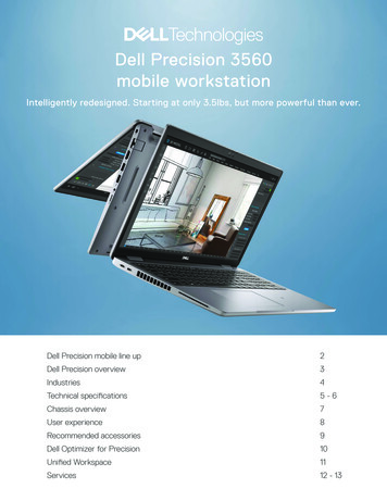
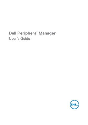
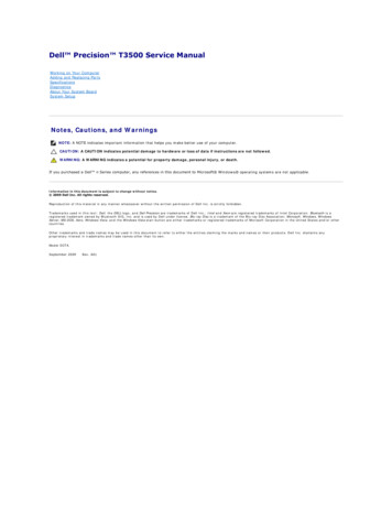
About Your System BoardDell Precision T3500 Service ManualPassword Enable JumperNVRAM Reset JumperSystem Board SchematicWARNING: Before working inside your computer, read the safety information that shipped with your computer. For additional safety bestpractices information, see the Regulatory Compliance Homepage at www.dell.com/regulatory compliance.Your computer's system board offers two jumpers—a password enable jumper and a RTCRST (Real Time Clock Reset) jumper.Password Enable JumperPSWD - Password enable. The system password will be cleared and disabled when the system is started with this jumper removed.Pins 1-2 shorted enables passwordNVRAM Reset JumperRTCRST - Clears NVRAM. The NVRAM will be cleared when the jumper is closed (use the jumper from the password bridge). To properly clear; AC power mustbe applied (not necessarily turned on) to the system for about 10 seconds while the jumper is closed.Pins 1-2 shorted clears NVRAMThe picture below shows the location of the configuration jumpers on the system board.NOTE: You can use the RTCRST jumper procedure above to attempt recovery from a No POST, No Video situation.System Board Schematic
1PCI Card Slot (Slot 6)2PCI Card Slot (Slot 5)3PCIe x16 (Slot 4)4PCIe x4 (Slot 3)5PCIe x16 (Slot 2)6PCIe x4 (Slot 1)7Audio Front Panel (FP AUDIO)8Internal USB (USB 1)9LPC DEBUG10Processor Connector11CPU Power Connector (POWER CPU)12Front Bezel Fan (FAN Front)13Front Cage Fan (FAN CCAG)14Memory Module (RAM) Connectors (DIMM 1-6)15Jumpers (PSWD & RTCRTS)16Battery Socket (CMOS Battery)17Internal USB Socket (for Flexbay Card Reader)18Main Power Connector19SATA Connectors (SATA 0-4)20HDD Fan (FAN HDD)21Serial Connector (SERIAL2)22FDD Connector23Front Panel Connector (FRONTPANEL)24Chassis Intrusion Connector (INTRUDER)
System SetupDell Precision T3500 Service ManualPOST KeystrokesBoot MenuEntering System SetupSystem Setup Navigation KeystrokesPOST KeystrokesYour computer has several keystroke options available during the POST process at the Dell Logo screen.KeystrokeFunctionDescription F2 Enter System SetupUse System Setup to make changes to the user-definable settings. F12 or Ctrl Alt F8 Enter Boot MenuOne-time boot and diagnostics utility menu F3 Network BootBypass the BIOS boot sequence and boot directly to the networkBoot MenuAs with previous Dell Precision workstation platforms, your computer includes a one-time boot menu. This feature offers a quick and convenient method withwhich to bypass the System Setup-defined boot device order and boot directly to a specific device (e.g., floppy, CD-ROM, or hard drive).The boot menu enhancements introduced on previous platforms are as follows:llEasier access—Although the Ctrl Alt F8 keystroke still exists and can be used to call up the menu, you can also simply press F12 duringsystem boot to access the menu.Diagnostics options—The boot menu includes two diagnostic options, IDE Drive Diagnostics (90/90 Hard Drive Diagnostics) and Boot to the UtilityPartition.Entering System SetupPress F2 to enter System Setup and change the user-definable settings. If you have trouble entering System Setup using this key, press F2 when thekeyboard LEDs first flash.Follow the on-screen instructions to view and/or change any settings. On each screen, the system setup options are listed at the left. To the right of eachoption is the setting or value for that option. You can change settings that appear as white type on the screen. Options or values that you cannot change(because they are determined by your Tablet-PC) appear less bright.The upper-right corner of the screen displays help information for the currently highlighted option. The lower-right corner displays information about thecomputer. System setup key functions are listed across the bottom of the screen.The system setup screens display the current setup information and settings for your computer, such as:lllllSystem configurationBoot orderBoot (start-up) configurationBasic device configuration settingsSystem security and hard drive password settingsSystem Setup Navigation KeystrokesUse the following keystrokes to navigate the BIOS screens.Navigation KeystrokesActionKeystrokeExpand and collapse field Enter , left- and right-arrow keys, or /–Expand or collapse all fields Exit BIOS Esc — Remain in Setup, Save/Exit, Discard/ExitChange a settingLeft- and right-arrow keys
Select field to change Enter Cancel a modification Esc Reset defaults Alt F or Load Defaults menu optionNOTE: Depending on your computer and any installed devices, the items listed in this section may or may not appear.
DiagnosticsDell Precision T3500 Service ManualDell DiagnosticsPower Button Light CodesDiagnostic Light CodesBeep CodesDell DiagnosticsWhen to Use the Dell DiagnosticsIt is recommended that you print these procedures before you begin.NOTE: The Dell Diagnostics software works only on Dell computers.NOTE: The Drivers and Utilities disc is optional and may not ship with your computer.Enter system setup (see Entering System Setup), review your computer's configuration information, and ensure that the device you want to test displays inSystem Setup and is active.Start the Dell Diagnostics from either your hard drive or from the Drivers and Utilities disc.Starting the Dell Diagnostics From Your Hard Drive1.Turn on (or restart) your computer.2.When the DELL logo appears, press F12 immediately.NOTE: If you see a message stating that no diagnostics utility partition has been found, run the Dell Diagnostics from your Drivers and Utilities disc.If you wait too long and the operating system logo appears, continue to wait until you see the Microsoft Windows desktop. Then shut downyour computer (see Turning Off Your Computer), and try again.3.When the boot device list appears, highlight Boot to Utility Partition and press Enter .4.When the Dell Diagnostics Main Menu appears, select the test that you want to run.Starting the Dell Diagnostics From the Drivers and Utilities Disc1.Insert the Drivers and Utilities disc.2.Shut down and restart the computer.When the DELL logo appears, press F12 immediately.If you wait too long and the Windows logo appears, continue to wait until you see the Windows desktop. Then shut down your computer and try again.NOTE: The next steps change the boot sequence for one time only. On the next startup, the computer boots according to the devices specified in thesystem setup program.3.When the boot device list appears, highlight Onboard or USB CD-ROM Drive and press Enter .4.Select the Boot from CD-ROM option from the menu that appears and press Enter .5.Type 1 to start the menu and press Enter to proceed.6.Select Run the 32 Bit Dell Diagnostics from the numbered list. If multiple versions are listed, select the version appropriate for your computer.7.When the Dell Diagnostics Main Menu appears, select the test you want to run.Dell Diagnostics Main Menu1.After the Dell Diagnostics loads and the Main Menu screen appears, click the button for the option you want.OptionFunctionExpress Test Performs a quick test of devices. This test typically takes 10 to 20 minutes and requires no interaction on your part. Run Express Test first toincrease the possibility of tracing the problem quickly.ExtendedTestPerforms a thorough check of devices. This test typically takes 1 hour or more and requires you to answer questions periodically.Custom TestTests a specific device. You can customize the tests you want to run.SymptomTreeLists the most common symptoms encountered and allows you to select a test based on the symptom of the problem you are having.2.If a problem is encountered during a test, a message appears with an error code and a description of the problem. Write down the error code andproblem description and follow the instructions on the screen.
3.If you run a test from the Custom Test or Symptom Tree option, click the applicable tab described in the following table for more information.TabFunctionResultsDisplays the results of the test and any error conditions encountered.ErrorsDisplays error conditions encountered, error codes, and the problem description.HelpDescribes the test and may indicate requirements for running the test.Configuration Displays your hardware configuration for the selected device.The Dell Diagnostics obtains configuration information for all devices from system setup, memory, and various internal tests, and it displaysthe information in the device list in the left pane of the screen. The device list may not display the names of all the components installed onyour computer or all devices attached to your computer.ParametersAllows you to customize the test by changing the test settings.4.When the tests are completed, if you are running the Dell Diagnostics from the Drivers and Utilities disc, remove the disc.5.Close the test screen to return to the Main Menu screen. To exit the Dell Diagnostics and restart the computer, close the Main Menu screen.Power Button Light CodesThe power LED located in the power button on the front of the computer illuminates and blinks or remains solid to indicate five different states:lllllNo light—System is in the off state (S5, or mechanical (AC power not applied) OFF).Solid Amber—System fault, but Power Supply is good—normal operating state (S0 ).Blinking Amber—System fault error condition including Power Supply (only 5VSB working), Vreg failure, missing or bad CPU.Blinking Green—System is in power saving states S1, S3 or S4. (Blink rate is 1Hz). No fault/error condition.Solid Green—System is fully functional and is in S0 (ON) state.Diagnostic Light CodesFour (4) single color lights are incorporated on the front control panel to serve as a diagnostic aid for troubleshooting systems exhibiting No Post/No Videosymptoms. The lights do not report runtime errors.Diagnostic LED PatternsLED pattern (1234) LED DescriptionState description1234- Off- Off- Off- OnBIOS checksum failure detected; system is in recovery mode.1234- Off- Off- On- OffPossible processor failure.1234-OffOffOnOnMemory failure.1234-OffOnOffOffPossible expansion card failure.1234-OffOnOffOnPossible video failure.1234-OffOnOnOffDiskette drive or hard drive failure.1234-OffOnOnOnPossible USB failure.1234-OnOffOffOffNo memory modules detected.1234-OnOffOffOnSystem board failure.1234-OnOffOnOffMemory configuration error.
1234-OnOffOnOnPossible system board resource and/or system board hardware failure.1234-OnOnOffOffPossible system resource configuration error.1234-OnOnOnOffOther failure.1234-OnOnOnOnEnd of POST - Hand off to boot.1234-OffOffOffOffThe system is in a normal operating condition after POST.Beep CodesWhen errors occur during a boot routine that cannot be reported on the monitor, the computer may emit a beep code that identifies the problem. The beepcode is a pattern of sounds: for example, one beep followed by a second beep, then followed by a burst of three beeps (code 1-1-3) means that the computerwas unable to read the data in nonvolatile random-access memory (NVRAM). If the system loses power and beeps constantly when you turn it back on, theBIOS is probably corrupted.System Beep U register test in progress2-4-31st 64 K RAM chip or data line failure - bit E1-1-3CMOS read/write test in progress or failure2-4-41st 64 K RAM chip or data line failure - bit F1-1-4BIOS ROM checksum in progress or failure3-1-1Slave DMA register test in progress or failure1-2-1Timer Test in progress or failure3-1-2Master DMA register test in progress or failure1-2-2DMA initialization in progress or failure3-1-3Master IMR test in progress or failure1-2-3DMA page register read/write test inprogress or failure3-1-4Slave IMR test in progress or failure1-3-1RAM refresh verification in progress or failure3-2-2Interrupt vector loading in progress1-3-21st 64 K RAM test in progress or failure3-2-4Keyboard controller test in progress or failure1-3-31st 64 K RAM chip or data line failure (multibit)3-3-1CMOS power fail and checksum test inprogress1-3-41st 64 K RAM odd/even logic failure3-3-2CMOS Config info validation in progress1-4-11st 64 K RAM address line failure3-3-3RTC/Keyboard controller not found1-4-21st 64 K RAM parity test in progress or failure3-3-4Screen memory test in progress or failure1-4-3Fail-safe timer test in progress3-4-1Screen initialization test in progress or failure1-4-4Software NMI port test in progress3-4-2Screen retrace tests test in progress or failure2-1-11st 64 K RAM chip or data line failure - bit 03-4-3Search for video ROM in progress2-1-21st 64 K RAM chip or data line failure - bit 14-2-1Timer tick interrupt test in progress or failure2-1-31st 64 K RAM chip or data line failure - bit 24-2-2Shutdown test in progress or failure2-1-41st 64 K RAM chip or data line failure - bit 34-2-3Gate A20 failure2-2-11st 64 K RAM chip or data line failure - bit 44-2-4Unexpected interrupt in Protected Mode2-2-21st 64 K RAM chip or data line failure - bit 54-3-1RAM test in progress or failure above address0FFFFh2-2-31st 64 K RAM chip or data line failure - bit 64-3-2No memory in Bank 02-2-41st 64 K RAM chip or data line failure - bit 74-3-3Interval Timer Channel 2 test in progress orfailure2-3-11st 64 K RAM chip or data line failure - bit 84-3-4Time-Of-Day Clock test in progress or failure2-3-21st 64 K RAM chip or data line failure - bit 94-4-1Super I/O chip failure2-3-31st 64 K RAM chip or data line failure - bit A4-4-4Cache test failure2-3-41st 64 K RAM chip or data line failure - bit B2-4-11st 64 K RAM chip or data line failure - bit C2-4-21st 64 K RAM chip or data line failure - bit D
Adding and Replacing PartsDell Precision T3500 Service ManualCoverI/O PanelFront BezelPower SupplyHard DriveDrives BezelFloppy DriveOptical DriveMemory Card ReaderMemoryMemory ShroudExpansion CardBatteryChassis Intrusion SwitchVideo CardFan AssemblyHeat Sink and ProcessorSystemboardI/O Data Cable
SpecificationsDell Precision T3500 Service ManualDrivesProcessorsConnectorsSystem InformationControls and pansion BusNOTE: Offerings may vary by region. For more information regarding the configuration ofyour Tablet-PC, click Start(or Start in Windows XP) Help and Support, and thenselect the option to view information about your Tablet-PC.ProcessorProcessor typesIntel Xeon Processor 3500 seriesIntel Xeon Processor 5500 seriesSystem InformationSystem chipsetIntel X58 ICH10Data bus width64 bitsMemoryMemory module connectorsSixMemory module capacities1 GB, 2 GB, or 4 GBMemory typeDDR3 1066 MHz & 1333 MHz (Both ECC and Non-ECC)Minimum memory1 GBMaximum memory24 GBVideoVideo type:DiscreteTwo PCI Express 2.0 x16 slotsNote: Support for discrete full length full heightgraphics option through PCIe x16 graphics card slotAudioAudio typeADI1984A integrated audioExpansion BusBus typePCI 2.3PCI Express 2.0 (PCIe-x16)PCI Express 1.1 (PCIe-x1)SATA 1.0 and 2.0USB 2.0eSATABus speed133 MB/s (PCI)x1-slot bidirectional speed - 500 MB/s (PCI Express)x16-slot bidirectional speed - 8 GB/s (PCI Express)1.5 Gbps and 3.0 Gbps (SATA)480-Mbps high speed, 12-Mbps full speed, 1.2-MbpsLow speed (USB)PCI ConnectorsconnectorsTwoconnector size124 pinsconnector data width (maximum)32 bitsPCI Express x8connectorTwoconnector size98 pinsPCI Express x16connectorTwoconnector size164 pinsDrivesExternally accessibleOne 3.5-inch drive bay (FlexBay), Two 5.25-inch drivebaysInternally accessibleTwo 3.5-inch SATA drive bays
Note: The platform can accommodate third and fourth3.5-inch hard drives in the flex bay or the optical drivebay. (4 HDD support is limited to SATA only & towerorientation only, SAS is limited to 3 HDD)Available devices3.5-inch SATA hard drivesSATA DVD, SATA CD-RW/DVD Combo, SATA DVD /-RW,SATA BD Combo (Blu-Ray playback only), SATA Blu-rayR/WOne 3.5-inch USB media card reader with Bluetooth Internal USB floppy driveConnectorsExternal connectors:VideoNetwork adapter(Depending on video card)DVI connectorDisplay portRJ-45 connectorUSBUSB 2.0 compliant, support 2.0 A sustained charge topower external USB devicesTwo internal connectorsTwo in frontSix at the backAudioTwo rear connectors for line-in and line-outTwo front-panel connectors for headphones andmicrophoneSerialOne 9-pin connectors; 16550C-compatiblePS/2Two 6-pin mini-DIN connectorIEEE 1394aOne front-panel 6-pin connector (with optional card)System board connectors:Serial ATAInternal USB deviceSeven 7-pin connectorsOne 10-pin connectorProcessor fanOne 4-pin connectorChassis fanOne 3-pin connectorHDD cage fanOne 3-pin connectorPCI 2.3Two 124-pin connectorsPCI Express x8Two 98-pin connectorPCI Express x16Two 164-pin connectorFront panel control (USB included)One 40-pin connectorFront panel audio HDA headerOne 10-pin connectorProcessorOne 1366-pin connectorMemorySix 240-pin connectorsProcessor PowerOne 8-pin connectorPowerOne 24-pin connectorControls and LightsFront of the computer:Power buttonPower lightPush buttonAmber light . Solid amber indicates a problem with aninstalled device; blinking amber indicates an internalpower problem.Green light . Blinking green in sleep state; solid green forpower-on state.
Drive activity lightGreen light . A blinking green light indicates the computeris reading data from or writing data to the SATA harddrive or CD/DVD.Network link lightGreen light . Solid green indicates a connection to anactive networkOff (no light) . System is not connected to a networkBack of the computer:Link integrity light (on integratednetwork adapter)Network activity light (on integratednetwork adapter)Green . A good connection at 10Mbs exists between thenetwork and the computer.Orange . A good connection at 100Mbs exists betweenthe network and the computer.Yellow . A good connection at 1000Mbs exists betweenthe network and the computer.Off . The computer is not detecting a physical connectionto the network.Yellow blinking lightPowerDC power supply:WattageMaximum heat dissipation (MHD)VoltageCoin-cell battery525 W1194 BTU/hr115/230 VAC, 50/60 Hz, 6.0/3.0 A3 V CR2032 lithium coin cellPhysicalHeight44.8 cm (17.6 inches)Width17.2 cm (6.8 inches)Depth46.8 cm (18.4 inches)Weight17.3 kg (38.0 lb)EnvironmentalTemperature range:Operating10 to 35 C (50 to 95 F)Storage-40 to 65 C (-40 to 149 F)Relative humidity (maximum):20% to 80% (noncondensing)Maximum vibration (using a random-vibrationspectrum that simulates user environment):Operating5 to 350 Hz at 0.0002 G²/HzStorage5 to 500 Hz at 0.001 to 0.01 G²/HzMaximum shock (measured with hard drive in headparked position and a 2-ms half-sine pulse):Operating40 G /- 5% with pulse duration of 2 msec /- 10%(equivalent to 51 cm/sec [20 in/sec])Storage105 G /- 5% with pulse duration of 2 msec /- 10%(equivalent to 127 cm/sec [50 in/sec])Altitude (maximum):Operating-15.2 to 3048 m (-50 to 10,000 ft)Storage-15.2 to 10,668 m (-50 to 35,000 ft)Airborne contaminant levelG2 or lower as defined by ISA-S71.04-1985
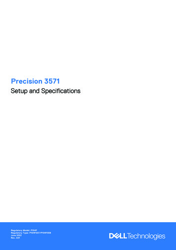
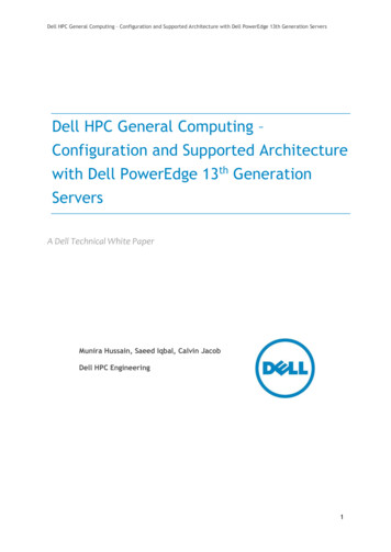
BatteryDell Precision T3500 Service ManualWARNING: Before working inside your computer, read the safety information that shipped with your computer. For additional safety bestpractices information, see the Regulatory Compliance Homepage at www.dell.com/regulatory compliance.Removing the Battery1.2.3.Follow the procedures in Before Working Inside Your Computer.Remove the computer cover.Lift the hard drive tray.NOTE: The memory module shroud has been removed to increase visibility to the following procedure.2.Use a small screw driver or a scribe to push the coin-cell release tab.3.Remove the coin-cell battery from the computer.
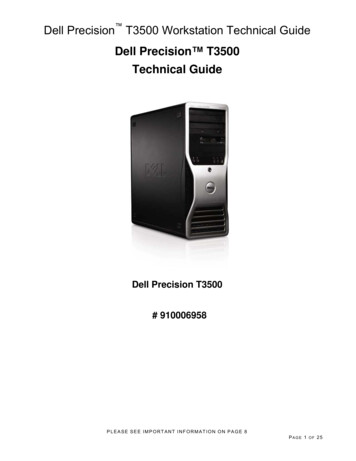
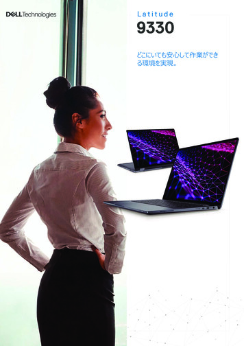
CoverDell Precision T3500 Service ManualWARNING: Before working inside your computer, read the safety information that shipped with your computer. For additional safety bestpractices information, see the Regulatory Compliance Homepage at www.dell.com/regulatory compliance.Removing the Cover1.Follow the procedures in Before Working Inside Your Computer.2.Pull the cover release latch toward the back of the computer.
3.Pivot the cover away from the computer and then remove the cover.
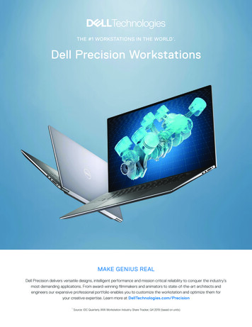
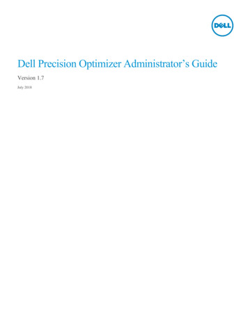
Drives BezelDell Precision T3500 Service ManualWARNING: Before working inside your computer, read the safety information that shipped with your computer. For additional safety bestpractices information, see the Regulatory Compliance Homepage at www.dell.com/regulatory compliance.Removing Drives Bezel1.2.3.Follow the procedures in Before Working Inside Your Computer.Remove the computer cover.Remove the front bezel.4.Push the sliding plate lever down to release the drives bezel.
5.Tilt the drives bezel away from the front of the computer.6.Remove the drives bezel from the computer.
Front BezelDell Precision T3500 Service ManualWARNING: Before working inside your computer, read the safety information that shipped with your computer. For additional safety bestpractices information, see the Regulatory Compliance Homepage at www.dell.com/regulatory compliance.Removing the Front Bezel1.2.Follow the procedures in Before Working Inside Your Computer.Remove the computer cover.4.While pressing the release tab down (1) slide the bezel toward the top of the computer (2).
5.Remove the bezel from the front of the computer.
Front Fan AssemblyDell Precision T3500 Service ManualWARNING: Before working inside your computer, read the safety information that shipped with your computer. For additional safety bestpractices information, see the Regulatory Compliance Homepage at www.dell.com/regulatory compliance.Removing the Front Fan Assembly1.2.3.Follow the procedures in Before Working Inside Your Computer.Remove the computer cover.Lift the hard drive tray:a. Push and hold the blue release tab toward the bottom of the computer.b.Raise the hard drive tray on its hinges.
4.Remove the memory module shroud.5.Disconnect the two fan cables from the system board.
6.Remove the screw securing the front fan assembly to the computer.7.Lift the front fan assembly straight up and remove it from the computer.
Floppy DriveDell Precision T3500 Service ManualWARNING: Before working inside your computer, read the safety information that shipped with your computer. For additional safety bestpractices information, see the Regulatory Compliance Homepage at www.dell.com/regulatory compliance.Removing the Floppy Drive1.2.3.4.5.6.7.Follow the procedures in Before Working Inside Your Computer.Remove the computer cover.Remove the front bezel.Remove the drives bezel.Disconnect the power and data cables from the back of the floppy drive.Push the sliding-plate lever down to release the floppy drive.Remove the floppy drive from the computer.Replacing the Floppy Drive1.2.3.4.5.6.7.Follow the procedures in Before Working Inside Your Computer.Remove the computer cover.Remove the front bezel.Remove the drives bezel.Connect the power and data cables from the back of the floppy drive.Push the sliding-plate lever down to secure the floppy drive in the computer.Place the floppy drive in the computer.
Hard DrivesDell Precision T3500 Service ManualWARNING: Before working inside your computer, read the safety information that shipped with your computer. For additional safety bestpractices information, see the Regulatory Compliance Homepage at www.dell.com/regulatory compliance.Removing the Hard Drives1.2.Follow the procedures in Before Working Inside Your Computer.Remove the computer cover.3.Disconnect the power cable and data cable from the first hard drive.
4.Lift the two release tabs on the first hard drive.5.Squeeze the two release tabs toward each other and hold.
6.Tilt the hard drive towards away from the release tabs.7.Remove the first hard drive from the computer at an angle.8.Repeat the process with the second hard drive.
Hard Drive TrayDell Precision T3500 Service ManualWARNING: Before working inside your computer, read the safety information that shipped with your computer. For additional safety bestpractices information, see the Regulatory Compliance Homepage at www.dell.com/regulatory compliance.Removing the Hard Drive Tray1.2.3.4.Follow the procedures in Before Working Inside Your Computer.Remove the computer cover.Remove the hard drives from the hard drive tray.Open the plastic ties securing the hard drive cables.5.Lift the hard drive tray:a. Push the blue release tab toward the bottom of the computerb. Raise the hard drive tray upward on its hinges.6.Continue releasing the hard drive cables from the plastic ties on the bottom of the hard drive tray.
7.Remove the three screws securing the hard drive tray to the computer.8.Remove the hard drive tray from the computer.
Chassis Intrusion SwitchDell Precision T3500 Service ManualWARNING: Before working inside your computer, read the safety information that shipped with your computer. For additional safety bestpractices information, see the Regulatory Compliance Homepage at www.dell.com/regulatory compliance.Removing the Chassis Intrusion Switch1.2.3.4.5.6.Follow the procedures in Before Working Inside Your Computer.Remove the computer cover.Lift the expansion card retention assembly arm away from the chassis (see Step 3, Removing the Expansion Card).Disconnect the intrusion switch cable from the system board.Slide the intrusion switch toward the center of the computer.Remove the intrusion switch from the computer.Replacing the Chassis Intrusion Switch1.2.3.4.5.6.Follow the procedures in Before Working Inside Your Computer.Remove the computer cover.Lift the expansion card retention assembly arm away from the chassis (see Step 3, Removing the Expansion Card).Connect the intrusion switch cable to the system board.Slide the intrusion switch toward the center of the computer.Place the intrusion switch in the computer.
I/O Data CableDell Precision T3500 Service ManualWARNING: Before working inside your computer, read the safety information that shipped with your computer. For additional safety bestpractices information, see the Regulatory Compliance Homepage at www.dell.com/regulatory compliance.Removing the I/O Data Cable1.2.3.4.5.6.Follow the procedures in Before Working Inside Your Computer.Remove the computer cover.Raise the hard drive tray.Remove the memory module shroud.Remove the front fan assembly.Disconnect the I/O data cable from the I/O panel.Replacing the I/O Data Cable1.2.3.4.5.6.Follow the procedures in Before Working Inside Your Computer.Remove the computer cover.Raise the hard drive tray.Remove the memory module shroud.Remove the front fan assembly.Connect the I/O data cable to the I/O panel.
I/O PanelDell Precision T3500 Service ManualWARNING: Before working inside your computer, read the safety information that shipped with your computer. For additional safety bestpractices information, see the Regulatory Compliance Homepage at www.dell.com/regulatory compliance.Removing the I/O Panel1.2.3.4.5.Follow the procedures in Before Working Inside Your Computer.Remove the computer cover.Raise the hard drive tray.Remove the memory module shroud.Remove the front fan assembly.6.Disconnect the I/O data cable from the I/O panel.
7.Disconnect the USB cable from the I/O panel.8.Remove the screw that secures the I/O panel to the computer.
9.Remove the I/O panel from the computer.
MemoryDell Precision T3500 Service ManualSupported Memory ConfigurationsRemoving and Replacing Memory ModulesYour computer uses 1066 MHz or 1333Mhz DDR3 unbuffered SDRAM memory. DDR3 SDRAM, or double-data-rate three synchronous dynamic random accessmemory, is a random access memory technology. It is a part of the SDRAM family of technologies, which is one of many DRAM (dynamic random access memory)implementations, and is an evolutionary improvement over its predecessor, DDR2 SDRAM.Supported Memory ConfigurationsSize(GB)DIMMRanksDIMM1 DIMM21SR1 GB2SR1 GB1 GB3SR1 GB1 GB1 GB4SR1 GB1 GB1 GB1 GB4DR2 GB2 GB6SR1 GB1 GB1 GB1 GB1 GB1 GB6DR2 GB2 GB2 GB12DR2 GB2 GB2 GB2 GB2 GB2 GB12DR4 GB4 GB4 GB24DR4 GB4 GB4 GB4 GB4 GB4 GBDIMM3 DIMM4 DIMM5 DIMM6 1333MHz TriNOTE: DDR3 DIMMs have 240 pins, the same number as DDR2, and are the same size, but are electricallyincompatible and have a different key notch location.Removing and Replacing Memory ModulesWARN
6. Select Run the 32 Bit Dell Diagnostics from the numbered list. If multiple versions are listed, select the version appropriate for your computer. 7. When the Dell Diagnostics Main Menu appears, select the test you want to run. Dell Diagnostics Main Menu 1.