Transcription
Power System ProtectionPart – VIIDr.Prof.Mohammed Tawfeeq Al-ZuhairiDifferential Protection(Unit protection)321
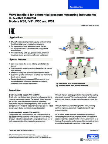
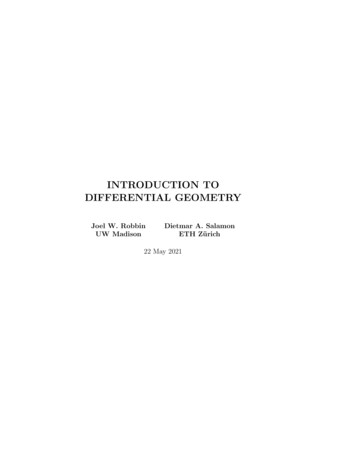
Power System ProtectionPart – VIIDr.Prof.Mohammed Tawfeeq Al-ZuhairiDifferential Protection Differential protection is the best technique in protection. In this type ofprotection the electrical quantities entering and leaving the protected zoneor area are compared by current transformers (C.T.s). If the net differenceequal zero, it means no fault exist. This system is operating in either of the two following principles:1. Current balance principle.2. Voltage balance principle. Differential protection is applicable to all parts of the power system:1. Generator.2. Transformers.3. Motors.4. Buses.5. Lines and feeders.6. Reactors and capacitorsThere are two basic types of differential protection: Current Balance Differential protection Voltage Balanced Differential Protection1. Current Balance Differential protection: Operation during internal and external fault conditionsFig.1 shows the basic current differential protection based on currentbalance principle.- At normal conditions and for external fault at F, CT1 and CT2circulate currents at their secondary’s Is1 and Is2 (Is1 Is2) and nocurrent flow through the relay (ΔI Is1 - Is2 0), hence the relay willnot operate.- If fault occurs at point F within the protected zone (internal fault) asshown in Fig.2, and the fault is fed from both sides, then currentthrough C.T2 will be reversed. Therefore a current ΔI Is1 Is2 willflow in the operating winding of the relay. This will cause the relay totrip the circuit breaker connected to the faulty system. Hence the relaytrips when Is1 Is2 I I pick up current of relayThis form of protection is known as Merz-Price protection.321
Power System ProtectionPart – VIIDr.Prof.Mohammed Tawfeeq Al-ZuhairiFig 1Consider ideal current transformer performance Ip1 Ip2 Therefore Is1 Is2 Therefore ΔI 0, magnitude of I 0 Current measuring relay does not operate.325
Power System ProtectionPart – VIIDr.Prof.Mohammed Tawfeeq Al-ZuhairiFig. 2 internal fault with two infeed.Consider ideal current transformer performance If Ip1 Ip2 Therefore Is1 Is2 Therefore ΔI Is1 Is2 0, magnitude of I 0 Current measuring relay operates.321
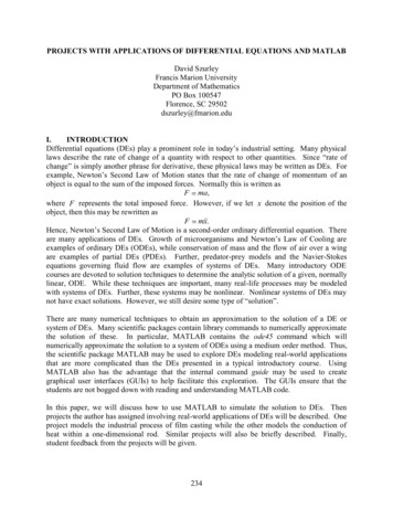
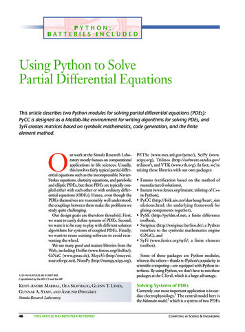
Power System ProtectionPart – VIIDr.Prof.Mohammed Tawfeeq Al-Zuhairi-Relay may also operate if the fault in feed is from one direction as shown infig.3.Fig 3 internal fault with one infeed.Consider ideal current transformer performance: If Ip1 as Ip2 0 i.e no fault current in feed from one side. Is2 0 Therefore ΔI Is1 0, magnitude of I 0 Current measuring relay operates.2. Voltage Balanced Differential ProtectionInstead of current balance, a voltage balance Mertz-Price system, shownin Fig.4, is used for feeder protection or equipment protection (unitprotection). CT1 & CT2 secondary windings are connected in opposition so that thereis no current flow in the relay operating coil (V s1 Vs2 relay notoperate).- During internal fault Vs1 - Vs2 0, this will drive current through theoperating coil of the relay and the relay will operate.Fig.5.321
Power System ProtectionPart – VIIDr.Prof.Mohammed Tawfeeq Al-ZuhairiFig 4Consider ideal current transformer performance: Ip1 Ip2. Vs1 Vs2 and Is1 Is2 0. Therefore magnitude of I 0 Current measuring relay does not operate.Fig 5.321
Power System ProtectionPart – VIIDr.Prof.Mohammed Tawfeeq Al-ZuhairiConsider ideal current transformer performance: Vs1 Vs2. Therefore magnitude of I 0 Current measuring relay operates. The characteristics of differential protection can be summarized asfollows:Simple Concept: Measure current entering and exiting the zone of protection If currents are not equal, a fault is presentProvides: High sensitivity High selectivityResult: Relatively high speed Percentage Differential Current RelayThis relay has an operating winding and two restraining winding connected asshown in Fig.6. The function of the restraining windings is to preventundesired relay operation should a current flow in the operating winding due toCT during external fault.Figure 6—Basic relay connections (one phase) for fixed percentage restraintdifferential relay.321
Power System ProtectionPart – VIIDr.Prof.Mohammed Tawfeeq Al-ZuhairiAt Normal conditions: The differential current in the operating coil is proportional to Is1-Is2.Iop Is1-Is2 The equivalent current in the restrain windings are proportional to½ ( Is1 Is2) since the two restrain windings are identical.Irest ½ ( Is1 Is2) Therefore, the ratio of the differential operational current to the averagerestrain current is a fixed “percentage”. In other word, we can define thebias as the ratio between the numbers of turns of the restrain coil to thenumber of turns of the operating coil, i.e. k is typically (10 – 40%). The operating characteristics of the relay is shown in Fig.7Fig. 7 Typical operating characteristic of a percentage differential relay.The electromagnetic forces are proportional to the square of the magnetomotive force (mmf).The condition for relay operation is then:(mmfop )2 (mmfr )2(Is1-Is2) No ½ ( Is1 Is2) Nr(Is1-Is2) No ½ (Is1 Is2) k No311
Power System ProtectionPart – VIIDr.Prof.Mohammed Tawfeeq Al-ZuhairiIs1 (½ ( Is1 Is2)) k Is2Is1 – ( k /2) Is1 ( ½ Is2) k Is2Is1 (1 –½ k) Is2 (1 ½ k)These characteristics can be achieved using balanced beam relay shown inFig.8.Fig.8 Balanced beam relay with restrain. (a) Balanced beam type relay (b)Schematic313
Power System ProtectionPart – VIIDr.Prof.Mohammed Tawfeeq Al-Zuhairi312
Consider ideal current transformer performance: I f I p1 as I p2 0 i.e no fault current in feed from one side. I s2 0 Therefore ΔI I s1 0, magnitude of I 0 Current measuring relay operates. 2. Voltage Balanced Differential Protection Instead of current