Transcription
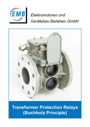
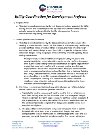
Transformer Overcurrent Protection CoordinationRussell W. PattersonElmo PricePatterson Power EngineersConsultant, ABB Inc. RetiredIntroductionIEEE Guide for Liquid-Immersed Transformer Through-fault-current Duration C57.109-1993(R2008) defines the transformer damage curve that is used for transformer overcurrent protection.This method is further discussed and provided with examples in Appendix A of IEEE Guide forProtecting Power Transformers C37.91–2008. This paper presents a tutorial with informationdrawn from these two guides highlighting the damage curve development and its use for differenttransformer MVA capacities. Also discussed are the effect of different winding configurations oncoordination.Transformer Damage CurveIEEE Guide C57.109-1993 (R2008) considers both thermal and mechanical effects for externaltransformer through faults. The transformer’s capability to withstand these effects is shown inFigure 1. The thermal capability is a long used curve developed empirically and originally publishedas a table in ANSI C57.92-1962, American National Standard Guide for Loading Oil-ImmersedDistribution and Power Transformers and republished in C57.109-1993 (R2003). This data is shownin Table 2 for Times Rated Current values up to 25. It was originally developed and used fortransformer protection without consideration for the accumulated effect of mechanical stressesduring short circuits. Over the past 50 years or more the mechanical effect of short-circuits have beenmore accurately defined based on application. Today, the capability curve is modified in the shorttime, high current region showing the transformer’s mechanical limit more accurately consideringthe accumulated effect of through-faults. This modification is shown in Figure 1 and identified byMechanical Capability. This curve, however, is not uniform for all transformer sizes. In some casesthe Thermal Capability alone is sufficient to address thermal and mechanical requirements and inother cases a Mechanical Capability limitation must be implemented. Therefore, transformerapplications are divided into four categories based on their kVA and through-fault exposure. Thesecategories are shown in Table 1. The capability curves for each category are shown in Appendix Aand are discussed below.Understanding I2tI2t (I amps, t time) A2s is proportional to the increase of thermal energy (heat – Ws) in a conductorwith a constant current over time. In transformers an I2t value is defined to show the thermal limitsof their windings before damage occurs. The values I (times rated winding current) and t fromC57.109 are reproduced in Table 2 with an additional column showing the calculated I2t value. Also,two additional rows for I equal to 35 and 40 are added. The data is based on symmetrical fault currentin the winding. As can be observed each point for I between 2 and 25 has a different I2t valueproducing the “Thermal Capability” curve of Figure 1.1
It should be noted that this curve represents the thermal limit for short circuits. It is a defined curveand does not include the effect of the transformer’s operating environment. Thermal limits foroverloads, however, are addressed by transformer oil and/or winding temperature measurementthat need to be considered where the current is less than 3.5 times the transformer’s winding ratedcurrent. Refer to the IEEE Guide for Loading Mineral-Oil-Immersed Transformers and Step-VoltageRegulators C57.91-2011 for more information.20001000500300Time (Seconds)200(2, 1800)This curve provides shortcircuit thermal capability.Operation in this region( 3.5 times base I) mayhowever result fromoverloading. Refer to IEEE Std(3, 300)C57.91 -2011.ThermalCapability1003.5(4.75, 60)5030(6.3, 30)20MechanicalCapability10(11.3, 10)(frequent faults)532(25, 2)1123 4 57 1020 30 40Times Nominal Base CurrentFigure 1. Example Transformer Damage Curve2
Table 1. Transformer CategoriesCategoryThree phaseSingle phase(Minimum nameplate KVA)(Minimum nameplateKVA)I5 - 50015 - 500II501 - 1667501 - 5000III1668 – 10,0005001 – 30,000IVAbove 10,000Above 30,000Table 2. Short time thermalload (and short circuit) capabilityTimes ratedcurrent (I)Time inseconds 101277252125035*1.02125040*0.781250*Extended curve for Category I transformersRated Winding CurrentThe referenced transformer standards use the terms rated current and nominal base current withoutclear definition. As protection engineers we consider the rated or base current as the transformer’rated line current. This permits computation of current on all sides of a transformer for a throughfault (e.g. from HV to LV) in per unit. The terms rated and base current in this paper and referencedstandards, however, refer to the winding current, which is different than the line current in the caseof delta connected windings. This difference has an impact that affects proper coordination with thedamage curve and will be discussed in a later section. To reiterate, in this paper the terms ratedcurrent and nominal base current refer to the rated winding current, which is the current in thewinding when the transformer is operating at rated KVA and rated voltage.3
Determining the Damage CurveThe transformer’s through fault withstand capability curve can generally be provided by themanufacturer if requested by specification. If not available it can be defined completely or in part,depending on the category, by the thermal capability characteristic of Figure 1. The mechanicalcapability characteristic is introduced to account for the loss of the winding’s mechanical integritythat occurs with the exposure to frequent through-faults, their duration and magnitude. Table 3 atthe end of this section provides a guide for selecting the appropriate damage curve.Fault FrequencyAn attempt is made to define the transformer’s fault exposure as frequent or infrequent. Frequent fault exposure is where there are a defined number of through-faults in thetransformer’s lifetime above a defined current magnitude, which is expressed as percent ofthe transformer’s maximum through-fault current (IMax). Infrequent fault exposure is where there are fewer transformer through-faults in thetransformer’s lifetime than the defined number and magnitude given above for the sametransformer category.The defined number of faults and their magnitudes for fault frequency are defined differently forCategories II, III and IV and summarized in Table 3.ApplicationThe protection normally provided that coordinates with the damage curve is typically an inversetime-overcurrent device such as a fuse or relay. It may be the primary (the only) protection used toclear the through-fault, or it may be the backup protection to another primary device or system thatdetects and clears the fault high-speed. High-speed fault clearing is normally 100 - 200 ms., which istypically less than one tenth of the clearing time when using a time-overcurrent device for protectionof the thermal curve of Figure 1. Therefore, the accumulated mechanical stress on the winding isproportionally less and the mechanical characteristic may not be required. One has to also considerthe potential failure of the protection system to clear all faults high-speed. Such occurrences mustbe infrequent. Therefore, the capability curve used for protection coordination also depends on theprotection being applied – primary (the only protection) or backup to high-speed.Maximum Through-fault Current, IMaxThe maximum transformer symmetrical through fault current (IMax) used to define the mechanicalcapability and is limited by the positive sequence transformer or the sum of the positive sequencetransformer and source impedances. It is the winding’s maximum current withstand capability at 2seconds. Although not specifically stated in the referenced standards the calculation of IMax is basedon a simple three-phase through-fault calculation where the impedance values are in per unit of thetransformer base impedance. Per unit voltage is assumed to be 1. Only the transformer impedance,ZT, is used to compute IMax for Category II transformers and the transformer, ZT, plus source, ZS,impedance is used for Category III and IV transformers.Category IIIMax 1/ZT(1)Category III and IVIMax 1/(ZT ZS)(2)Category III and IV transformers are larger MVA transformers with higher through-fault currentsthat produce considerably more forces acting upon the windings and thus require using theequivalent source impedance at the transformers location as part of the transformer design criteria.The source impedance should be specified to the transformer manufacturer. If not the manufacturerwill use the appropriate information from Table 4 to compute a source impedance. Table 4 is copied4
from IEEE Guide C57.109-1993 (R2008) except the % impedance at 100 MVA is derived to showrelative values of source impedance.Table 3. Capability curve application requirementsCategoryFault FrequencyApplicationCapability CurveIN/AFrequent 10 faults 70% IMaxin LifetimeInfrequent 10 faults, etc.Frequent 5 faults 50% IMaxin LifetimeInfrequent 5 faults, etc.N/ABackupThermalThermal pThermal andMechanicalThermalEitherThermalPrimaryThermal andMechanicalN/A – Not Applicable, ZT – Positive sequence transformer impedance,ZS – Positive sequence source impedance used by manufacturer for designIVFrequent or InfrequentEitherIMax pu @2 secondsN/A1/ZTN/AN/A1/(ZT ZS)N/AN/A1/(ZT ZS)Table 4. System short circuit apparent power tocompute source impedanceMaximum SystemVoltage (kV)Below tem Fault CapacitykA 50200845020080693008097000% Impedance at100 Category I TransformersCategory I transformers are limited to 500 kVA (or kVA parts in the case of autotransformers) andare generally applied on distribution systems. They require appropriate primary fusing for clearinginternal faults where the transformer has failed, and severe secondary faults, which are consideredinfrequent. Most secondary faults, however, are cleared by other secondary protection devices such5
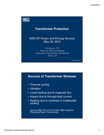
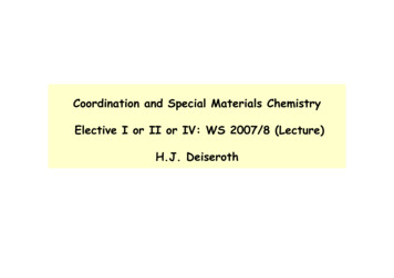
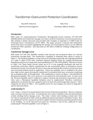
as fuses and molded case breakers and do not impose severe mechanical stress on the transformer.Therefore, the additional mechanical limitations of the curve are not required.The Category I curve is also extended with a constant 1250 A2s thermal capability (the valuecalculated in Table 2 for 25 times rated I for 2 seconds) to include transformers with impedancesdown to 2.5%. This impedance will permit a through-fault current up to 40 times rated current.Refer to the Category I curve of Appendix A.Category II TransformersCategory II transformers are equal to or smaller than 1667 kVA single phase and 5000 kVA threephase and are applied in accordance with Equation 1 and Table 3 depending on the application andprotection. Primary (high voltage) protection is normally time coordinated with secondary devicesthat are not high-speed. Therefore, more often than not the use of the mechanical characteristic isrequired. Consider the following example.The 5000 kVA transformer is protected by a time overcurrent device that must trip before damageoccurs to the transformer and coordinate with secondary devices. In this example we are primarilyinterested in defining the appropriate transformer damage curve. The maximum through-faultcurrent is calculated in accordance with Equation 1 using only the transformer impedance and isfound to be (1/0.076) 13.2 pu. It is determined that there will most likely be greater than 10 faultson the transformer secondary in regions 1, 2 and 3 that are greater than 70% of 13.2 pu – 9.24 pu.Therefore the mechanical characteristic is desired. From this we can define the two end points of themechanical characteristic. The point at IMax is by definition 13.2 pu A at 2 seconds. From these valuesI2t (13.22·2) is calculated to be 348.5 A2s. The limiting withstand time at 70% IMax (9.24 pu) iscalculated with this constant I2t value as 4.08 seconds (t 348.5/9.242). The mechanicalcharacteristic implementation is shown in Figure 3.12RP35000 kVA35 to 12.47/7.2 GrdY kVXT 7.6%RECLRSInfrequent fault zoneFrequent fault zoneFigure 2. Category II Application6
Time (Seconds)100503070% IMax20IMax109.24, 4.084I2t 348.513.2, 22ZT 7.6%12 3 4 5 7 10Times Nominal Base Current, IR20 30Figure 3. Category II Mechanical Characteristic ImplementationCategory III TransformersCategory III transformers are equal to or smaller than 10 MVA single phase and 30 MVA three phaseand are applied in accordance with Equation 2 and Table 3 depending on the application andprotection. Primary (high voltage) protection is coordinated with secondary devices that may or maynot be high-speed. Therefore, it is important for the protection engineer to understand theapplication. Consider the example of Figure 4.87T213RP15/20/25 MVA115 kV - 13.2 GrdY/7.62 kVXT 8.5%RSRS 50 Blocking of RPInfrequent fault zone Frequent fault zoneFigure 4. Category III Application7
The 15 MVA transformer is protected by a time overcurrent device that must trip for through-faultsbefore damage occurs to the transformer and coordinate with secondary devices. In this example weare primarily interested in defining the appropriate transformer damage curve. The maximumthrough-fault current is calculated in accordance with Equation 2 using the transformer and sourceimpedance. The source impedance was not specified to the manufacturer at the design time,therefore the source impedance derived from Table 4 is used. From Table 4 we use the system faultcapacity MVA where the maximum system voltage is 121 kV. In this case the system per unitimpedance expressed on the transformer’s MVA base is very small and could easily be neglected.This is probably true for most Category III applications.ZS MVAT/MVAS (on Transformer
Refer to IEEE Std C57. 91¡ -2011. (2, 1800) (3, 300) (4. 75, 60) (6. 3, 30) (11. 3, 10) (25, 2) Thermal Capability M echanical Capability (frequent faults) Figure 1. Example Transformer Damage Curve . 3 Table 1. Transformer Categories Category Single phase (Minimum nameplate KVA) Three phase (Minimum nameplate KVA) I 5 - 500 15 - 500 II 501 - 1667 501 - 5000 III 1668 – 10,000 5001 .File Size: 1MBPage Count: 23