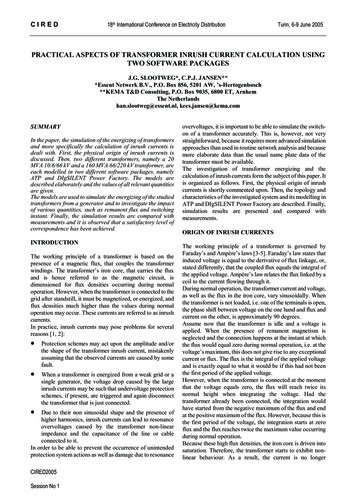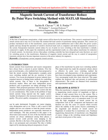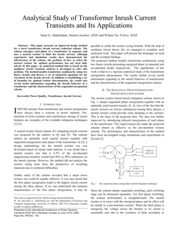
Transcription
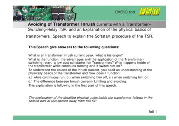
EMEKO andAvoiding of Transformer Inrush currents with a Transformer–Switching-Relay TSR, and an Explanation of the physical basics oftransformers. Speech to explain the Softstart procedure of the TSR.This Speech give answers to the following questions:What is an transformer inrush current peak, what is his origin?What is the function, the advantages and the application of the Transformerswitching-relay, a low cost softstarter for Transformers? What happens inside ofthe transformer while continuos running and if switch him on?To understand the causes of the inrush current, you need an understanding of thephysically basics of the transformer and how does it function:a.) while continuous run, b.) when switching him off, c.) when switching him on.d.) The difference between Inrush current- Limiting and avoiding.This explanation is following in the first part of this speech.The explanation of the detailled physical rules inside the transformer follows in thesecond part of this speech away from foil 54:foil 1
EMEKO andTransformers always are producing inrush current peaks!Nearly everybodyknows that!Just when switching ona transformer,sometimes the fusetrips and sometimeshe stay ok. Why?(The fuse in the picturehas a value of 0,8Aand was double ofthe nominal current,of the transformer,but although, he tripsafter any time,because of theovercurrent stress.)More than double of the nominal current is not enough!!foil 2
EMEKO andParticularly toroidal core transformers must have oversized fuses.An 1kVA Transfo must have an 20A PKZM-T line breaker, and thereforea value of 5 times of the primary nominal current.Without avoiding of the insrush current that leads to foolish fuse values.An 1600VA or bigger toroidal Transformer size is not fusiblewith elements listed in top.foil 3
EMEKO andWhat happens in the transformer ironcore-1:While continuousoperation:The primary voltage cycles arechanging the dense ofmagnetisation B, in apermanently manner.The positive Voltagehalfcycle transports theamplitude of themagnetisation B, from thenegative to the positivereturn point of thehysteresic loop, reachingit at the end of the pos.halfcycle.The negative Voltagehalfcycle, brings back theB to the negativereturning point of thehysteresic loop.And so on and on. Only the voltage-time-area of an Voltage half wave isresponsible for this transportation of the B. (The noload-primary current is only the answer from the transfo.)With the voltage-time-area of a fullwave, see on top, theamplitude of the magnetisation B, walk round the hysteresicloop one time.Foil 4
EMEKO andWhat happens in the transformer iron core-2 : When switchingoff to the end ofan half wave:The last positiveVoltage half wavetransports themagnetisation B, tothe positive returnpoint of theHysteresic-loop.The small negativevoltage time areatransports the B tothe pos. max.residual induction,the max.remnance.Following the Bstands still and fixin the pos. max.remnance point.The sight with the voltage time areas helps to easyer understanding what happens.Why goes the voltage to negative: Because of the inductivecurrent value, which holds conducting the thyristor until thiscurrent is near zero, originate the neg. voltage time areaand to spell it like the answer of the transformer whenfoil 5switching off.
EMEKO andCauses of the inrush current, a simple explanation-1:neg. Saturation to the End of the neg. Voltage Half Wave. Prehistory: Switch off was to the end of an negative Voltage half Wave. (Opposite tothe state in the example on foil 5!) Remnance was set therfore on the negative max.remnance point and stays there for longtime. See also the remnance test on the end of thisspeech on foil 59.Switch on happens now to the begin of the negative voltage halfwave, (In the graphic upleft in the top curve.) Now the magnetisiation is brough from the negative remnance pointto the negative saturation, reaching his max. to the end of the negative voltage half wave.That is the worst case switch on, following with the highest Inrush current peak.foil 6
EMEKO andCause of the Inrush current peak, a simple expanation-2. The iron core goes into saturation, when a new voltage half wave does not changethe direction of magnetisation in the iron core, and he is furthemore driven in thesame direction for magnetisation as before. And if this happens from an highmagnetisated Point, with a high B, then the iron goes into saturation.(Up to a B from 2 Tesla begins the saturation.)The remnance is the magnetically memory of the Iron core. He stays longtime therefixed at one point. See on foil 59. The high of remnance is depending of the air gap inthe transformer iron core. No air gap brings high remnance. A large air gap of any 0,1mm for an 1kVA Transfo brings a remnance near zero.If Switch on a transformer with an half wave in an direction opposite to his switch offhalf wave, then the inrush is low because the saturation is low, because the core isbeeing changed in magnetisiation direction. (But because nowbody knows theamplitude and direction of the remnance, you cannot measure it from outside tof thecore, you cannot start directly the transformer in the best case without inrush currentpeaks. You can only doing that per accident perhaps 1 time inside 10 switch on trials.It s a bit like russian roulette.)While core saturation, only the copper resistance of the primary coil is limiting thecurrent amplitude. It s than a transformer without iron core in this saturation sate for ashort moment.foil 7
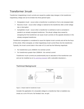
EMEKO andThe cause of the Inrush current-3. For that circumstance the current rises to very high amplitudes!In the case of iron core saturation, only the primary coil copperresistance added to the Grid line impedance is limiting the currentfor this half wave of the voltage. In this case the inductiveresistance of the transformer is lost.The inrush current can rise up to the amplitude of 100 times of thenominal current, at toroidal transformers, in the first half-wave.The more the losses of an transformer goes to a minimum, themore higher rises the inrush current.(The line impedance is about 0,3 Ohm at a grid for 230V with 1632 Amps, the transformer primary coil resistance is about. 0,3 Ohmat an 1,6 kVA Transfo, the plug cable resitance of 0,4 Ohm.)That limits the inrush current up to amplitudes of about 310Apeak inthe first half wave after switch on.foil 8
EMEKO andStandard methodes to limit the inrush current, the „EinSchaltstrom-Begrenzer“, ESB.Start with an additionally resistor in the input.ÎESB with a fix valueResistor and with a bridgeover it after a short time.Rel.ZuTrafoNetz3,5 Ohm 10 WÎ ESB with an NTC resistor,with or without a delayedbridge.Foil 9
EMEKO andWhen a standard ESB starts onto a short circuit after the transformer! Curve on top, Voltage onTransfo clamps. Curvebottom, current into transfo.Before bridging the resistor,the Losspower at the only10W resistance is 12kW.After bridging him, thecurrent rises up to 300Apeak.At the next start, the ESBcannot work properly,because the bridge relay isdamaged from theOvertemperature of theresistor of the 12KWoverload, and cannot bridgehim the next time.This was truly tested fromEMEKO.Foil 10
EMEKO andNTC- resistors are frequently used for inrush current limiting.This NTC Resistors arepermanently hot whentransformer is in the Switch onstate.That s a cheap but not a goodsolution. But the most amount oftransformers ar softstarted likethis, with NTC with a highresistance before start and a lowresistance after they are hot.The picture shows damaged NTCresistors, because of restart aftera short time after switch off, andthe NTC has been hot and lowresistive, and following highcurrents have destroied them.Foil 11
EMEKO andDisadvantages from (ESB s), inrush current limiters.Problems occur if an ESB s is switching on if the transformer has an overloador a short circuit at his output. The current limiting resistor gets anovertemperature. He can bee destroied or destrois other electronicelements inside the ESB.Therefore all Inrush current limiters are not shortcircuit proof.They could only be restarted if his temperature is down, that needs mostly a minimumof 1 minute waiting time between stop and next start.If an overload state occurs while starting, the current rises to a second and high inrushcurrent peak, because of the bridging of the resistor at an unsynchrounosly timeto the grid. Fuse trips than in this case.All inrush current limiters cannot handle with the the so called voltage dips.(Because the bridging relays is to slow to open while the dip duration of only anhalf wave or the NTC resistor cannot cool down fast enough in this case, if thevoltage retourns after the short dip.) For electro medical equipments the voltagedip thest is a must. The effect of the voltage dips on to a transformer is declairedlater in this speech, away from foil 33. And therefore much of our customers areproducers of electro medical equipments.Foil 12
EMEKO andResume of the disadvantages of ESB s.There are also other limits for ESB s. Those are: Frequently switching, start and stop and start again. Switching on with overload. Switching on onto a short circuit. Short time interrupts of the grid voltage. (Voltage Dips.) If a transformer must be fuses with his nominal currentvalue on the primary side, current limiting is not enough. Life cycles of maximum 20.000 cycles. Switch off an on with an voltage hysteresis, againstmalfunctions from the contactors in a machine controlsystem.Foil 13
EMEKO andIf a peak voltage switching solid state relay starts an Toroidaltransformer.As an deterrend example.Although any producersof solid state relays aretelling, tor start antransformer the switchon with an peakvoltageswitcher ist the bestwhot you can do.But the result is to seenin the graphic at right, ifswitch on to an toroidaltransfo.Also in the scientificliterature ist often bewritten, that the peakswitching is the best forall kind of transformers.Only for a transformerswith a big air gap is thepeak switchingprocedure a convenientsolution.Foil 14
EMEKO andA TSR is not an inrush current limiter, he avoids the inrush.A TSR avoids inrush current peaks because ofit s premagnetising procedure and his fullswitch on cycle to the physically correct moment. To understand all this precisely, you must firstread the physically basics for the transformeraway from foil 55. Following is showed, how the TSR does it sswitching, and where the TSR is used and whichadvantages then you can have with it.Foil 15
EMEKO andTSRL Starting procedure with only the flowing of the off-load current at an1kVA EI-weldedcore transfo if he is in off-load state. Red curve: Voltage at transfo. Blue curve: Current into transfo. Scalefactor is 0,5 A / div. ( Directly after fullon switching, just the off-load current is flowing, knowing on his typically shape.) Can anybody make a better transformer start?Foil 16
EMEKO andTSRL Start procedure of an 5kVA EI-core transfo with his nominal load. Red curve, voltage on the transformer clamps. Blue curve: current intotransformer. Scale factor is 20A per div.No inductive current peaks are seen only the resistive current from the load.No difference in Switch on behaviour between noload and load at the sameadjusting of the high and width of the voltage areas to premagnetise thetransformer correct, here 3,2 msec. width.Foil 17
EMEKO andOne from „about 1000“ different Applications of the TSRL. For a machine to exportfrom one customer, theAdapting transformer for115V to 230V stays foreverytime in the Machine,also if the tranformer is notneed.With a „Bridge 1“ over 2clamps, in conjunction withthe different connectors for115V or 230V, the Functionof transformer is selected ornot.The TSR allows the fusing ofthe nominal vlue of theprimary current and avoidthe trip of the Building fuseat the machine customer.Foil 18
EMEKO andThe Transformer-Switching-Relay, Function und drawing scheme.The TSRL, as an bridged solid state relay,correspond EN60947-4-3, is switching in a softmanner, without a Pre-Resistor, and thereforeload un-depending. The premagnetissing cycletransports with small unipolar voltage timeareas the Magnetisation B, to the right point toswitch on in a physically correct manner.Foil 19
EMEKO andThe TSRL is short ciurcuit proof under normally* circumstances.-1. The graphic at right shows a switchon cycle from TSRL onto a shortcircuit 2kVA toroidal transformer (Thetransformer output has a shortcircuit.)Upper curve from the line voltage,after the fuse, shows his tripping.Lower curve shows the flowingcurrent into the transformer.The fuse, an R10A LS Line protectorswitch is tripping after the 6.premagn. Voltage time area.The Thyristor can conduct 500A for10 msec. and gets here, at the only80A high and only 2 msec. widthpeaks naturally no damaging.If a higher valued fuse not trip whilethe premagnetisiation, the he tripsshurely at switching on, seen in thenext foil 21.* Normally circumstances are a 230Vor 400V grid with max. 32A fuses withcorresponding cable area sizes.Foil 20
EMEKO undThe TSRL is short ciurcuit proof under normally* circumstances -2. Mit B 16A LSS fusedWhile premagnetising the B- 10A LSSline protector switch does not trip.When switching full on the mechanicalrelay bridges the Thyristor.TheThyristor can lead 500 A for 10msec., but he must lead here only 80Afor 2msec., also no problem for him.The mechanical Relais can lead 500Afor 10msec., but he must lead hereonly 240A for 10msec.Notice:An B 10A Lineprotectorswitch is notselective to an C 16ALineprotectorswitch.But a B10 Lineprotectorswitch isselectiv to a preconncted 25A- gLfuse, if the max. current is 1kA.(That means if Ik 1kA only theB10A Lineprotectorswitch is trippingand not the 25AgL fuse.)That shows significant, that an 25AgLfuse is enough for a 6kVA bis 10 KVAmedically IT-Transfo in future togetherwith an T
resistance of the transformer is lost. The inrush current can rise up to the amplitude of 100 times of the nominal current, at toroidal transformers, in the first half-wave. The more the losses of an transformer goes to a minimum, the more higher rises the inrush current. (The line impedance is about 0,3 Ohm at a grid for 230V with 16-
