Transcription
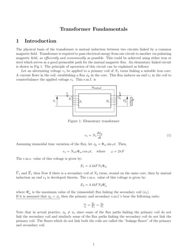
Power Transformer Fundamentals:Design and ManufacturingWaldemar Ziomek, Engineering ManagerCG Power Systems Canada IncIEEE Training, Houston, Texas,Oct.8-9, 20131Overview Transformer Design– Transformer Types– Construction and Parts Core & Coils– Electrical design Losses & Impedance Thermal, Dielectric & Short Circuit Cooling & Sound Level– Mechanical design Tank Oil Preservation Transformer Manufacturing Process2
Power Transmission & DistributionThe traditional power supply chain - from thecentral power generator to the consumer:GENERATIONTRANSMISSION115/10 or 20 kV132161230345500Generator 0/115230/132DISTRIBUTIONDISTRIBUTED nTransformerWith and without LTCPads3Specification vs. Design SPECIFICATION GIVES BASICPARAMETERS:– Voltages (kV, BIL) ,– power rating ( MVA),– impedance (IZ), DESIGNER/PRODUCER GIVES:– Dielectric system– Magnetic system– Thermal system– Mechanical system– Oil flow ‘system’– Sound ‘system’4
Standards USA (ANSI) IEEE Std C57.12.00-1993, standard general requirements for liquidimmersed distribution, power and regulation transformers 50 Pages ANSI C57.12.10-1988, safety requirements 230 kV and below 833/958 through8,333/10,417 KVA, single-phase, and 750/862 through 60,000/80,000/100,000KVA, three-phase without load tap changing; and 3,750/4,687 through60,000/80,000/100,000 KVA with load tap changing 30 Pages (ANSI) IEEE C57.12.90-1993, standard test code for liquid-immerseddistribution, power and regulating transformers and guide for short-circuittesting of distribution and power transformers 107 Pages NEMA standards publication no. TR1-1993; transformers, regulators andreactors 2 Pages CSA IEC5Simple Transformer Left coil - input(primary coil)– AC Source is connectedto– Magnetizing current flowsand establishes the fluxin core Right coil - output (secondarycoil)– Load Magnetic circuit (core) Problems ? Stray flux, transients,heating, vibrations, noise, losses,regulation, saturation, human errors,dielectrics (high voltage insulation),non-linear magnetics, fluiddynamics, material defects,contamination, etc.etc.6
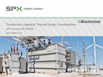
Real single phase transformerWound legLV windingHV windingReturn core legIn order to better control the stray flux distribution, both windingsare wound on same core leg7Equivalent CircuitRp jXpRs jXsLoadRmXmRp Rs ’XmRmXp Xs’Load8
Transformer Design BasisThermalDielectricShort Circuit Quality Reliability Consistent performance Long Service life9Design Procedure Select Core Diameter & Area (A) Select Maximum Flux Density (Bm) Find Volts/Turn 4.44 x Freq x Bm x A Find LV Turns LV volts per Phase/ (V/T) Find HV Turns HV volts per Phase/ (V/T) Select current densities LV & HV Select Conductor Area Current / Density Select type of Winding:– Helical,Disc,Center-fed,end-fed Finalize HV Axial & Radial Finalize LV Axial & Radial10
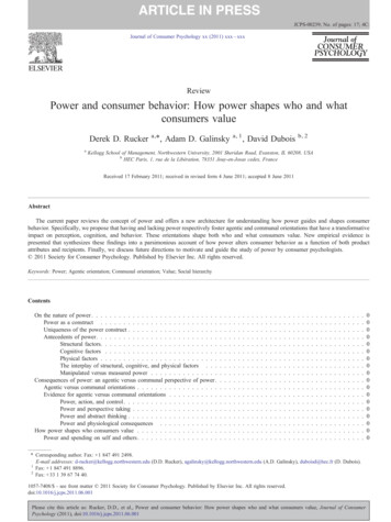
Design ProcedureSelect Core - LV; LV-HV DuctsDraw Ampere - Turn diagram I T 2 k lavg a1 a2 10 4Find Impedance % :ux xk 7.9 f N R h 3SNkR 1 3 %a1 a2 hα1, α2, δ - radial dimensions of two windings and the gaplavg π D1-2where D1-2 OD1 δCheck with guaranteed impedance, adjust V/T, height to getrequired impedanceFinalize frame size- CD x WH x LCFind Iron LossFind Load LossCheck for short circuit withstandCheck for thermal withstandCheck for impulse withstand 11Design OptimizationTransformer parametersas a function of core diamaterHeight [m]200101809Cu [ton]Fe[ton]1608Active part [ton]Height [m]Mass [x 1000 kg]14071206Active 0110012001300Core diamater [mm]12
Design Optimization Winding which are closer to each other havelower impedance. The taller the winding – the lower theimpedance. Impedance is changing in power two with thenumber of turns. Transformer impedance expressed in Ohms isindependent from MVA base13Construction Type and Main Parts Core- or Shell Form Windings – Circular for core-type , Pancakefor shell-type Solid Insulation (turn-to-turn, section-tosection, winding-to winding, coil-tocore/clamp) Insulating liquid (coolant and main insulation) Tank Cooling equipment (radiators, coolers)14
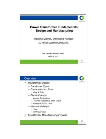
Shell Form1. high voltage bushing2. tank top section3. cooling equipment4. oil circulating pump5. tank bottom section17. pancake coil18. inter-phase block19. L.V. coil group20. H.V. coil group24. tank shielding25. insulating washer15Core Form Concentric windings‘Set’ Winding GeometryCooling optionsCost considerationShipping differences16
Core Form17Types of Cores–3 legs Type 1 –––Type 2legs and yokes not of equalcross sectionsingle-phase2 legs 2 wound legs–legs and yokes of equal crosssectionsingle-phase–3 legs–legs and yokes of equal crosssection18three-phase– Type 31 wound leg2 return legs–3 wound legs
Types of Cores cont.–4 legs Type 4 –legs and yokes not ofequal cross sectionsingle-phase–5 legs– –Type 52 wound legs2 return legs–3 wound legs2 return legslegs and yokes not ofequal cross sectionthree-phase19Core Cutting “Core Form Design” Fully mitered & step lapped in corner joints improves flux distribution, minimizes losses & sound level Circular core shape provides windings with optimum radial support20
Core Stacking MethodsBUTT-LAP STACKING: Local concentration of flux higher excitation current & core lossSTEP-LAP STACKING: Reduced Local flux concentration lower excitation current & core lossCore Material- Grain Oriented SiliconM - NON-LS; H - LS HZDKH (laser scribed)ZDMH (mechanically scribed)21Tie-rod Based Clamping Systems22
Tie-plates and Clamping Beams23Winding Types – Layer / Barrel Layer / Barrel–––Mostly buried TVGood space factorCooling only on verticalsurfaces24
Winding Types - Helix Helical Winding––Inner windingsAxial ducts allow forcooling on horizontalsurface25Winding Types - Helix26
Winding Types - Multistart Multistart Winding––Used mainly for LTCtapsSingle or two layerHelec27Winding Types - Multistart28
Winding Types – Tapped Disc / Helix Tapped Disc / Helix––––Used mainly for outerLTC or DTC windingsCan be used internally,eccentric ductTwo symmetrical halvesProblems with impulse29Winding Types – Tapped Disc / Helix30
Winding Types – Disc Winding Disc Winding–Used for inner and outerwindings31Winding Types – Disc Winding32
Winding Types – Interleaved Disc Interleaved Disc Winding––Improve impulsedistributionVarious forms ofinterleaving33Winding Types – Shielded Disc Shielded Disc Winding––Alternative tointerleavingNo joins in the windingconductor34
Winding Types – Shielded Disc35Magnet Wire, Paper Insulated36
CTC - Epoxy Bonded, Netting Tape37Losses & Impedance No – load losses:– Hysteresis and eddy losses in transformer coreLoad losses:–DC Losses –Eddy Losses –Produced by stray flux in the windings when current is drawnfrom the transformerStray Losses Resistive loss in winding conductorEddy losses in constructional parts (clamps, tank wall, etc)Impedance––Dependent upon geometry, amp-turns, basepower rating and frequencyEffect on short circuit currents/forces38
Eddy Losses in ConductorEddy loss factor per unit of volume :Peddy Bm W 2 2 m32 Vwhere 2 f ; Bm sh sin ;ch cos for d PeddyVd2dH ; ; 4 10 7 ; 20.967 10 9 mm d, then3 2 2 2 2f d Bm639Sound Level Magnetostriction - varying magnetic flux producesvibrations at fundamental frequency of 120 Hz for60Hz power frequency ( or 100 Hz at 50Hz power)Sound level depends on:- core material- flux density in core- core weight - sound level increasesproportionally to log (weight),- tank design and cooling system (# and type offans, pumps)Measured at 0.3 m for core alone and at 2 m for toprating (with whole cooling equipment on)Sound level under load becoming a new requirement40
Stray Flux DistributionCORELVHV41Stray Flux DistributionFlux distribution with the tapping winding in position:(i) full rise, (ii) neutral, (iii) full buck42
Stray flux distribution – controlling the eddy loss by varying conductor sizeLTCLineValve43Mechanical Forces in Windings Stress due to radial forces:––– Stress due to axial forces:––– Hoop on outer windingBuckling on inner windingRadial bendingCompressive on keyspacerTilting of conductorsAxial bending betweenkeyspacersSpiralling forces44
Losses in Tank Wall45Losses in Constructional Parts46
Insulation Coordination & Design ImpactWithstand voltageBIL (LI)SILInduced voltageApplied voltageImpact on designBushings, lead structure & its clearances,winding clearances, stresses to ground,neutral point insulationExternal clearances, lead clearances,phase-to-phase stressesInternal winding stresses (V/T), stressesto ground, phase-to-phase stressStresses to ground (windings, leads)47Electric Field Intensity in Hi-Lo Gap48
Comparison With Weidmann CurvesGradient (kV/mm)1001010.1110100Distance (m m )49Transient Voltages in Tap WindingAcross LTC, 200 kV neutral impulse, LTC 16L350Node 1Node 26 (27)300Difference250200Voltage (kV)15010050005101520253035404550-50-100-150Time (us)50
End Insulation - Electric Field Distribution51Cooling MethodsCooling medium A - air cooling,O - oil cooling,K, L - cooling withsynthetic fluid,W - water coolingCooling mode N - natural cooling,F - forced cooling,D - directed cooling(directed oil flow)e.g. ONAN - oil natural, air naturalONAF - oil natural, air forcedODAF - oil directed, air forced- OA- FA- FOA52
Directed and Non-Directed Oil FlowDirectedNon - Directed53CoolingA) ONAN, OA- Oil natural, air naturalB) ONAF, FA- Oil natural, air forcedC) OFAF, FOA- Oil forced, air forced54
CoolingD) ODAF, FOA- Oil directed, air forced- The oil is pumped anddirected through someor all of windingsE) OFWF, FOW- Oil forced, water forcedF) ODWF, FOW- Oil directed, waterforced55Tap Changers Load tap changers (LTC) De-energized type changers (DETC) BridgingLinearSeries/parallelDelta/wye56
DETCTypically in HV w/adjustment of 5%, 4 stepsBridging TypeLinear Type57LTC (On) Load Tap Changer - switchingunder load! L.T.C. Switches- Resistive Bridging--Current limiting resistorsReactive Bridging-Preventative auto-transformer(reactors) On tank & In tank Vacuum or Arcing in oil58
Resistive - Type LTCFig. aFig. bPosition 1. The main contact H is carryingthe load current. The transition contacts M1and M2 are open, resting in the spacesbetween the fixed contacts.Fig. cThe transition contact M2 has made on the fixedcontact 1, and the main switching contact H hasbroken. The transition resistor and the transitioncontact M2 carry the load current.Fig. dThe transition contact M1 has made on thefixed contact 2. The load current is dividedbetween the transition contacts M1 andM2. The circulating current is limited by theresistors.Fig. eThe transition contact M2 has broken at thefixed contact 1. The transition resistor andthe transition contact M1 carry the loadcurrent.Position 2. The main switching contact Hhas made on the fixed contact 2. Thetransition contact M1 has opened at thefixed contact 2. The main contact H iscarrying the load current.59Reactor-type LTCtap nP1tap n 1P4IL2IL2CTtap ntap n 1P1P4IL2IL2VICTP2P3PNon - BridgingP2PP3Bridging60
Mechanical Design OverviewBushing connectorsCopper barsConservatorLightning arrestorHandholesPressure ReliefDeviceOil level gaugeRadiatorBushingsGas detectorrelay (GDR)LiftingBollards/LugsImpactrecorderDry air bottlesNeutral groundcopper barsControl BoxDehydratingbreatherStiffenersJack stepsAnchorsLadderSkid61Tank Design contain the oil and serve assupporting structureConventional TankTwo basic types of tankconstruction:Conventional TankThis type of construction has a topcover as shown.Bell TankBell Jar TankIn this type of tank construction, thejoint between the two parts is at thebottom yoke level to facilitate theinspection of core-windingassembly at site after the bell isremoved.62
Tank DesignLifting BollardThe transformer tank shouldbe capable of withstanding thefollowing loads:1. Vacuum Maximum allowabledeflection for the tank is0.005 x span length2. Lifting designed to facilitatehandling of the transformer. Lifting bollards/lugs areused to lift the structure bya craneLifting LugBollardLifting LugLug63Tank Design3. Jacking designed to facilitatehandling of thetransformer. used for handling thetransformer in theabsence of crane,especially at the siteTank WallGussetsJack StepJacking pad64
Tank Design4. Seismic and wind load: The transformer has to be designed for a specified seismicacceleration and wind load. are very important design considerations for bushings, supportingstructures of conservator and radiators.5. Transient pressure rise When an internal fault takes place, a large volume of decomposedgases may get generated due to arcing. Under these conditions, the tank structure has to withstand a rapidrise of pressure.Sound ReductionOther consideration to take into account when designing tank is toreduce sound generation65Tank DesignBase of TankSkid Base can be stiffened by formedchannels or c-channels to reduceits thickness Designed to carry core-windingassembly weight, oil head andtest pressureFlat Base66
Transport Wheels/SkidsIt is normally not practical to liftlarger units by crane directly tofinal position. If a cast-in-rails system existbetween unload area andfinal position, the unit maybe equipped with wheelsallowing it to be rolled in If no rail system exists, theunit is skided to finalpositionRail System with Wheels67Tank DesignCover of Tank Designed to withstand vacuumloadSlope Cover Stiffened by formed channels,c-channels, or flat bars Many accessories are mountedon top of cover Type of cover: Flat, Slope, DomedFlat CoverDomed Cover68
StiffenerThe design of stiffeners is a very importantaspect of tank design An effective stiffening arrangement canreduce the tank plate thic
Standards USA (ANSI) IEEE Std C57.12.00-1993, standard general requirements for liquid- immersed distribution, power and regulation transformers 50 Pages ANSI C57.12.10-1988, safety requirements 230 kV and below 833/958 through 8,333/10,417 KVA, single-phase, and 750/862 through 60,000/80,000/100,000