Transcription
International Journal of Engineering Trends and Technology (IJETT) – Volume 33 Number 1- March 2016Power Transformer Inrush Current Detection& Harmonic Sharing In Differential RelayProtectionJ.O. AibangbeeDepartment of Electrical &Computer Engineering, Bells University of Technology, Ota, NigeriaAbstract- Differential relays protection is one ofthe most widely used methods for protecting powertransformer against internal faults. The technique isbased on the measurement and comparison ofcurrents at both sides of transformer primary andsecondary lines.Security of transformer differential protectionschemes is dependent on detecting the magnetizinginrush currents of the protected transformer andassociated differential operation due to inrush wasmaintained for faults during inrush conditions, asthe fundamental current in the faulted phase easilyoverride the sum of the second harmonic currentsassociated with energizing the un-faulted phases.There is substantial DC offset to all three phases ofboth HV and LV side. Also, the B phase signal on theHV side, in particular, shows significant saturation.Evaluation of the signals internal to the relay showstypical fundamental unbalance current signals, butvery low 2nd harmonic signals. By implementingharmonic sharing, a single harmonic signal wascreated. Each phase element of the differential relayuses this summed signal to make its independentrestrain decision. With harmonic sharing, theoverall percent harmonic signal is significantlyhigher. It permits fast tripping for all internal faultswith minimal delay when energizing a faultedtransformer, and prevent differential relay operationduring transformer over excitation.Keywords: MPBR, Differential Relay, PowerTransformer, CTs, Inrush Current, HarmonicSharing.I. INTRODUCTIONDifferential relays protection is one of the mostwidely used methods for protecting powertransformer against internal faults. The technique isbased on the measurement and comparison ofcurrents at both side of transformer: primary andsecondary lines. The differential relay tripswhenever the difference of the currents in both sidesexceeds a predetermined threshold. This technique isaccurate in most of the cases of transformer internalfaults however mal-operation of differential relay ispossible due to inrush currents, which result fromtransients in transformer magnetic flux. Thetransients in transformer magnetic flux may occurdue to energization of transformer, voltage recoveryISSN: 2231-5381after fault clearance or connection of paralleltransformers (Manoj, 2012). Transformer differentialprotection generally has been recommended fortransformers of 5MVA rating and above, but theeconomics of multifunction, microprocessor-basedrelay platforms and the overall decrease in cost perfunction has led to expansion of differentialprotection to circuits where it previously was notjustifiable. Differential protection is a fast, selectiveand most reliable technique in power systemprotection against internal faults, short circuit andsecurity against operation on large external faults inpower transformers. Differential relay protectionoperates on the basic theory of Kirchhoff’s currentlaw which states that the sum of the currentsentering the node should equal the sum of thecurrents leaving the node. In Differential protection,the currents entering and leaving the protected zoneare compared by CTs. If the net sum of the currentsentering and leaving a protection zone is zero, it isconcluded that there is no fault in the protectionzone. However, if the net sum is not zero, thedifferential protections conclude that a fault exists inthe zone and takes steps to isolate the zone from therest of the system. Merz and Price, 1904 developedthe first approach for differential protection. Theadvantages of the scheme proposed by Merz andPrice were soon recognized and the technique hasbeen extensively applied since then (Perez, 2006).II. GENERAL DESCRIPTIONDifferential relays are often used as main protectionfor all important elements of the power system suchas generators, transformers, buses, cables and shortoverhead lines. The protected zone is clearly definedby the positioning of the main current transformersto which the differential relay is connected. It isbased on ampere-turn-balance of all windingsmounted on the same magnetic core limb. In order tocorrectly apply transformer differential protection itis necessary to properly compensate for:current magnitude compensation;Phase angle shift compensation; andprovideZero sequence current compensation.With electromechanical differential relays suchcompensations were performed with, the CTs on thedelta transformer windings connected in star and theCTs on the star winding of the transformerhttp://www.ijettjournal.orgPage 27
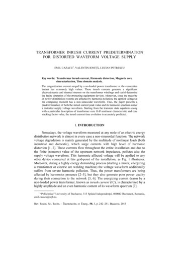
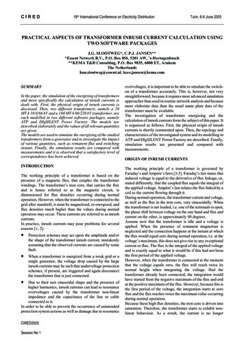
International Journal of Engineering Trends and Technology (IJETT) – Volume 33 Number 1- March 2016connected in delta, or by using interposing CTs orspecial connection of main CTs (Guzman, et al.,2002).Figure 1: Differential protection of 3-phaseStar/Delta Transformertrip. Security of transformer differential protectionschemes is dependent on detecting the magnetizinginrush currents of the protected transformer andassociated blocking of differential operation due toinrush related, non-fault, unbalance currents. Theinrush waveform is highly distorted and rich inharmonics. The evaluation of harmonic content inthe energization currents has been the primarymeans of inrush detection in transformer differentialrelays for many years. The transient generates acurrent known as inrush current. The magnitude ofthis inrush current can be several times the loadcurrent and flows only on one side of the differentialrelay, which tends to operate if some form ofrestraint is not provided. Figure 2 shows a typicalcurve of inrush current due to the energization of apower transformer. The vast majority of transformerdifferential relaying schemes use the amount ofharmonic content of the measured waveform todetermine that an energization is taking place. Thenormal differential element is blocked for thiscondition. Faults during energization are detected bysupervising the restrained element with anunrestrained element, set above the largest expectedenergization magnitude.This is to ensure that the phase shifts created in thecurrents of the power transformer are compensatedby the CTs, so that the secondary currents are onceagain in phase. This provides a zero sequencecurrent circulating path within the currenttransformers connection so that it cannot flow in therelays. Figure 1 show the connections of adifferential protection scheme with Star / Delta CTs.a) Energization of TransformerEnergization of transformer is a typical event wheremagnetizing inrush currents are of concern. Theexcitation voltage on one winding is increased from0 to full voltage. The transformer core typicallysaturates, with the amount of saturation determinedby transformer design, system impedance, theremnant flux in the core, and the point on the voltagewave when the transformer is energized.An external fault may significantly reduce thesystem voltage, and therefore reduce the excitationvoltage of the transformer. When this fault is cleared,the excitation voltage returns to the normal systemvoltage level (Blackburn and Thomas, 2007). Thereturn of voltage may force a dc offset on the fluxlinkages, resulting in magnetizing inrush current.This magnetizing inrush current will be less than thatof energization, as there is no remnant flux in thecore. The current measured by the differential relaywill be fairly linear due to the presence of loadcurrent, and may result in low levels of secondharmonic current.Transformer energization creates a true unbalance,but is not a fault, and the differential relay must notISSN: 2231-5381Figure 2: Typical magnetizing inrush current in apower transformerThresholds for defining energization generally havebeen fixed between 12% and 32%, depending onrelay type. Undesired operations of differentialrelays during energization have been encountered bymany utilities. Historically (in the electromechanicalimplementation), transformer differential relays havebeen applied as single-phase elements, with aseparate relay for each set of transformer windings.Phase shift compensation was accomplished throughthe CT connections. Inrush detection was limited toevaluating the harmonic content of the currentsavailable within the specific relay element. One ofthe complications of energization currents is thattransformer inrush is not a consistent condition. Thecurrents will vary from one energization to the next.http://www.ijettjournal.orgPage 28
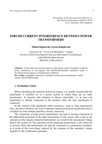
International Journal of Engineering Trends and Technology (IJETT) – Volume 33 Number 1- March 2016The energization currents are not equally distributedbetween the individual windings. This cancomplicate the process of identifying inrush in arelay system, if a specific phase does not havesufficient harmonic content to be recognized asenergization.i.Harmonic Restraint and BlockingTechniquesIn the harmonic restraint element, the operatingcurrent, IOP, must overcome the combined effects ofthe restraining current, IRT, and the harmonics of theoperating current for the element to assert a tripoutput. Any measurable harmonic content providessome benefit toward the goal of preventingdifferential relay operation during inrush conditions.On the other hand, in the harmonic blocking element,the operating current is independently comparedwith the restraint current and those selectedharmonics when the harmonic content is above aspecified threshold. When the harmonic content isbelow the specified threshold, the harmonic blockinghas no effect. The selection of harmonics, and thevariables used to compare harmonics with theoperate current in either a harmonic blocking orharmonic restraint relay, are crucial to the successfuloperation of either type of scheme. Generally,harmonic blocking or harmonic restraint elementsare successful if they fulfill all of the followingrequirements:Permit fast tripping for all internaltransformer faults with minimal delay whenenergizing a faulted transformerPrevent transformer differential nt differential element operationduring transformer energization and duringvoltage recovery following a power systemfaultThe magnetizing inrush currents have highcomponent of even and odd harmonics (Guzman etal., 2002).ii. Advantages of Microprocessor-BasedDifferential Relay ProtectionHigh stability against CT saturationprovided by integrated saturation detectorand add-on stabilization.Highly stabilize against inrush currents dueto advanced filter technology (Fourieranalysis) and optional cross-blockingfunction.High stability against over-excitation (5thharmonic blocking).Short tripping time - typically 1.5 cyclesISSN: 2231-5381 High set differential current (Iop) fasttripping 1 cycleMicroprocessor-Based Relays offer many otherfeatures that electromechanical relays do not offersuch as fault locating, event reporting, advancedmetering functions and control capability. The eventrecord provides data on the internal relay elementoperation and the currents and voltage waveforms atthe time of operation. This is similar to having afault recorder on every breaker where amicroprocessor-based relay is installed. The eventdata is an invaluable tool in evaluating relay andsystem performance.All of the waveformspresented in this paper are derived from relay datarecording.III. Material and MethodsMicroprocessor-based differential relays incorporatesecond harmonic restraint feature (magnetizinginrush currents). Harmonics restrain is based on thefact that the inrush current has a large secondharmonic component of the differential currentwhich is much larger in the case of inrush than for afault. The over-excitation current also rmonics are used to restrain the relay fromtripping during these conditions. Modern relays usesecond and fifth harmonics for restraint so that therelay is prevented from tripping for inrush and overexcitation, but is not blocked from tripping forinternal faults with CT saturation.In harmonic sharing technique, the incomingcurrents are filtered to extract the fundamentalsignals (for faults and load) and the second harmonicsignal (for inrush). The overall inrush signals (2ndharmonic) are then summed to create a singleharmonic signal, representing the overall inrushcurrents as shown in figure 3.Figure 3: Circuit Diagram of Harmonic (blocking) InhibitThe inhibit threshold is adjusted to accommodate thelarger overall signal resulting from the summing.Rather than using 12% independent harmonic, 18%summed harmonic was used. Each phase element ofhttp://www.ijettjournal.orgPage 29
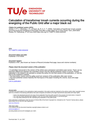
International Journal of Engineering Trends and Technology (IJETT) – Volume 33 Number 1- March 2016the 87T function compares its specific fundamentalcurrent with the summed harmonic signal and makesan independent decision whether to inhibit forenergization. This provides improved security forsituations with unreliable harmonic content.Sensitivity was maintained for faults during inrushconditions, as the fundamental current in the faultedphase (unbalance) easily override the sum of thesecond harmonic currents associated with energizingthe unfaulted phases.Two case studies are presented to clarify thesepoints. Each was taken from data records frommicroprocessor-based relay systems, with the dataexported from COMTRADE format, and importedinto Excel spreadsheets.IV. ANALYSIS AND RESULTSCase study #1: Transformer Energization:The waveform in figure 4 shows an energization of athree phase 33/11kV, 15MVA D-Y connectedtransformer with internally compensated recorded bya digital relay. The transformer was energized fromthe high voltage side, with the secondary side open.The secondary circuit currents (LV side) are zero, sothe primary circuit currents will ref
current circulating path within the current transformers connection so that it cannot flow in the relays. Figure 1 show the connections of a differential protection scheme with Star / Delta CTs. a) Energization of Transformer Energization of transformer is a typical event where magnetizing inrush currents are of concern. The excitation voltage on one winding is increased from 0 to full voltage .