Transcription
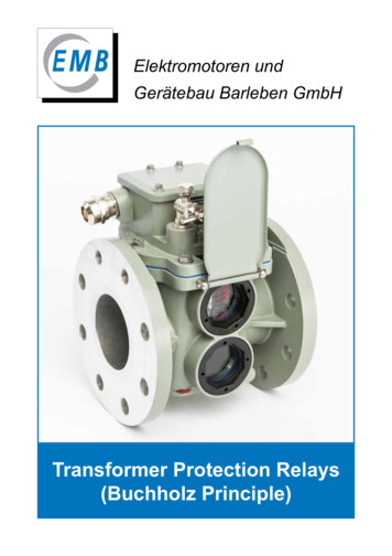
Elektromotoren undGerätebau Barleben GmbHTransformer Protection Relays(Buchholz Principle)
Elektromotoren und Gerätebau Barleben GmbHTable of contentsPage2Company history 41Preface 52Design features 63Function 83.1Gas accumulation 83.2Insulating liquid loss 93.3Insulating liquid flow 94Tests 105Type list of single-float Buchholz relays 115.1Single-float Buchholz relays with threaded connection 115.2Single-float Buchholz relays with flanged connection 115.3Single-float Buchholz relays with flat flanged connection 126Switching system design options for single-float Buchholz relays 137Type list of double-float Buchholz relays 147.1Double-float Buchholz relays with threaded connection 147.2Double-float Buchholz relays with flanged connection (round) 157.3Double-float Buchholz relays with flat flanged connection (round) 177.4Double-float Buchholz relays with flanged connection (square) 187.5Double-float Buchholz relays with geometrical flange dimensionsaccording to Chinese norm 187.6Double-float Buchholz relays with geometrical flange dimensionsaccording to former French norm 197.7Double-float Buchholz relays with geometrical flange dimensionsaccording to former British standard 208Switching system design options for double-float Buchholz relays 219Technical data 26
10Options/Special designs 2710.1Explanations to code 17 A 2910.2Explanations to codes 23 and 24/24B 2910.3Explanations to code 32 3011SMART-Buchholz relay 3111.1 Explanations to code 60 - Gas volume sensor - NM series 11.1.1Construction of Buchholz relay with gas volume sensor 3211.1.2Additional function of Buchholz relay with gas volume sensor 3211.1.3Analog measuring device - analog gas volume measurement 3311.2 Explanations to code 61 - Buchholz relay with temperature sensor 3411.2.1Construction of Buchholz relay with temperature sensor 3411.2.2Additional function of Buchholz relay with temperature sensor 3411.3 Explanations to code 62 - Buchholz relay with moisture-temperature sensor 12323511.3.1Construction of the Buchholz relay with moisture-temperature sensor 3511.3.2Additional function of the Buchholz relay with moisture-temperature sensor 35Ordering data/Type code 3612.1 Single-float Buchholz relays 3612.2 Double-float Buchholz relays 3712.3 Ordering example 3813Additional devices for Buchholz relays 3913.1 Gas sampling device ZG 1.2. 3913.2 Other additional devices for Buchholz relays 4314Other protection devices 4515Breathing Buffer Box 473
Elektromotoren und Gerätebau Barleben GmbHCompany historySince its foundation the company has passed through an eventful history with regard to ownership,affiliation and change of name associated with such development.1863Foundation of the company as sugar factory1921Development of Buchholz relay by Max Buchholz1943Branch of SIEMENS Magdeburg1948VEB Elektromotorenwerk Barleben; VEM(state-owned firm)1951VEB Starkstromanlagenbau Magdeburg(state-owned firm)1951Start of manufacture of Buchholz relays in Barleben1965Start of manufacture of monitoring relays for tap changers in Barleben1970VEB Elektrotechnik und Gerätebau Magdeburg; EGEM(state-owned firm)1980VEB Kombinat Elektromaschinenbau DresdenVEB Elektromotorenwerk Barleben; VEM; ELMO(state-owned firm)1990VEM Antriebstechnik AG DresdenElektromotorenwerk Barleben GmbH; VEM; ELMO(public limited company)1993Elektromotoren und Gerätebau Barleben GmbH; EMB(privately owned company)2005Start of manufacture of Buchholz relays NM series2009New premises in Barleben2015Acquisition of the Buchholz relay production line from Koncar CroatiaFigure 1 - EMB company building4
1PrefaceMore than 1.5 million relayshave been sold worldwide in 60 years!The Buchholz relay was developed in 1921 by Max Buchholz, Oberrat (senior councillor) at PreußischeElektrizitäts-A.G. (Prussian electricity company) in Kassel. Since that time it has been an importantprotection and monitoring device for insulating liquid filled transformers with conservator and chokecoils. It also allows separate monitoring of oil-filled bushings or cable terminal boxes. It is mounted inthe cooling cycle of the device to be protected and responds to faults such as gas generation, lossof as well as high flow rates of the insulating liquid.For transformers with hermetical closure by means of a hydro-type compensator (rubber sack) in theconservator, the Buchholz relay can be used also a monitoring device (air cell failure relay) of thehydro-type compensator.The Buchholz relay is suitable for open-air as well as indoor installations.The type diversity of the Buchholz relay is tailored to norms and standards as well as to specialcustomer demands. The type of relay to be used depends on the nominal rating and constructionfeatures of the device to be protected. Our range of products permits optimum adaptation to actualrequirements.Elektromotoren und Gerätebau GmbH (EMB GmbH) provides more than 60 years experience inproducing Buchholz relays and other protective devices for liquid-cooled and liquid-insulated devices.It ranks today among the most distinguished manufacturers of this type of equipment.EMB Buchholz relays are in compliance with EN 50216-2 and are known for their easy operation,high reliability and extremely long life.Our staff of highly qualified engineers and experienced skilled workers do their best to guaranteetop-quality high-precision products. The casings are machined on modern CNC-controlled machines.All products are subjected to final inspection when all functions are checked using special testequipment.Profound experience and expertise in this special area are a sound basis for high product quality.Extensive references from reputed transformer manufacturers as well as other users are proof of thehigh qualitative level of the products.EMB has been certified according to: DIN EN ISO 9001:2015, AEO F, Known Consignor (AirfreightSecurity) and EAC. Further certifications have been awarded by well-known independent testlaboratories such as TÜV Rheinland and TZO.Figure 2 - Certificates5
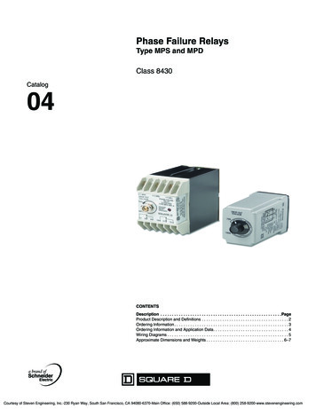
Elektromotoren und Gerätebau Barleben GmbH2Design featuresCasingThe casing is made of weather-resistant cast aluminium alloy provided with a paint coat. It is suppliedeither with flanged (Fig. 3/ Number 1) or threaded connection (Fig. 3/ No.2). The different casingdesigns available are shown in Section 5 for single-float Buchholz relays and Section 7 for doublefloat Buchholz relays, others are available on request.To check the switching system for proper function, the casing is provided with sightglasses (Fig. 3/No. 3). The sightglasses provided with scales permit reading of collected gas volume.The relays can be provided with hinged lids (Fig. 3/ No.4) to protect the sightglasses.1342Figure 3 - Figure 3 - Casing with flanged connection, left, and threaded connection, right6
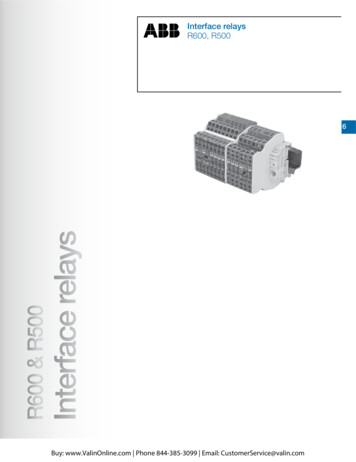
CoverThe cover is made of weather-resistant cast aluminium alloy provided with a paint coat. The uppersection of the cover accommodates the terminal box (Fig. 4/ No. 1). In front of the terminal box arearranged the bleeding valve (Fig. 4/ No. 2) and the test key covered by a cap nut (Fig. 4/ No. 3) as wellas a plate (Fig. 4/ No. 4) with instructions for actuating the test key. The terminal box accommodatesthe earth terminal (Fig. 4/ No. 5) and bushings (Fig. 4/ No. 6) for the terminals provided in the baseof the cover. The number of these bushings determines the design of the switching systems in termsof type and quantity of the magnet contact tubes.The terminal box is sealed by an cap (Fig. 4/ No. 7) so that it is safe to touch and protectedagainst pollution. If the cap is opened instructions for installation (Fig. 4/ No. 8) are shown e.g. thegraphic symbol and the connection diagram. The cable can be inserted through the cable gland(Fig. 4/ No. 9).785961324Figure 4 - Top view of Buchholz relay with cap removed, left with six magnet contact tubes andright with four magnet contact tubes7
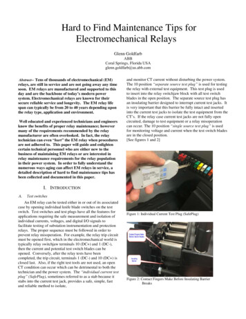
Elektromotoren und Gerätebau Barleben GmbH3FunctionThe Buchholz relay is installed in the pipe between the tank of the device to be protected (transformer,reactor) and the conservator. During normal operation it is filled completely with insulating liquid.Due to buoyancy the float of the single-float relay and both floats of the double-float relay are at theirtop position.The upper and lower switching systems form a functional unit in the single-float Buchholz relay sothat in the event of a fault the transformer is immediately disconnected from the power system.In the following the function of a Buchholz relay is explained using the example of a double-floatBuchholz relay. If a fault occurs inside the transformer, the Buchholz relay responds as follows:3.1Gas accumulationFault: Free gas is available in the insulating liquid.Response: The gas in the liquid moves upwards, accumulates in the Buchholz relay and displacesthe insulating liquid level. As the liquid level falls, the upper float moves downwards.The moving float actuates a switch contact (magnet contact tube). An alarm signal is tripped.The lower float is not affected as from a certain gas volume the gas flows through a piping to theconservator.GasGasOilÖlFigure 5 - Gas accumulation8
3.2Insulating liquid lossFault: Insulating liquid loss due to leakage.Response: As the liquid level falls, the conservator, piping and Buchholz relay are emptied. First, thetop float lowers and causes an alarm signal. When now the loss of liquid continues, the lower floatsinks and actuates a switch contact so that the transformer is shut down.AirLuftOilÖlFigure 6 - Insulating liquid loss3.3Insulating liquid flowFault: A spontaneous incident generates a pressure wave moving in the direction of the conservator.Response: The liquid flow reaches the damper arranged in the liquid flow. If the flow rate exceedsthe operating value of the damper, the latter moves in flow direction.Due to this movement a switch contact is actuated so that the transformer is disconnected.After release of the pressure wave the lower switching system returns to its starting position.Buchholz relays manufactured by EMB are equipped with a damper held by a permanent magnet.OilÖlFigure 7 - Insulating liquid flow9
Elektromotoren und Gerätebau Barleben GmbH4TestsEach Buchholz relay is provided with a works-number that is specifiedon the test certificate and the name plate. The tests carried out on theBuchholz relay are recorded in the test certificate.- Dielectric strength test- Leakage test- Functional test- Flow test.Buchholz relays are delivered in cardboard boxes.For each relay delivered the following documentsin the language agreed are provided:- Operating instructions- Test certificate.Note: Flange gaskets are not included in the scope of delivery!The name plate covers the following information:date of manufacture(week/year)Typetype codeworks-no.6 digitsswitchingIP codeelementS normally-openÖ normally-closedW change-overFigure 8 - Functional and leakage test10Figure 9 - Flow test
55.1Type list of single-float Buchholz relaysSingle-float Buchholz relays with threaded connectionType(Internal description)(Former DINdesignation)Type of connection01(AG 25)(CG 25)ThreadedconnectionG 1½ “PipediameterDN 16185170623,1Flange dimensions(mm)Device dimensions(mm)Suited fortransformerratings of 1600 KVAFigure 10 - Dimensional drawing, type 015.2Single-float Buchholz relays with flanged connectionType(Internal description)(Former DINdesignation)Type of connection02(AF 25/6)(-)03(AF 25/10)(-)PipediameterDN 4-hole2510075601212185195623,6 1600 KVAFlange4-hole2511585681416200205624,0 1600 KVAFlange dimensions(mm)Device dimensions(mm)Suited fortransformerratings ofFigure 11 - Dimensional drawing, type 02, 0311
Elektromotoren und Gerätebau Barleben GmbHType(Internal description)(Former DINdesignation)Type of connection25(AF 25)(-)Flange4-holePipediameterDN 5-M1215160195623,3 1600 KVASuited fortransformerratings of 1600 KVAFlange dimensions(mm)Device dimensions(mm)Suited fortransformerratings ofFigure 12 - Dimensional drawing, type 255.3Single-float Buchholz relays with flat flanged connectionType(Internal description)(former DINdesignation)Type of connection30(AF 25/10 G)(-)Flange4-holeFigure 13 - Dimensional drawing, type 3012PipediameterDN 5-1416200205624Flange dimensions(mm)Device dimensions(mm)
6Switching system design options for single-float Buchholz relaysMagnet contact tubes are used as switching elements. These are normally-open (NO), normallyclosed (NC) and change-over (CO) contacts. The magnet contact tube design can be derived fromthe last digit of the type code. For coding, see Ordering data/Type code under Section 12.1.1.2.3.4.5.61 NO1 NC2 NO2 NC1 NO and1 NC1 CO131113231121131114121424122214122.7.8.92 CO1 NO and 1 CO3 NO2122124 121114Explanation of symbols:2324 124111414 13 24233433Example: coding „ . 6 “Magnet contact tube(s) design1241 COGraphic symbol with terminal markingConnection diagram in terminal boxThe inner side of the cap accommodates a plate with the graphic symbol and the connectiondiagram. The schemes show the switching systems in their neutral position. The neutralposition is the operating condition when the Buchholz relay is filled with insulating liquid upthe required level and the device to be protected operates without any fault.13
Elektromotoren und Gerätebau Barleben GmbH77.1Type list of double-float Buchholz relaysDouble-float Buchholz relays with threaded connectionType(Internal description)(Former DINdesignation)Type of connection04(BG 25)(DG 25)21(BG 25 dedconnectionG 1½ “25----16185235904,2 5000 KVAThreadedconnectionG 1½ “25----16185235903,6 5000 KVAFigure 14 - Dimensional drawing, type 04Figure 15 - Dimensional drawing, typ
Transformer Protection Relays (Buchholz Principle) Elektromotoren und Gerätebau Barleben GmbH. 2 Eletromotoren und Gertebau arleben Gmb Table of contents Page Company history 4 1 Preface 5 2 Design features 6 3 Function 8 3.1 Gas accumulation 8 3.2 Insulating liquid loss 9 3.3 Insulating liquid flow 9 4 Tests 10 5 Type list of single-float Buchholz relays 11 5.1 Single-float Buchholz relays .