Transcription
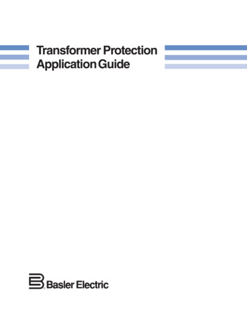
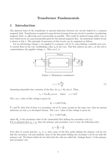
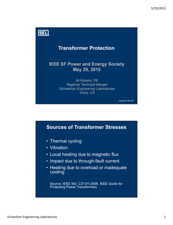
5/29/2015Transformer ProtectionIEEE SF Power and Energy SocietyMay 29, 2015Ali Kazemi, PERegional Technical MangerSchweitzer Engineering LaboratoriesIrvine, CACopyright SEL 2015Sources of Transformer Stresses Thermal cyclingVibrationLocal heating due to magnetic fluxImpact due to through-fault currentHeating due to overload or inadequatecoolingSource: IEEE Std. C37.91-2008, IEEE Guide forProtecting Power TransformersSchweitzer Engineering Laboratories1
5/29/2015Transformer Failure Statistics1983–1988 Winding failures Tap changer failures Bushing failures37%22%11% Terminal board failures3% Core failures1% Miscellaneous failures26%Source: IEEE Std. C37.91-2008, IEEE Guide for Protecting Power TransformersTransformer Protection Differential Protection Current Transformer Performance Through Fault Protection Mechanical ProtectionSchweitzer Engineering Laboratories2
5/29/2015Design Considerations forTransformer Differential Protection Differential pickup CT ratio and CTsettingsvoltage class selection CT connections Current phase shiftsacross transformer Inrush detection Zero-sequencecurrents Slope High excitation currentsDesign Considerations forTransformer Backup Protection Overcurrent Directional overcurrent External faults Sudden pressure Hot spots Loss of coolersSchweitzer Engineering Laboratories3
5/29/2015Differential Protection OvercurrentBalanced CT RatioCTCTProtectedEquipmentNormal Load50IOP 0Differential ProtectionSchweitzer Engineering Laboratories4
5/29/2015Common Problems WithDifferential ProtectionCTProtectedEquipment50CTExternalFaultIOP 0 False differential current can occur if CT saturates duringthrough fault Some measure of through current can be used todesensitize relay when high currents are presentDifferential Current and CT SaturationSchweitzer Engineering Laboratories5
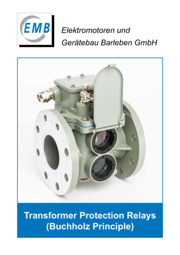
5/29/2015Possible Solution PercentSlope y(87)Compares:IOP IS IRk IRT k IS IR2Dual-Slope Differential Digital RelayIOPUnrestrainedPickup, IHSOperatingRegionMinimumPickup, IPUSlope 1IR1Schweitzer Engineering LaboratoriesSlope 2RestrainingRegionIR2IR3IRT6
5/29/2015Adaptive Slope for SecurityIOPOperateSlope 2External Fault87PSlope 1Internal FaultRestrainIRTDifferential Protection Summary Overcurrent differential scheme is simpleand economical but does not respond wellto unequal CT performance Percentage differential scheme respondsbetter to CT saturation Differential principle provides best protectionselectivity and speedSchweitzer Engineering Laboratories7
5/29/2015Current TransformersCurrent Transformer (CT) Principle CT isolates relayfrom the HV system Drastically reducescurrentIdeally: is ip / NsSchweitzer Engineering Laboratories8
5/29/2015Core and Secondary WindingExampleThe Current Transformer EquivalentCircuitSchweitzer Engineering Laboratories9
5/29/2015Induced Secondary Voltage Assuming the CT is not saturated, and magnetic fluxdensity (B) is sinusoidal:B Bmax sin t BA ABmax sin t Induced secondary voltage is approximately:Vs 2 fN s ABmax 4.44 f N s ABmax2 Note: If Bmax, Ns, and f are fixed, the only way to obtainlarger induced voltages is to make A larger. This implies alarger iron core.Excitation Curve for a C400 MultiratioCTSchweitzer Engineering Laboratories10
5/29/2015Core-BalanceCurrent ce CTWhich Photo Shows Correct Installation?Schweitzer Engineering Laboratories11
5/29/2015CT Burden CalculationIPIS VS –ZLEADSCT Terminal VoltageVS IS ZB IS ZLEADS ZDEVICE ZDEVICEANSI Standard Terminal Voltage Rating Defines minimum CT terminal voltage for 20 times nominal current Standard burden 10% ratio error Applies to full winding Using CT taps reduces accuracySchweitzer Engineering Laboratories12
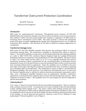
5/29/2015C Class Terminal Voltage RatingVSTD 20 IS RATED ZB STDFor IS RATED 5 A secondaryC ClassZB STD (Ω)VSTD (V)C1001100C2002200C4004400C8008800Avoiding CT Saturation forAsymmetrical Faults2 –Rt VS 2IF ZB e L – cos t 1.5vS10.50–0.5–10Schweitzer Engineering Laboratories0.020.040.06Time (s)0.080.113
5/29/2015Avoiding CT Saturation forAsymmetrical FaultsIF per-unit fault currentZB per-unit burdenPredicting CT Saturation inAsymmetrical Faults C400, 2000/5 CT with 1 burden ZB 1 ZB STD 4 Maximum asymmetrical fault current forX/R 12: IFmax 20 / 0.25 (12 1) 6.15 pu 12.3 kASchweitzer Engineering Laboratories14
5/29/2015IF ZB(1 X/R) 20IF ZB(1 X/R) 50Schweitzer Engineering Laboratories15
5/29/2015Common CT ConnectionsWyeDeltaIaIaIbIbIcIcIas Ibs IcsIresIas – IcsIcs – IbsIbs – IasEffective Burden Depends on CTConnections and Fault TypesEffective Burden Impedance (ZB) forDifferent Types of FaultsCT ConnectionWyeDeltaSchweitzer Engineering LaboratoriesThree Phase orPhase to PhasePhase to GroundZLEADS ZDEVICE2 ZLEADS ZDEVICE3 (ZLEADS ZDEVICE) 2 (ZLEADS ZDEVICE)16
5/29/2015Select CT That Will Not Saturate Know maximum available symmetrical faultcurrent (use VS VSTD and IFZB 20 toverify no saturation) Determine X/R ratio and worst-caseasymmetrical fault (use IFZB (X/R 1) 20to determine CT will not saturation underasymmetrical fault conditions)Determine Maximum EmergencyRating of Transformer Calculate full load rating (FLA) of transformer Ensure CTR matches FLA as closelyas possibleSchweitzer Engineering Laboratories17
5/29/2015DABY or DY1 Transformer ConnectionYDAC or YD1 Transformer ConnectionSchweitzer Engineering Laboratories18
5/29/2015Traditional Compensation I– Ib N2 / N1 I– Ic N2 / N1 I– Ia N2 / N1 abc Ia Ib IcN2 11 N1 CTR1 CTR2 I– Ia N2 / N1 / CTR1 Ic– Ia / CTR2 I I – I N Ib– Ic / CTR2cba– Ic N2 / N1 / CTR1b2/ N1 / CTR1 Ia – Ic / CTR2Compensation With Digital RelaysCurrent Scaling and Phase-ShiftCompensation Are Internal Exact current scaling Phase-shift compensation for all transformerconnections Allowed wye-CT connectionSchweitzer Engineering Laboratories19
5/29/2015Current Scaling With Digital RelaysDigital relays can fully compensate forcurrent amplitude differencesDigital Relays Allow Connection ofCTs in WyeABCH1Winding 1Winding 2X1H2X2H3X3abcICW1 ICW2IBW1 IBW2IAW1 IAW2Schweitzer Engineering Laboratories20
5/29/2015Current Scaling and ent for anExternal Fault87Delta compensationremoveszero-sequencecurrentSchweitzer Engineering ZS2ZT2ZeroSequenceZS0ZT021
5/29/2015Zero-Sequence Current RemovalTraditional RelaysAuxiliary CTs connected aszero-sequence trap87Zero-Sequence Current RemovalDigital Relay1TAP1Schweitzer Engineering Laboratories1TAP222
5/29/2015Differential Current Caused byMagnetizing Inrush, Overexcitation,and CT SaturationMagnetizing Inrush Current ObtainedFrom Transformer TestingSchweitzer Engineering Laboratories23
5/29/2015Inrush Current Harmonic ContentHarmonic-Based Methods in a RelayWith Three Differential Elements Independent harmonic restraint Independent harmonic blocking Common harmonic blockingSchweitzer Engineering Laboratories24
5/29/2015Harmonic-Based Method ComparisonFeatureIndependent EvenHarmonic RestraintCommon EvenHarmonic BlockingSecurity forexternal faultsHighHighSecurity for inrushHighHighDependabilityHighHighSpeed for internal faultsLowerHigherSpeed for internal faultsduring energizationHigherLowerSlope characteristicAdaptiveFixed(harmonic dependent) (harmonic independent)Combined Harmonic Blocking andRestraint for Optimal Protection Faults during inrush conditions Faults during normal conditionsSchweitzer Engineering Laboratories25
5/29/2015Harmonic Restraint Mode Operation conditions IOP IPU IOP SLP IRT K2I2 K4I4 Blocking condition (K5I5 IOP)Application ConsiderationsSchweitzer Engineering Laboratories26
5/29/2015Selection of Characteristic Settings Minimum pickup: constant differential current Slope 1: proportional differential current Slope 2: CT saturationConstant and ProportionalDifferential Currents Constant Exciting current (1 to 4% of rated current) Unmonitored load in protection zone Proportional Tap mismatch: 0% in digital relays Tap changers: NLTC 5%; LTC 10% Linear CT errors: 3% Relay errors: 5%Schweitzer Engineering Laboratories27
5/29/2015DO NOT DELETECombinedTransformerBus andFeederSchweitzer Engineering Laboratories28
5/29/2015Results of Repeated Faults andMechanical StressesTransformer Overcurrent andMechanical Protection Apply overcurrent protection forthrough-fault damage to transformers Review IEEE thermal model Understand how sudden pressure relaysprovide sensitive protection for turn-to-turnfaults and how to apply themSchweitzer Engineering Laboratories29
5/29/2015Overcurrent Protection Possible primary protection for smalltransformers Backup of primary protection (87 and 63) Backup protection for faults in adjacentprotection zones (trip transformer before itis damaged)Transformer Damage Curves Infrequent fault incident curve (fewer than5 faults in life of transformer) Use infrequent fault curve For faults in zones that are cleared byhigh-speed protection For systems without overhead linesSchweitzer Engineering Laboratories30
5/29/2015Category IVAbove 10,000 KVA –single phaseAbove 30,000 KVA –three phaseSource: IEEE Std. C57.12.00-2010, IEEE Standard forStandard General Requirements for Liquid-ImmersedDistribution, Power, and Regulating TransformersIEEE Standard C57.91-2011Guide for Loading MineralOil-Immersed Transformers Top-oil temperature Hottest-spot temperature Loss of lifeSchweitzer Engineering Laboratories31
5/29/2015Transformer Cooling System Contact inputs indicate active coolingsystem status Thermal model selects constants for threecooling systems Oil-air (OA) Forced-air cooled (FA) Forced oil-air (FOA)Transformer Thermal MonitoringOptimizes Operation Transformer protection System operation System planning Capital investmentSchweitzer Engineering Laboratories32
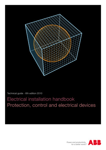
5/29/2015Mechanical ProtectionSudden Pressure Relay (ANSI 63) Gas space (sudden pressure) Under oil (fault pressure)Qualitrol Rapid Pressure Rise Relay(Under-Oil Type)Schweitzer Engineering Laboratories33
5/29/2015Combine Relays for BestTransformer Protection Differential relay is primary protection formost faults in tank and bus work Sudden pressure relay is primary protectionfor turn-to-turn faults and backup 87 forlarge faults inside tank Overcurrent relays are primary protectionfor through-fault damage and providebackup for faults in tank and bus workQuestions?Schweitzer Engineering Laboratories34
Source: IEEE Std. C57.12.00-2010, IEEE Standard for Standard General Requirements for Liquid-Immersed Distribution, Power, and Regulating Transformers IEEE Standard C57.91-2011 Guide for Loading Mineral Oil-Immersed Transformers Top-oil temperature Hottest-spot temperature Loss of life. 5/29/2015 Schweitzer Engineering Laboratories 32 Transformer Cooling System Contact inputs .File Size: 1MBPage Count: 34