Transcription
3Dissimilar MaterialsWeldability ConceptsDecember 15, 2015Dr. Alber SadekTechnology Lead – Materials EngineeringEWIasadek@ewi.org614.688.5125
4Introduction Dissimilar materials welding refers to the joining of: Two different alloy systems (e.g., steel, stainless steel) Materials of different fundamental types Metals, ceramics, polymers, composite Ferrous to non-ferrous Materials with different compositions within a particular type(e.g., austenitic stainless steel, ferritic stainless steel, duplexstainless steel, etc.). Importance to industry: Dissimilar lightweight material welding is used to connectdifferent metals together for automotive industries Used where an object is subjected to multiple environments inone application such as in chemical and petrochemicalindustries, power generation, and oil and gas industries Minimize costs of fabrication.
5Advantages Each section of the welded component can beoptimized for its specific application.Provide damage tolerance to the overall structure.Optimize design by matching the correct material tothe needed property or behavior.High performance materials only used where theyare absolutely required and provide real benefit.
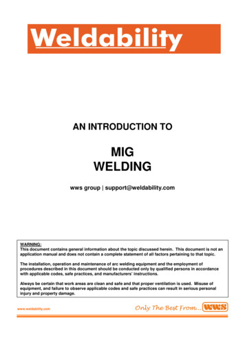
6Disadvantages Weld metal consists of a mixture of materials whichhave unknown material properties when combinedwith unevenly distributed heating or stresses.WeldMetalBronze ElectrodeCarbon orLow Alloy SteelStainless SteelCopperButtering LayerJoint PartsMaterialThermalExp./Cont Coeff.(1/K) x 10-6StainlessSteel316 L194284Weld Metal308 L192984Buttering309 L194095Alloy SteelA 516 G60122960 - 80YS(ksi)UTS(ksi)ButteringLayer ofPure NiCopperCarbon orLow Alloy SteelSteel ElectrodeCarbon orLow Alloy Steel
7Metallurgical Processes Metallurgically, all fusion welds are dissimilar metalwelds because: Weld zone has a cast solidified structure, while the base metalhas a wrought structure The chemical composition of deposited weld metal is overmismatch or under-mismatch to that of the base metal based onthe required joint strength.
8Challenges of WeldingDissimilar Metals The existence of a transition zone between themetals and the intermetallic compounds formed inthe heat affected zone: If there is mutual solubility of the two metals, the dissimilar jointscan be made successfully If there is little or no solubility between the two metals to bejoined, the weld joint will not be successful. The formation of intermetallic compounds and theireffects on: Increasing the crack sensitivity Reducing the ductility Increasing the susceptibility to corrosion.
9Challenges of WeldingDissimilar Metals Differences in the coefficient of thermal expansion: The residual stresses in welds are generated by the thermalcontraction of the weld metal and the adjacent base metal. As aresult, the residual stress distribution and magnitude are notsimilar across the dissimilar weld joint If these are widely different, there will be internal stresses set upin the inter-critical HAZ leading to service failure. The difference in melting temperatures, since onemetal will be molten and overheated before the otherwhen subjected to the same heat source.The difference of the electrochemical potential couldincrease the susceptibility to corrosion at HAZ. Ifthey are far apart on the scale, corrosion can be aserious problem.
10DifficultiesDifference inM.P, T.C, ,EFormation ofBrittleIntermetallicPhasesFormation ofOxide LayerJoiningTechniquesofDissimilarJointsHybrid StructurePoorSolubility inEach Other
11Relative Properties of DifferentMaterialsMaterialMeltingPoint( F)Mild BTU.In/ft2.h. F)7.862750AHSS7.87230-3607.78StainlessSteel .77Nickel BaseAlloys2300 24408.197.852.71
12Weldability Weldability is the capacity of a material to be welded under thefabrication conditions imposed, into a specific, suitablydesigned structure, and to perform satisfactorily in the rocessParametersPerformanceDesignResponse to Stressand Strain DuringWeldingMechanical, Physicaland ChemicalProperties of theWelded Joint
13Classification of Weld JointDiscontinuities It is unusual for the weldments to be completely sound.They normally contain small defects.Welding Processor Procedure-RelatedDiscontinuities Porosity, slag, oxideinclusions, lack offusion, undercut,crack, distortion,etc. MetallurgicalDiscontinuitiesDesign RelatedDiscontinuities Cracks or fissures(hot, cold, reheat,lamellar) Microstructuralalterations at HAZ Weld metal & HAZsegregation Base platelaminations Changes in section& other stressConcentrators Weld joint typeUnderstandthe CauseSolve/Preventthe ProblemFurthermore, different metals have different weldability, so we need tounderstand the nature of the metal to be welded.
14Weldability of Metals and Alloys Weldability of carbon steel alloys is inversely proportional toits hardenability due to martensite formation.Austenitic stainless steels tend to be the most weldable, butsuffer from distortion due to high thermal expansion leadingto cracking and reduced corrosion resistance.Ferritic and martensitic stainless steels are not easilywelded, often to be preheated and use special electrodes.Aluminum alloys are susceptible to hot cracking, oxideinclusions, dross, and porosity (hydrogen).Titanium alloys with low amounts of alloying elements aremore readily welded, while highly stabilized titanium alloysare difficult to weld due to segregation.
Questions?
Case StudiesDissimilar Joining of Carbon Steel to Stainless Steel
17DifficultiesA risk of martensite formation in the weldafter dilution by the base metal and residualamounts of ferrite resulting in possible hotcracking. The deposition of carbon steel or low-alloysteel filler metal on austenitic stainless steelcan result in hard, brittle weld deposits. Hot cracking may occur because of lowmelting point impurities such as phosphorous(P) and sulfur (S).
18DilutionBADilution A / (A B) 100%ConsumableConsumable80 %20 %80 %Base MetalSquare GrooveMetal A10 %V GrooveMetal B10 %Consumable70 %30 %Base MetalSurfacing
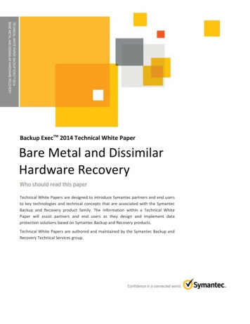
19Schaeffler DiagramSchaeffler diagramindicates theapproximatemicrostructure forhigh-alloyed steelwelds.
20Area of Schaeffler DiagramA AusteniteM MartensiteF Ferrite
21Cold Cracking Cold cracking or hydrogen-induced cracking are terms for thesame phenomena. Well-known types of cold cracks are: Under bead crack (base metal) Root crack Micro-crack or transverse crack in the weld metal. Martensitic structures are the most susceptible structure with thepresence of hydrogen and residual stresses.Cracks usually appear at weld temperatures below 200 C.Weld: To Avoid Martensitic StructuresSelection of consumables with minimummartensite in the as-weldedmicrostructure.Base Metal: To Avoid Cold Cracking Preheating, if necessary.
22Solidification Cracking Hot cracking refers to cracking that occurs duringwelding, casting, or hot working at temperatureclose to the melting point of the material.The cracking is known to occur both: above the liquation temperature known as super-soliduscracking and in solid state, called sub-solidus cracking. Super-solidus cracking may manifest as: Solidification cracking occurs in the presence of a liquid phase inthe fusion zone, or as Liquation cracking in the heat-affected zone where it isaccompanied by grain boundary melting. To Avoid Low Melting Constituents:Selection of consumables with at least 5 vol.-% ferritein the as-welded microstructure.
23Sigma Phase Sigma phase is intermetallic phase and it forms at temperaturesbetween 500 and 900 C in ferritic stainless steels containing morethan 14% Cr.The formation of sigma phase results in: Increased hardness ( sometimes useful) Decreased ductility Decreased corrosion resistance. Sigma phase embrittlement isa problem where longexposure at elevatedtemperature (welding of thicksections, heat treatments attemperatures between 500and 900 C) are involved.
24MaterialsASTM A 515 G60CSiMn0,20,40,6P0,01S0,01Austenitic stainless steel 316Chemical Composition nsumablesStandard ElectrodeAWS A5.1-91: E 7018-1 H4RAWS A5.4-92: E 318-17AWS A5.4-92: E 316L-17AWS A5.4-92: E 307-15AWS A5.4-92: E 309 L-17AWS A5.4-95: E 309 MoL-17 C0,07 0,03 0,030,10,020,02Chemical CompositionSi Mn CrNi0,5 1,10,8 0,8 19,0 11,50,8 0,8 18,8 11,70,7 6,5 18,8 8,80,7 0,7 23,0 12,50,7 0,8 23,0 12,5(%)Mo2,72,7Nb0,352,7The fusion ratio between base material and consumable is 20:80Which electrodes are useable to join the dissimilar materials?
25A515G60St.St.316E 7018-1 H4RA515G60St.St.316E 4.602.65Nieq6.3014.6015,05Dilution (20%)Creq 2.83Nieq 4.21Dilution (20%)Creq 14.13Nieq 18.11
26A515G60St.St.316E 309 L-17Creq0.6021.7024,05Nieq6.3014.6013,45Dilution (20%)Creq 12.85Nieq 21,47A515G60St.St.316E 309 MoL-17Creq0.6021.7026,75Nieq6.3014.6015,0Dilution (20%)Creq 12.89Nieq 23,63
27Electrode SelectionAWS A5.1-91: E 7018-1 H4RCreq2.83Weld MetalNieq4.21F%0Cold crackingAWS A5.4-92: E 318-1712.0920.699GoodAWS A5.4-92: E 316L-1712.2520.397AWS A5.4-92: E 307-1514.1318.110AWS A5.4-92: E 309 L-1712.8521,478AWS A5.4-95: E 309 gmaembrittlementStandard ElectrodeEvaluation
Questions?
Case StudiesDissimilar Joining of Steel to Aluminum
30MaterialAluminumSteel
31Characteristics Macrostructureand Microstructure (Al side)Advance SideAlRetreat SideOOOOFeHAZ 1 mmStirred Zone100 mCharacteristic microstructures observed in different areas on Alside of FSW joint (RT 41.7 s-1 Vr 3.3 mm/s).HAZ
32Characteristics Macrostructureand Microstructure (steel side)Advance SideRetreat SideAlFe1 mmFine Grain Zone HAZ100 mCharacteristic microstructures observed in different areas onsteel side of FSW joint (RT 41.7 s-1 Vr 3.3 mm/s).
33Effect of Rotation Speed onFine Grain Size of SteelAverage GrainSize is 3 mRT 25.0 s-1Vr 3.3 mm/sAverage GrainSize is 6 mAverage GrainSize is 4.7 mRT 33.3Vr 3.3RT 41.7Vr 3.3Increasing Rotation Speed50 µm
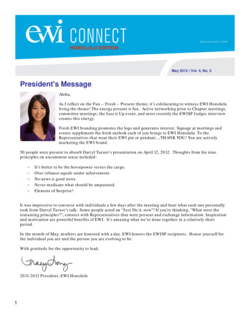
Microstructure and Hardness ofInterlayer34AluminumSteelAluminum29 3031 30Steel31 31 173 168 136 115 1170.5 mm423150 mLayer StructureRT 33.3 s-1Vr 3.3 mm/sElementsFeAl 18020(at%)Points23457 78 9843 22 2Layer structure and EDX analyses at some points.376Aluminum269Steel50 m Hardness values forthe layered structure.
35X-ray Diffraction PatternRT 41.7 s-1Vr 3.3 mm/s Al Fe Al5Fe2 Al13Fe4 Careful adjustment of FSW parameters, avoids the formation ofthe layered structure and results in good joint quality.
Questions?
Case StudiesDissimilar Welding of Nodular Cast Iron to Steel
38Problems This type of dissimilar metal weldments areparticularly characterized by: Compositional gradient and microstructural changes, whichproduce large variations in chemical, physical, and mechanicalproperties across the weldment Further complexity arises with the addition of filler metal, whichis a common practice in dissimilar metal welding The formation of carbides during solidification and the formationof martensite during solid-state transformation.
39MaterialsdLCastIron L Carbon910 C Steel Fe3CL Fe3CCast Irona 723 CaCarbonSteel0%a Fe3C0.8% 2%Iron Carbon Diagram Coefficient of Linear Expansion Steel: 12.1 x 10⁻⁶ / oCCast Iron: 10.8 x 10⁻⁶ / oCNickel: 13.3 x 10⁻⁶ / oC
40Cracking Tendency Cracking tendency at HAZ increases incase of welding without buttering layer.WZHAZ
41Hardness MeasurementWithout ButteringLayerWith ButteringLayer
42Mechanical PropertiesType ofElectrodeUTS(MPa)ENi-C1330 – 420ENi-Fe-C1370 - 450E7018350 - 420Type of rodeLocation ofFailureCast IronHAZUTS(MPa)Locationof FailureWMHardness(Hv)Cast Iron SideSteel Side175 – 210535203180 – 260440208160 - 190350180WMHardness(Hv)Max. HAZ Hardness (Hv)Max. HAZ Hardness (Hv)Cast IronSideSteel SideENi-C1437 – 476200237176E7018379 – 386180240161ENi-Fe-C1436 – 468230260180E7018380 - 396180252172Cast Iron
43SummaryMetallurgicallyDissimilar metal welding requires consideration of all the basicfactors found in conventional welding. On the other hand, thedifference of the base metal and weld metal chemistry should beprecisely analyzed.PerformanceThe mechanical and physical properties, microstructuralstability, and resistance to oxidation and corrosion of theweld metal as well as those of both heat-affected zonesshould be suited for the intended service.Selection of Welding ConsumablesThe best selection results in a jointwhich has an acceptable range ofdilution and metallurgical compatibilityto achieve the required properties.Welding ProcessSelecting the welding process is a key factor whenwelding dissimilar metals, since the heat input affectsdilution, alloy element migration, and residual stresscaused by differences in the thermal coefficient.SuccessfulDissimilarMetal Joint
44Material Engineering GroupAlber Sadek, Ph.D.George Ritter, Ph.D. Technology Lead Material characterization,welding metallurgy (ferrous andnonferrous alloys), failureanalysis and trouble shooting Principal Engineer Adhesive bonding systems andprocesses. Bonding of dissimilarmetals and ceramics forlightweight structures and armor asadek@ewi.org 614.688.5125 gritter@ewi.org 614.688.5199Kirk CooperWesley Wang, Ph.D. Senior Engineer Diffusion bonding, brazing, andsoldering of ferrous, nonferrousand ceramics materialsMaterials and process selection Senior Engineer Shipbuilding, offshoreengineering, welding consumabledes
Technology Lead – Materials Engineering EWI asadek@ewi.org 614.688.5125. 4. Introduction. Dissimilar materials welding refers to the joining of: Two different alloy systems (e.g., steel, stainless steel) Materials of different fundamental types. Metals,