Transcription
TRAININGGUIDEMILL-LESSON-FBM-2FBM MILL AND FBM DRILL
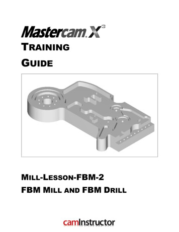
Mastercam Training GuideObjectivesThis lesson will use the same Feature Based Machining (FBM) methods used in Mill-LessonFBM-1, how ever this time applying FBM to much more complex geometry. Using similarconfigurations techniques as the previous lesson, you will see advantages in programming timeusing the FBM toolpaths.Feature Based Machining (FBM)FBM eliminates manual featureidentification for programming millingand drilling operations on solid parts.The FBM Mill and FBM Drill operationsautomatically create the toolpathsneeded to machine features that areidentified using your specific criteria.FBM's interface is simple and intuitive.You will generate the toolpaths for MillLesson-FBM-2 to machine the part on aCNC vertical milling machine.This Lesson covers the following topics:Establish Stock Setup settings:Stock size.Material for the part.Feed calculation.Generate a 2-dimensional milling toolpath consisting of:FBM Mill operation and child toolpath operations.FBM Drill operation and child toolpath operations.Inspect the toolpath using Mastercam’s Verify by:Launching the Verify function to machine the part on the screen.Saving the FBM Mill results as an in-process STL in Verify.Applying the FBM Drill results to the in-process stock definition.Comparing the machined stock to the part geometry.Generating the NC- code.Mill-Lesson-FBM-2 - 1
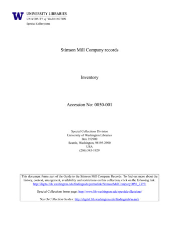
Mill-Lesson-FBM-2MILL-LESSON-FBM-2 DRAWINGSMill-Lesson-FBM-2 - 2
Mastercam Training GuideMill-Lesson-FBM-2 - 3
Mill-Lesson-FBM-2Mill-Lesson-FBM-2 - 4
Mastercam Training GuideMill-Lesson-FBM-2 - 5
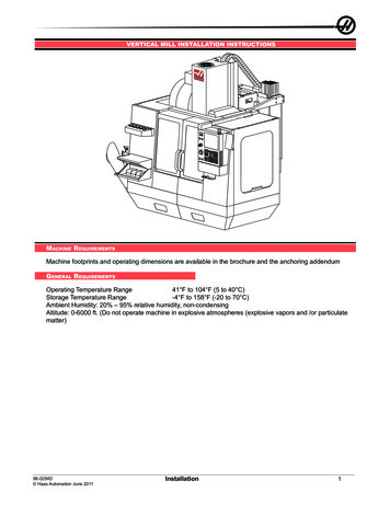
Mill-Lesson-FBM-2TOOL LIST6.0” face mill1.0” diameter flat end mill0.75” diameter flat end mill0.625” diameter flat end mill0.5” diameter flat end mill0.375” diameter flat end mill0.25” diameter flat end mill0.125” diameter flat end mill0.5” spot drill1/2”-13 UNC tap0.4219” drill0.375” drill3/8”-16 tap0.3125” drillMill-Lesson-FBM-2 - 6
Mastercam Training GuideMill-Lesson-FBM-2 - 7
Mill-Lesson-FBM-2Mill-Lesson-FBM-2 - 8
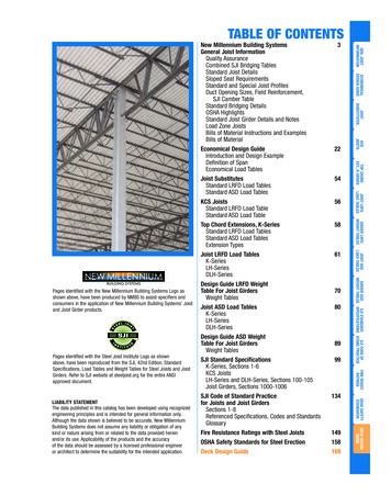
Mastercam Training GuideMILL-LESSON-FBM-2 - THE PROCESSToolpath CreationTASK 1: Import part geometry from Parasolid fileTASK 2: Setting the environmentTASK 3: Save part geometry for later inspectionTASK 4: Define the rough stock using stock setupTASK 5: Run FBM Mill for all milling operationsTASK 6: Verify the toolpath, comparing results to partgeometry, and saving out in-process stockTASK 7: Run FBM Drill for all hole making operationsTASK 8: Verify the toolpath using saved stockTASK 9: Save the updated MCX fileTASK 10: Post and create the CNC code fileTASK 1:IMPORT PART GEOMETRY FROM PARASOLIDIn this lesson you will use an imported solid model.1. Click on File Open2. Beside Files of Type click on the drop down arrow and select Parasolid Files(*.X T;*.X B;*.XMT TXT)Mill-Lesson-FBM-2 - 9
Mill-Lesson-FBM-23.On the multimedia CD that came with this text is a folder called Mastercam-Filesbrowse to this location and select MILL-LESSON-FBM-2.X T4. Select the green check mark buttonto load the file and complete this function.5. Press and hold the Alt key on your keyboards and type s to toggle shading in Mastercam.This Key mapping shortcut is often denoted as Alt S .6. Select the Screen Fit icon found at the top of the screen to fit the part to the screen7. For a better view of the part use the toolbar at the top of the screen to change the graphicsview to Isometric. Review the features that make up this part.8. Press and hold the Alt key on your keyboards and type s to toggle wireframe in Mastercam.9. Change the graphics view to the Top View by using the toolbar at the top of the screen.10. Select the Screen Fit icon found at the top of the screen to fit the part to the screen11. The screen should look like the one below:Mill-Lesson-FBM-2 - 10
Mastercam Training Guide12. Select File Save as 13. In the File name box, type Mill-Lesson-FBM-2.14. Save to an appropriate location.15. Select the green check mark buttonto save the file and complete this function.TASK 2:SETTING THE ENVIRONMENTBefore starting the geometry import you should set up the grid, toolbars and machine typeas outlined in the Setting the environment section at the beginning of this text:1. Set up the Grid. This will help identify the location of the origin.2. Customize the toolbars to machine a 2D part.3. Set the machine type to a Haas Vertical Spindle CNC machine.TASK 3:SAVE PART GEOMETRY FOR LATER INSPECTION1. Select File Save as 2. Beside Save as type: click on the drop down arrow and select StereoLithography Files(*.STL)STL files are used with StereoLithography systems.An STL file comprises triangular facets of data that representsurface and solid models.Mastercam can read and write both binary and ASCII STLfiles.3. In the File name box it should read Mill-Lesson-FBM-2.4. Save to an appropriate location – typically C:\Mcamx\data for STL files5. Select the green check mark buttonto save the file and complete this function.Mill-Lesson-FBM-2 - 11
Mill-Lesson-FBM-2Toolpath CreationTASK 4:DEFINE THE ROUGH STOCK USING STOCK SETUPDefining the Rough Stock using stock setup.1. Fit to screen using the Key mapping shortcut Alt F1 2. Select the plus in front of Properties to expand the Toolpaths Group Properties. Alt O will Show/hide Operations Manager pane.3. Select Stock setup in the toolpath manager window as shown above on the right:The bottom face of the material has been pre-machined and is not part of the toolpathoperations for this lesson.The instructions for this lesson require plus 0.1” stock on thickness, and additional stock inlength and width is left to our discretion.Z zero is at the bottom of the part.4. From the Machine Group Properties Stock Setup tab, select the Bonding box button5. You will create stock from All Entities with Expand entries of 0.25 in X and Y, and .1 in Z.6. Select the green check mark buttonto close this dialog box.Mill-Lesson-FBM-2 - 12
Mastercam Training Guide7. Expand adds stock values to each face. In order to remove the additional .1” from thebottom of the stock – the pre-machined face – change the Z thickness value to 3.1”8. Select the Tool Settings tab and change the parameters to match the Tool Settingsscreenshot below. To change the Material type, follow the next set of instructions.9. To change the Material type to Aluminium 6061 pick the Select button at the bottom of theTool Settings pageMill-Lesson-FBM-2 - 13
Mill-Lesson-FBM-210. As you change the Feed Calculation to From Material you will be prompted to pick amaterial from the Material List dialog box. Change the Source to Mill - library11. From the Default Materials list select ALUMINIUM inch - 6061 and then select.With the selection of Feed Calculation From material in the Machine Group PropertiesTool Settings tab, all feeds and speeds are set based on calculated values.Many users take the time to create a custom tool library with only their tools, with desiredfeeds and speeds set in the library.Feeds and speeds can be edited in the resulting FBM child operations if desired.12. Select the OK buttonagain to complete this Stock Setup function.Mill-Lesson-FBM-2 - 14
Mastercam Training GuideTASK 5:RUN FBM MILL FOR ALL MILLING OPERATIONSIn this task you configure settings in FBM Mill to set up tools and interrogate the solid tocreate machining regions and apply toolpath strategies.FBM Mill pays close attention to flute length during automatic tool selection. If allowing the useof Tools from library, shorter library tools will be selected for shallow pockets. When the pocketdepth exceeds the flute length of the library tool, a longer tool with the same diameter will becreated to achieve the required depth of cut.In this exercise we will allow FBM Mill to generate all tools as required to machine the partgeometry. In order to avoid multiple same diameter tools, we will avoid the use of library tools.1. From the menu bar select Toolpaths FBM Mill 2. On the screen you will now see the FBM Toolpaths – Mill dialog box, starting with theSetup page. From this page you will select Create as needed to have FBM Mill inform us ofthe tools required to complete machining of the part. You will also elect to rough and finishthe outside of this part. Your selections should appear as follows:Tool numbering will appear to be non-sequential. Tools are created with the length required forthe pocket being processed. If an identical diameter tool is required to be longer for a deeperpocket, the original tool will be replaced with a longer tool, but will have a higher tool numberthan the original.Mill-Lesson-FBM-2 - 15
Mill-Lesson-FBM-23. Click on Feature detection in the Tree Control menu on the left hand side of the dialog box.4. You will leave the default settings, which should be as follows:5. You will skip past the Preferred tool list for Facing tools, Roughing tools, Restmill tools,and Finish tools.6. Next you will set Facing cut parameters, selecting Facing from the Tree Control dialog box,and adjusting settings for 1 rough cut, and selecting Zigzag.To force a single facing depth cut, your selections should be set as follows:Mill-Lesson-FBM-2 - 16
Mastercam Training Guide7. Next you will set Roughing cut parameters, selecting Roughing from the Tree Control dialogbox, and adjusting settings for Helical entry, 75% of diameter XY Stepover, 25% ofdiameter Depth Cuts, and 0.015” Stock to leave on walls. Your selections should be setas follows:8. Next you will set Restmill cut parameters, selecting Restmill from the Tree Control dialogbox, and adjusting settings for 75% of diameter XY Stepover, 25% of diameter Depth Cuts,and 0.015” Stock to leave on walls. Your selections should be set as follows:Mill-Lesson-FBM-2 - 17
Mill-Lesson-FBM-29. Select Floor Finish from the Tree Control dialog box and uncheck Enable floor finishin order to disable floor finishing.10. Next you will set Finish cut parameters, selecting Wall Finish from the Tree Control dialogbox, and adjusting settings for 1 Finish Pass, 1 Depth Cut, and Tangent Entry / Exitmoves with lines and arcs that are 50% of the tool’s diameter. Your selections should beset as follows:11. Select Linking Parameters from the Tree Control dialog box. You will use a Clearancevalue of 2” above the Stock model, with 0.1” Retract and Feed plane values:Mill-Lesson-FBM-2 - 18
Mastercam Training Guide12. Select Coolant from the Tree Control dialog box. Set Flood to On:to process all milling operations for this part.13. Select the OK button14. When prompted to Enter new NC name ensure Mill-Lesson-FBM-2 is displayed and thenselect the OK button.15. Process times can be significant for complete geometry, so be patient.16. For a better view of the part use the toolbar at the top of the screen to change the graphicsview to Isometric and activate a screen fit.17. Your screen should appear as the one below:Mill-Lesson-FBM-2 - 19
Mill-Lesson-FBM-2TASK 6:VERIFY THE TOOLPATH, COMPARING RESULTS TO PARTGEOMETRY, AND SAVING OUT IN-PROCESS STOCKMastercam's Verify utility allows you to use solid models to simulate the machining of a part.The model created by the verification represents the surface finish, and shows collisions, ifany exist.This allows you to identify and correct program errors before they reach the shop floor.1. In the Toolpath Manager pick all the operations to verify by picking the Select All icon2. Select the Verify selected operations button circled below:3. Select the Turbo mode.4. Adjust the speed to the far right along the speed control bar.5. Now select the Options button:Mill-Lesson-FBM-2 - 20.
Mastercam Training Guide6. Ensure that Use TrueSolid is selected along with Compare to STL file.7. Select the green check mark buttonto close this dialog box.to verify the toolpaths.8. Select the Fast Forward button9. When Verification is complete, the STL Compare window will open.10. Clickand select the file MILL-LESSON-FBM-2.STLto Compare the machined stock and the STL File.11. Click12. Cuts within tolerance are displayed in Green. The holes will appear as Blue as you have yetto process them. This check demonstrates that FBM Mill has addressed the features of thispart.to return to the Verify dialog box.13. Select the OK buttonMill-Lesson-FBM-2 - 21
Mill-Lesson-FBM-2The verified toolpaths are shown below.14. Select the Save stock as file button2 MILL.STL15. Select the OK button16. Select the OK buttonusing the filename –MILL-LESSON-FBM-to save the in-process part geometry.to exit Verify.TASK 7:RUN FBM DRILL FOR ALL HOLE MAKING OPERATIONSIn this task you configure settings in FBM Drill to interrogate the solid, identify hole features,and apply holemaking strategies.1. Change the graphics view to the Top View by using the toolbar at the top of the screen.2. Select the Screen Fit icon found at the top of the screen to fit the part to the screen3. From the menu bar select Toolpaths FBM Drill Mill-Lesson-FBM-2 - 22
Mastercam Training Guide4. On the screen you will now see the FBM Toolpaths – Drill dialog box, starting with theSetup page selected in the Tree Control menu down the left hand side:5. From this page you will change the Sorting option by click on the current Sorting methodicon6. Select the Point to Point 2D Sort Method7. Select the OK buttonin the 2D sort page.Mill-Lesson-FBM-2 - 23
Mill-Lesson-FBM-28. The prompt now changes to Select sorting start point. Move the mouse and position thecursor over the point at the center of circle shown below, you will notice this iconappears as you move over the point at the center of this circle. This cross denotes you aresnapping to a circle center point. Use the left button of your mouse to pick this point.9. Select Hole Detection from the Tree Control dialog box and set parameters to Includeblind hole and to Limit search to plane TOP as follows:Mill-Lesson-FBM-2 - 24
Mastercam Training Guide10. Select Deep Drilling from the Tree Control dialog box and check Deep drilling11. Select Spot Drilling from the Tree Control dialog box and check Spot drilling.Mill-Lesson-FBM-2 - 25
Mill-Lesson-FBM-212. Select Pre-drilling from the Tree Control dialog box and check Pre-drilling.The 3/8-16 UNC tapped holes will require Pre-drilling with a 5/16” drill. You will use anAdditional break through of .1” for this part which features all through holes.13. Select Tools from the Tree Control dialog box. You will allow FBM Drill to automaticallyCreate as needed by applying the follow settings:Mill-Lesson-FBM-2 - 26
Mastercam Training Guide14. Select Linking Parameters from the Tree Control dialog box. This dialog box will be usedto set our Clearance at Solid height plus 1.”, Retract at Solid height plus 0.1”, anAdditional break through of .1”, and No adjustment for the Tap / Ream adjustment forthis part which features all through holes.15. Select Coolant from the Tree Control dialog box. Set Flood to On:16. Click the Detect. button at the top of the FBM Toolpaths – Drill dialog box.Mill-Lesson-FBM-2 - 27
Mill-Lesson-FBM-217. Your screen should appear as follows:18. Left click on the first 0.375 Dia. / 1.75 Depth Hole the list.19. Press and hold the Shift key on your keyboard. Left click on the last 0.375 Dia. / 1,75 DepthHole in the list. Release the Shift key. This will select all rows from the first mouse selectionthrough the second mouse selection.Mill-Lesson-FBM-2 - 28
Mastercam Training Guide20. Right click on any of the selected rows, in the Hole type column who’s value currently readsDrill. Hover the cursor over Hole type and select TAP RH from the list.21. Using the same selection method, pick the three .5 Dia. Holes and set to Tap RH.22. A 1/2”-12 UNS tap is selected. Right click in the Finish tool column over one of three 1/2”taps, and select Finish tool XLS: TAP RH, 1/2-13 UNC, 0.5 OD, Pilot 0.4218.FBM Drill hole features are controlled by the file FbmToolTable.xls in the Mcamx\common\FBMdirectory. This file can be edited to offer additional selections.If you have SolidWorks installed on your system and have imported a .SLDPRT file, you canreselect the file from the FBM Drill Features page and update the features list with importedSolidWorks Hole Wizard data.23. Select the OK buttonto process all holemaking operations for this part.Mill-Lesson-FBM-2 - 29
Mill-Lesson-FBM-2TASK 8:VERIFY THE TOOLPATH USING SAVED STOCKMastercam's Verify utility allows you to use solid models to simulate the machining of a part.The model created by the verification represents the surface finish, and shows collisions, ifany exist.This allows you to identify and correct program errors before they reach the shop floor.1. For a better view of the part use the toolbar at the top of the screen to change the graphicsview to Isometric.2. Select the Screen Fit icon found at the top of the screen to fit the part to the screenIn the Toolpath Manager left click only on the FBM Drill Toolpath Group.3. Select the Verify selected operations button circled below:4. Now select the Options button:Mill-Lesson-FBM-2 - 30
Mastercam Training Guide5. In the Verify Options change the Stock selection to File. Also disable Compare to STLfile. Select MILL-LESSON-FBM-2.STL as your Stock file.to close this dialog box.6. Select the green check mark button7. Adjust the Verify speed to midway along the speed control bar.8. Select the play button to verify the toolpaths.Mill-Lesson-FBM-2 - 31
Mill-Lesson-FBM-2The verified toolpaths are shown below.9. Select the OK buttonto exit Verify.TASK 9:SAVE THE UPDATED MCX FILE1. Select File.2. Select Save.TASK 10:POST AND CREATE THE CNC CODE FILE1. Ensure all the operations are selected by picking the Select All iconmanager.from the Toolpath2. Select the Post selected operations button from the Toolpath manager.3. Please Note: If you cannot see G1 click on the right pane of the Toolpath manger windowand expand the window to the right.Mill-Lesson-FBM-2 - 32
Mastercam Training Guide4. In the Post processing window, make the necessary changes as shown below:5. Select the OK buttonto continue.6. Ensure the same name as your Mastercam part file name is displayed in the NC File namefield as shown below:7. Select the Save button.Mill-Lesson-FBM-2 - 33
Mill-Lesson-FBM-28. The CNC code file opens up in the default editor:9. Select thein the top right corner to exit the CNC editor.This completes Mill-Lesson-FBM-2.Mill-Lesson-FBM-2 - 34
Mill-Lesson-FBM-2 Mill-Lesson-FBM-2 - 10 3. On the multimedia CD that came with this text is a folder called Mastercam-Files browse to this location and select MILL-LESSON-FBM-2.X_T 4. Select the green check