Transcription
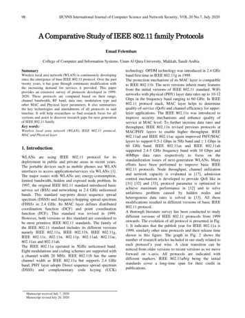
2IEEE/ACM TRANSACTIONS ON NETWORKING, VOL. 12, NO. 1, FEBRUARY 2004Measuring ISP Topologies With RocketfuelNeil Spring, Ratul Mahajan, David Wetherall, and Thomas AndersonAbstract—To date, realistic ISP topologies have not been accessible to the research community, leaving work that depends ontopology on an uncertain footing. In this paper, we present new Internet mapping techniques that have enabled us to measure routerlevel ISP topologies. Our techniques reduce the number of requiredtraces compared to a brute-force, all-to-all approach by three orders of magnitude without a significant loss in accuracy. They include the use of BGP routing tables to focus the measurements,the elimination of redundant measurements by exploiting properties of IP routing, better alias resolution, and the use of DNS todivide each map into POPs and backbone. We collect maps fromten diverse ISPs using our techniques, and find that our maps aresubstantially more complete than those of earlier Internet mappingefforts. We also report on properties of these maps, including thesize of POPs, distribution of router outdegree, and the interdomainpeering structure. As part of this work, we release our maps to thecommunity.Index Terms—Communication system operations and management, Internet, measurement, network reliability.I. INTRODUCTIONREALISTIC Internet topologies are of considerable importance to network researchers. Topology influences the dynamics of routing protocols [3], [11], the scalability of multicast[19], the efficacy of denial-of-service tracing and response [12],[18], [23], [24], and protocol design [20].Sadly, real topologies are not publicly available, because ISPsgenerally regard their router-level topologies as confidential.Some ISPs publish simplified topologies on the Web, but theselack router-level connectivity and POP structure and may be optimistic or out of date. There is enough uncertainty in the properties of real ISP topologies (such as whether router outdegreedistribution follows a power law as suggested by Faloutsos [8])that it is unclear whether synthetic topologies generated by toolssuch as GT-ITM [28] or Brite [14] are representative [27].The main contribution of this paper is to present new measurement techniques to infer high-quality ISP maps while usingas few measurements as possible. Our insight is that routinginformation can be exploited to select the measurements thatare most valuable. One technique, directed probing, uses BGProuting information to choose only those traceroutes that arelikely to transit the ISP being mapped. A second set of techniques, path reductions, suppress traceroutes that are likely toyield paths through the ISP network that have been already beentraversed. These two techniques reduce the number of traces reManuscript received November 13, 2002; approved by IEEE/ACMTRANSACTIONS ON NETWORKING Editor J. Rexford. This work was supported by the Defense Advanced Research Projects Agency under GrantF30602-00-2-0565.The authors are with the Department of Computer Science andEngineering, University of Washington, Seattle, WA 98195-2350USA (e-mail: nspring@cs.washington.edu; ratul@cs.washington.edu;djw@cs.washington.edu; tom@cs.washington.edu).Digital Object Identifier 10.1109/TNET.2003.822655quired to map an ISP by three orders of magnitude compared toa brute-force, all-to-all approach, without sacrificing accuracy.We also describe a new solution to the alias resolution problemof clustering the interface IP addresses listed in a tracerouteinto routers. Our new, pair-wise alias resolution procedure findsthree times as many aliases as prior techniques. Additionally, weuse DNS information to break the ISP maps into backbone andPOP components, complete with their geographical location.We used our techniques to map ten diverse ISPs—Abovenet,AT&T, Ebone, Exodus, Level 3, Sprint, Telstra, Tiscali (Europe), Verio, and VSNL (India)—using over 750 publiclyavailable traceroute sources as measurement vantage points.We summarize these maps in the paper.Three ISPs of the ten we measured helped to validate ourmaps. We also estimate the completeness of our maps by scanning ISP IP address ranges for routers that we might have missedand by comparing the peering links we find with those in BGProuting tables. Our maps reveal more complete ISP topologiesthan earlier efforts; we find roughly seven times more routersand links in our area of focus than a recent Skitter [7] dataset.As a second contribution, we examine properties that are ofinterest to researchers and likely to be useful for generating synthetic Internet maps. We characterize the distributions of routerand POP outdegree, and report new results for the distribution ofPOP sizes and the number of connections an ISP has with withother networks. All these distributions have significant tails.Finally, as one goal of our work and part of our ongoing validation effort, we have publicly released the ISP network mapsinferred from our measurements. The entire raw measurementdata is available to researchers; all our maps are constructed withend-to-end measurements and without the benefit of confidential information. The maps and data are available online [22].The rest of this paper is organized as follows. In Sections IIand III, respectively, we describe our approach and the mapping techniques. The implementation of our mapping engine,Rocketfuel, is described in Section IV. We present sampleISP maps and characterize their properties in Section V. InSection VI, we evaluate our maps for completeness and ourtechniques for their measurement efficiency and accuracy.We present related work in Section VII, and conclude inSection VIII.II. PROBLEM AND APPROACHThe goal of our work is to obtain realistic router-level mapsof ISP networks. In this section, we describe what we mean byan ISP map and the key measurement challenges we face.An ISP network is composed of multiple points of presenceor POPs, as shown in Fig. 1. Each POP is a physical locationwhere the ISP houses a collection of routers. The ISP backboneconnects these POPs, and the routers attached to inter-POP linksare called backbone or core routers. Within every POP, accessrouters provide an intermediate layer between the ISP backbone1063-6692/04 20.00 2004 IEEE
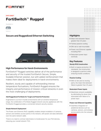
SPRING et al.: MEASURING ISP TOPOLOGIES WITH ROCKETFUEL3Fig. 2. Sample BGP table snippet. Destination prefixes are on the left,AS-paths on the right. ASes closer to the destination are to the right of the path.Fig. 1. ISP networks are composed of POPs and backbones. Solid dots insidethe cloud represent POPs. A POP consists of backbone and access routers(inset). Each traceroute across the ISP discovers the router-level path from thesource to the destination.and routers in neighboring networks. These neighbor routersinclude both BGP speakers and non-BGP speakers, with mostof them being non-BGP-speaking small organizations.Our aim is to discover ISP maps that consist of backbone, access, and directly connected neighboring domain routers and theIP-level interconnections between them. This constitutes the interior routing region of the ISP and its boundary “peering links.”ISPs are usually associated with their BGP autonomous systemnumbers (ASNs). The map we collect does not precisely correspond to the IP address space advertised by an AS. In particular,ISPs typically advertise the address space of non-BGP speakingcustomers as their own; our maps exclude such neighboring networks, consumer broadband, and dialup access networks. In thepaper, we use ISP names and their AS numbers interchangeably.Like earlier Internet mapping efforts [5], [7], [9], we discoverISP maps using traceroutes.1 This process is illustrated in Fig. 1.Each traceroute yields the path through the network traversedfrom the traceroute source to the destination. Traceroute pathsfrom multiple sources to multiple destinations are merged toform an ISP map. We use publicly available traceroute serversas sources. Each traceroute server provides one or more vantagepoints: unique traceroute sources that may be routers within theAS or the traceroute server itself.The key challenge is to build accurate ISP maps using fewmeasurements. We cannot burden public traceroute serverswith excessive load, limiting the traceroutes we can collectfrom each server. A brute-force approach to Internet mappingwould collect traceroutes from every vantage point to eachof the 120 000 allocated prefixes in the BGP table. If publictraceroute servers are queried at most once every 1.5 min,2 thisapproach will take at least 125 days to complete a map, a periodover which the Internet could undergo significant topologicalchanges. Another brute-force approach is to traceroute to all IPaddresses owned by the ISP. Even this approach is not feasiblebecause ISP address space can include millions of addresses,for example, AT&T’s 12.0.0.0/8 alone has more than 16 millionaddresses.1Using traceroute has inherent well-understood limitations in studying network topology. For example, traceroute does not see unused backup links in anetwork, it does not expose link-layer redundancy or dependency (multiple IPlinks over the same fiber), and it does not discover multi-access links.2This limit was provided by the administrator of one traceroute server, but isstill aggressive. Traceroutes to unresponsive destinations may take much longer.Our design philosophy is to choose traceroutes that will contribute the most information to the map and omit those that arelikely to be redundant. Our insight is that expected routing pathsprovide a valuable means to guide this selection. This trades accuracy for efficiency, though we will see that the loss of accuracy is much smaller than the gain in efficiency.After connectivity information has been obtained throughtraceroutes, two difficulties remain. First, each traceroute isa list of IP addresses that represent router interfaces. For anaccurate map, the IP addresses that belong to the same router,called aliases, must be resolved. When we started to constructmaps, we found that prior techniques for alias resolutionwere ineffective at resolving obvious aliases. In response, wedeveloped a new, pair-wise test for aliases that uses routeridentification hints such as the IP identifier, rate limiting, andTTL values.Second, to analyze the structural properties of the collectedmaps, we need to identify the geographical location of eachrouter and its role in the topology. Following the success ofrecent geographical mapping work [16], we leverage locationhints that are typically embedded in DNS names to extract thebackbone and the POPs from the ISP map.III. MAPPING TECHNIQUESIn this section, we present our mapping techniques, dividedinto three categories: selecting measurements, resolving aliases,and categorizing the role and location of ISP routers.A. Selecting MeasurementsWe use two classes of techniques to reduce the requirednumber of measurements. First, we select only traceroutesthat we expect will transit the ISP. We use a technique calleddirected probing that interprets BGP tables to identify relevanttraceroutes and prune the remainder. Second, we are interestedonly in the part of the traceroute that transits the ISP. Therefore,only one traceroute must be taken when two traceroutes enterand leave the ISP network at the same points. We use techniquescalled path reductions to identify redundant traceroutes.1) Directed Probing: Directed probing aims to identifytraceroutes that will transit the ISP network. Ideally, if we hadthe BGP routing table corresponding to each vantage point, wewould know the paths that would transit the ISP being mapped.Since these tables are not available, we use RouteViews [15]as an approximation. It provides BGP views from 60 differentpoints around the Internet.A BGP table maps destination IP address prefixes to a setof AS-paths that can be used to reach that destination. EachAS-path represents the list of ASes that will be traversed to reachthe prefix. We now show how to identify three classes of traceroutes that should transit the ISP network. In this example, weuse the BGP table snippet in Fig. 2 to map AS number 7.
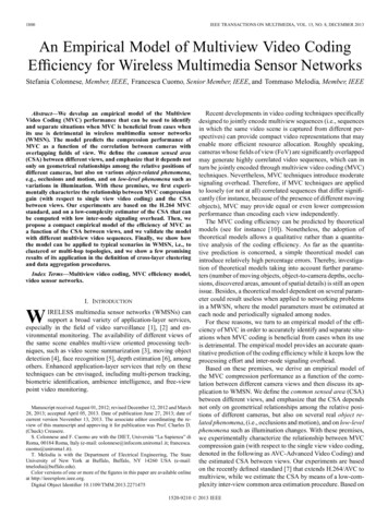
4IEEE/ACM TRANSACTIONS ON NETWORKING, VOL. 12, NO. 1, FEBRUARY 2004Fig. 4. Alias resolution. Boxes represent routers and circles representinterfaces. Traceroute lists input interface addresses from paths (left). Aliasresolution clusters interfaces into routers to reveal the true topology. Interfacesandare aliases (right).Fig. 3. Path reductions. (a) Only one traceroute needs to be taken perdestination when two servers (Ts) share an ingress. (b) Only one trace needs tobe taken when two dependent prefixes (Ps) share an egress router. (c) Only onetrace needs to be taken if two prefixes have the same next-hop AS number. Traceroutes to dependent prefixes: We call prefixes originated by the ISP or one of its singly-homed customers dependent prefixes. All traceroutes to these prefixes from anyvantage point should transit the ISP. Dependent prefixescan be readily identified from the BGP table: all AS-pathsfor the prefix would contain the number of the AS beingmapped. 4.5.0.0/16 is a dependent prefix of AS 7. Traceroutes from insiders: We call a traceroute server located in a dependent prefix an insider. Traceroutes frominsiders to any prefix should transit the ISP. Traceroutes that are likely to transit the ISP based on someAS-path are called up/down traces. In Fig. 2, a traceroutefrom a server in AS 11 to 1.2.3.0/24 is an up/down tracewhen mapping AS 7.Directed probing uses routing information to skip unnecessary traceroutes. However, incomplete information in BGP tables, dynamic routing changes, and multiple possible paths leadto two kinds of errors. Executed traceroutes that do not traverse the ISP (false positives) sacrifice speed, but not accuracy.Traceroutes that transit the ISP network, but are skipped becauseour limited BGP data did not include the true path (false negatives), may represent a loss in accuracy, which is the price wepay for speed. Traceroutes that were not chosen may traversethe same set of links seen by chosen traceroutes, so false negatives may not always compromise accuracy. In Section VI-B1,we estimate the level of both these types of errors.2) Path Reductions: Not all traceroute probes chosen bydirected probing will take unique paths inside the ISP. Therequired measurements can be reduced further by identifyingprobes that are likely to have identical paths inside the ISP.We examine where previous traces enter and exit the ISPnetwork to predict whether a future trace will take a new path.A fundamental assumption is that the path from entry to exit isconsistent. We list three techniques based on properties of IProuting to establish entry and exit points.Ingress Reduction. When traceroutes from two different vantage points to the same destination enter the ISP at the samepoint, the path through the ISP is likely to be the same. This isillustrated in Fig. 3(a). Since the traceroute from T2 to the destination would be redundant with the traceroute from T1, onlyone is needed. The observation is that traceroutes from a serverfrequently enter the ISP at only one router—other tracerouteservers that enter the ISP using the same router are equivalent.Egress Reduction. Conversely, if two destination prefixes arereached using the same egress router, they are equivalent: onlyone trace needs to be collected. This is illustrated in Fig. 3(b).Dependent prefixes are bound to egress routers in the egress discovery process described in Section IV. This prefix-to-egressrouter binding would be invalid for dependent prefixes originated by the ISP that connect in multiple locations. We expectthat such prefixes are few and that other prefixes are also connected to the same egress routers.Next-hop AS Reduction. When reaching prefixes outside theISP, the path usually depends only on the next-hop AS, and noton the specific destination prefix. Prefixes reached through thesame next-hop AS are thus equivalent, as shown in Fig. 3(c).Next-hop AS and egress reductions are similar in that they applyto the end of the path through the ISP. However, they are distinct in that there may be several peering points to the next-hopAS, while we expect only one egress router for ISP prefixes.Next-hop AS reduction applies to insider and up-down traces,while egress reduction applies to traces to dependent prefixes.Path reductions predict likely duplicates so that more valuabletraces can be taken instead without sacrificing fidelity. If theprediction is false (an unexpected ingress or egress was taken),we repeat the trace using other servers.B. Alias ResolutionTraceroute lists the source addresses of the “Time exceeded”ICMP messages; these addresses represent the link interfaces onthe routers that received traceroute probe packets. A significantproblem in recovering a network map from traceroutes is aliasresolution, or determining which interface IP addresses belongto the same router. The problem is illustrated in Fig. 4. If thedifferent addresses that represent the same router cannot be resolved, a different topology with more routers and links results.The standard technique for alias resolution was introduced byPansiot and Grad [17] and refined in the Mercator project [9]. Itdetects aliases by sending traceroute-like probes (to a high-numbered UDP port but with a TTL of 255) directly to the potentially aliased IP address. It relies on routers being configured tosend the “UDP port unreachable” response with the address ofthe outgoing interface as the source address: two aliases will respond with the same source. This technique is efficient in that itrequires only one message to each IP address, but we found thatit missed many aliases, at least for the ISPs we studied.Our approach to alias resolution combines several techniquesthat identify peculiar similarities between responses to packetssent to different IP addresses. These techniques try to collect evidence that the IP addresses are on the same router by looking for
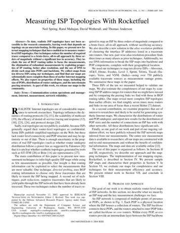
SPRING et al.: MEASURING ISP TOPOLOGIES WITH ROCKETFUELFig. 5. Alias resolution using IP identifiers. A solid arrow represents messagesto and from one IP, the dotted arrow the other.features that are centrally applied. We look primarily for nearbyIP identifiers, a counter that is stamped on responses by the hostprocessor. The IP identifier is intended to help in uniquely identifying a packet for reassembly after fragmentation. As such, itis commonly implemented using a counter that is incrementedafter generating a packet. This implies that packets sent consecutively will have consecutive IP identifiers.3 We also look for acommon source IP address in responses, as in Mercator. A thirdfeature is ICMP rate limiting, where the router’s host processorresponds only to the first of back-to-back probes.4 A fourth feature that is not sufficient on its own is the TTL remaining in theresponse. The TTL may start at different values depending onthe router operating system, and responses from routers in different locations are likely to traverse paths of different lengthback through the network. This makes the TTL useful for providing evidence that two addresses are not aliases, but the rangeof possible values is too small to show that addresses are aliases.The procedure for resolving aliases by IP identifier is shownin Fig. 5. Our tool for alias resolution, Ally, sends a probe packetsimilar to Mercator’s to the two potential aliases. The port unreachable responses include the IP identifiers and . Ally thensends a third and fourth packet to the potential aliases to collect identifiers and . If, andissmall, the addresses are likely aliases. In practice, some tolerance is allowed for reordering in the network. As an optimization, if, the aliases are disqualified and the thirdand fourth packets are not sent. In-order IP identifiers suggesta single counter, which implies that the addresses are likelyaliases. The results presented in this paper were generated usinga three-packet technique, without the packet, but we believethe fourth packet should further reduce the false positive rate.We observed that different routers change their IP identifiers atdifferent rates: the four-packet test establishes that the potentially two counters have similar value and rate of change, whilethe earlier three-packet test only demonstrated similar value.Some routers are configured to rate-limit port unreachablemessages. If only the first probe packet solicits a response, theprobe destinations are reordered and two probes are sent againafter five seconds. If, again, only the first probe packet solicits aresponse, this time to the packet for the other address, the ratelimiting heuristic detects a match. When two addresses appearto be rate-limited aliases, the IP identifier technique also detectsa match when the identifiers differ by less than 1000.3We have not observed routers that use random identifiers or implement thecounter in least-significant-byte order, though some do not set the IP ID at all.4We found that rate-limiting routers generally replied with the same sourceaddress and would be detected by Mercator.5Alias resolution using the IP identifier technique requiressome engineering to keep from testing every pair of IP addresses. We reduce the search space with three heuristics.First, and most effectively, we exploit the hierarchy embedded in DNS names by sorting router IP addresses bytheir (piecewise) reversed name. For example, names likechi-sea-oc12.chicago.isp.net and chi-sfo-oc48.chicago.isp.netare lexigraphically adjacent, and adjacent pairs are tested.Second, router IP addresses whose replies have nearby returnTTLs may also be aliases. Addresses are grouped by the TTLof their last response, and pairs with nearby TTL are tested,starting with those of equal TTL, then those within 1, etc. Of the16 000 aliases we found, 94% matched the return TTL, whileonly 80% matched the outgoing TTL (the TTL that remainedin the probe packet as it reached the router, which is includedin the response). Third, “is an alias for” is a transitive relation,so demonstrating that IP is an alias for IP , also demonstratesthat all aliases for IP are aliases for any of IP ’s aliases. Aliasresolution is complete when all likely pairs of IP addresses areresolved as aliases, not aliases, or unresponsive.There is a small probability that different routers will happento pick nearby identifiers. To remove the resulting false positives, we repeat the alias resolution test to verify the alias.C. Router Identification and AnnotationIn this section, we describe how we determine which routersin the traceroute output belong to the ISP being mapped, theirgeographical location, and their role in the topology.We rely on the DNS to identify routers that belong to the ISP.The DNS names provide a more accurate characterization thanthe IP address space advertised by the AS for three reasons.First, routers of non-BGP speaking neighbors are often numbered from the AS’s IP address space itself. In this case, theDNS names help to accurately locate the ISP network edge because the neighboring domain routers are not named in the ISP’sdomain (e.g., att.net). Some ISPs use a special naming convention for neighboring domain routers to denote the networkedge. For instance, small neighbors (customer organizations) ofSprint are named sl-neighborname.sprintlink.net, which is different from Sprint’s internal router naming convention. Second,edge links between two networks could be numbered from either AS’s IP address space. Again, DNS names help to identifythe network edge. Finally, DNS names are effective in pruningout cable modems, DSL, and dialup modem pools belonging tothe same organization as the ISP, and hence numbered from thesame IP address space. We resort to the IP address space criterion for routers with no DNS names (we observed very few ofthese), with the constraint that all routers belonging to the ISPmust be contiguous in the traceroute output.One of our goals was to understand the structure of ISPmaps, including their backbone and POPs. We identify the roleof each router as well as its location using the informationembedded in the DNS names. Most ISPs we studied have anaming convention for their routers that helps this effort. Forexample, sl-bb11-nyc-3-0.sprintlink.net is a Sprint backbone(bb11) router in New York City (nyc), and p4-0-0-0.r01.miamfl01.us.bb.verio.net is a Verio backbone (bb) router inMiami, Florida (miamfl01). We discover the naming convention of the ISP by browsing through the list of router names
6IEEE/ACM TRANSACTIONS ON NETWORKING, VOL. 12, NO. 1, FEBRUARY 2004TABLE ITHE NUMBER OF ROUTERS, LINKS, AND POPS FOR ALL TEN ISPS STUDIED.ISP ROUTERS INCLUDE BACKBONE AND ACCESS ROUTERS. WITH CUSTOMERAND PEER ROUTERS ADDS DIRECTLY CONNECTED CUSTOMER ACCESS ANDPEER ROUTERS. LINKS INCLUDE ONLY INTERCONNECTIONS BETWEENTHESE SETS OF ROUTERS. POPS ARE IDENTIFIED BY DISTINCT LOCATIONTAGS IN THE ISP’S NAMING CONVENTIONFig. 6. Architecture of Rocketfuel. The database (DB) becomes theinterprocess communication substrate.we gather. For some ISPs, we started with city codes from theGeoTrack database [16]. Some routers have no DNS names ortheir names lack location information. We infer the location ofsuch routers from that of its neighbors.IV. ROCKETFUELIn this section, we describe Rocketfuel, our ISP mappingengine. The architecture of Rocketfuel is shown in Fig. 6. APostgreSQL database stores all information in a blackboard architecture: the database provides both persistent storage of measurement results and a substrate for interprocess communicationbetween asynchronously running processes. The use of a database allows us to run SQL queries for simple questions and integrate new analysis modules easily.We used 294 public traceroute servers listed at traceroute.org[10], representing 784 vantage points all across the world.A traceroute server may be configured to generate traceroutes from many routers in the same autonomous system:oxide.sprintlink.net generates traceroutes from 30 vantagepoints. Most (277) public traceroute servers, however, supportonly one source.We now describe each module in Fig. 6. First, egress discovery is the process of finding the egress routers for dependentprefixes, which will be used for egress reduction. To find theegress routers, we traceroute to each dependent prefix from alocal machine. Because dependent prefixes may be aggregated,we break them into /24’s (prefixes of length 24, or, equivalently,256 IP addresses) before probing. We assume that breakingdown to /24’s is sufficient to discover all ISP egress routers.The tasklist generation module uses BGP tables from RouteViews [15] to generate a list of directed probes. The dependentprefixes in the directed probes are replaced with their egresses5and duplicates are removed. Tracing just to the egresses is anoptimization for speed; we avoid sending probes into customernetworks where they are likely to be filtered, which can slowtraceroute collection.Path reductions take the tasklist from the database, applyingress and next-hop AS reductions, and generate jobs forexecution. Information about traceroutes executed in the past isused by the path reductions module to determine, for example,which ingress is used by a vantage point. After a traceroute is5Theremay be several egresses for an aggregated prefix.taken, this module also checks whether the predicted ingressand egress were used. If so, the job is complete. Otherwise,another vantage point that is likely to take that path is tried.The execution engine handles the complexities of usingpublic traceroute servers: load-limiting, load-balancing, anddifferent formats of traceroute output. Load is distributedacross destinations by randomizing the job list, implementedby sorting the MD5 hash [21] of the jobs. We enforce a fiveminute pause between accesses to the same traceroute server toavoid overloading it. Traceroutes to the same destination prefixare not executed simultaneously to avoid hotspots.The traceroute parser extracts IP addresses that representrouter interfaces and pairs of IP addresses that represent linksfrom the output of traceroute servers. Often this output includespresentation markup like headers, tables, and graphics.V. ISP MAPSWe ran Rocketfuel to map ten diverse ISPs during December,2001, and January, 2002. In this section, we present summarymap information and samples of backbone and POP topology.The full map set, with images of the backbones and all the POPsof the ten ISPs, is available online [22]. We then analyze the ISPmaps to report their properties, with the goal of understandingtheir structure and engineering. We describe the sizes and composition of POPs, degree distributions over both the router-leveland backbone graph, and finally, the router-level adjacenciesthat make up inter-ISP peerings. We defer an evaluation of thevalidity of these maps to Section VI.A. Summary InformationThe aggregate statistics for all ten mapped ISPs are shown inTable I. The biggest networks, AT&T, Sprint, and Verio, are upto 100 times larger than the smallest networks we studied.B. BackbonesFig. 7 shows five sample backbones overlaid on a map of theU.S. Backbone design style varies widely between ISPs. We seethat AT&T’s backbone network topology includes hubs in majorcities and spokes that fan out to smaller per-city satellite POPs.In contrast, Sprint’s network has only 20 POPs in the U.S., all in
SPRING et al.: MEASURING ISP TOPOLOGIES WITH ROCKETFUEL7Fig. 8. Sample POP topology from Sprint in Springfield, Massachusetts. Thenames are prefixes of the full names, without sprintlink.net. Aliases for the samerouter are listed in the same box. Most POPs in Sprint are larger and too complexto show, but exhibit a similar structure.C. POPsUnlike the backbone designs, we found POP designs to be relatively similar
An ISP network is composed of multiple points of presence or POPs, as shown in Fig. 1. Each POP is a physical location where the ISP houses a collection of routers. The ISP backbone connectsthesePOPs,and theroutersattachedtointer-POPlinks are called backbone or core routers. Within every POP, access routers provide an intermediate layer between .