Transcription
TS-user manual 10th ED v2.qxd12/16/20033:02 PMPage iDESKTOP PHONE SYSTEMUser GuideSoftware & Firmware Version 2.41
TS-user manual 10th ED v2.qxd12/16/20033:02 PMPage iiCopyright InformationCentrepoint Technologies Inc, Copyright 2003. All Rights Reserved.Reproduction, adaptation or translation without prior written permission isprohibited, except as allowed under the copyright laws.Information in this user guide is subject to change without notice and does notrepresent any commitment on the part of Centrepoint Technologies Inc. No part ofthis user guide may be reproduced or transmitted in any form or by any means,electronic or mechanical, including photocopying, recording, or information storageand retrieval systems, or translated to another language, for any purpose other thanthe licensee’s personal use and, as specifically allowed in the licensing agreement,without the express written permission of Centrepoint Technologies Inc.Tenth Edition, December 2003.Printed in Canada
TS-user manual 10th ED v2.qxd12/16/20033:02 PMPage iiiTable of Contents1.0 Installing TalkSwitch1.1 What's included with TalkSwitch1.2 Front Panel Descriptions. . . . . . . . . . . . . . . . . . . . . . . . . . . . . . . .1. . . . . . . . . . . . . . . . . . . . . . . . . . . . . . . . . . .21.3 Back Panel Descriptions. . . . . . . . . . . . . . . . . . . . . . . . . . . . . . . . . . .31.3.1 The TalkSwitch 24 . . . . . . . . . . . . . . . . . . . . . . . . . . . . . . . . .31.3.2 The TalkSwitch 48 . . . . . . . . . . . . . . . . . . . . . . . . . . . . . . . . .41.4 Plugging into the Back Panel . . . . . . . . . . . . . . . . . . . . . . . . . . . . . . . . . .61.4.1 Attaching telephone lines to TalkSwitch line jacks . . . . . . . . . . .61.4.2 Attaching phones and other analog devicesto TalkSwitch extension jacks . . . . . . . . . . . . . . . . . . . . . .61.4.3 Connecting Devices to the Music and PA Jacks . . . . . . . . . . . . .71.4.4 Connecting TalkSwitch to a PC . . . . . . . . . . . . . . . . . . . . . . . .81.4.4.1 Serial connection . . . . . . . . . . . . . . . . . . . . . . . .81.4.4.2 USB connection . . . . . . . . . . . . . . . . . . . . . . . . .91.4.4.3 LAN connection . . . . . . . . . . . . . . . . . . . . . . . .101.4.4.4 Remote configuration using a modem . . . . . . . . .101.4.4.5 Local configuration using a modem . . . . . . . . . . .121.5 Using 2 or more TalkSwitch units on a LAN . . . . . . . . . . . . . . . . . . . . . . . .121.5.1 Connecting 2 or more TalkSwitch units to a LAN . . . . . . . . . . .121.5.2 Setting the Unit ID for the first time . . . . . . . . . . . . . . . . . . . . .151.5.3 Changing the Unit ID . . . . . . . . . . . . . . . . . . . . . . . . . . . . . .151.5.4 Unit IDs and how they affect the system extension numbers . . . .151.5.5 Keeping track of the lines and extensions . . . . . . . . . . . . . . . .161.5.6 Optimizing the system for networked use . . . . . . . . . . . . . . . .162.0 Configuring TalkSwitch2.1 Installing the TalkSwitch Configuration Software. . . . . . . . . . . . . . . . . . . .192.2 Control Center. . . . . . . . . . . . . . . . . . . . . . . . . . . . . . . . . .202.3 Configuration. . . . . . . . . . . . . . . . . . . . . . . . . . . . . . . . . .212.3.1 System Information . . . . . . . . . . .2.3.1.1 Telephone Lines . . . .2.3.1.2 Line Hunt Groups . . .2.3.1.3 Fax Information . . . .2.3.1.4 Local Extensions . . . .2.3.1.5 Remote Extensions . .2.3.1.6 Extension Ring Groups2.3.1.7 On-hold/Ringback . .26.26.28.29.30.32.34.36
TS-user manual 10th ED v2.qxd12/16/20033:02 PM2.3.2 Voicemail2.3.2.12.3.2.22.3.2.32.3.2.4Page iv.37.37.38.40.412.3.3 Call Handling . . . . . . . . . . . . . . . . . . . . . . . . .2.3.3.1 Modes . . . . . . . . . . . . . . . . . . . . .2.3.3.2 Auto Attendant . . . . . . . . . . . . . . . .2.3.3.3 Telephone Lines . . . . . . . . . . . . . . .2.3.3.4 Local Extensions - Call Cascade . . . .2.3.3.5 Remote Extensions - Call Cascade . .2.3.3.6 Extension Ring Groups - Call Cascade.43.43.44.49.51.54.562.3.4 Call Back / Call Bridge . . . . . .2.3.4.1 Auto Call Back . . .2.3.4.2 Prompted Call Back2.3.4.3 Call Bridge . . . . .2.3.5 Options2.3.5.12.3.5.22.3.5.32.3.5.42.3.5.5.Local Extension Voicemail .Remote Extension VoicemailGeneral Voicemail . . . . . . .Global Settings . . . . . . . .Administrator PasswordAudio Controls . . . . .Manual Transfer . . . .Miscellaneous . . . . .Troubleshooting . . . .57.59.61.64.65.65.66.67.68.713.0 Using TalkSwitch3.1 In the Office - Receiving calls with or without the Auto Attendant . . . . . . . .773.1.1 Receiving calls using the Auto Attendant . . . . . . . . . . . . . . . .773.1.2 Receiving calls without the Auto Attendant . . . . . . . . . . . . . . .783.2 In the Office - Making and Receiving Calls . . . . . . . . . . . .3.2.1 Making calls from a Local Extension . . . . . . . .3.2.2 Receiving calls at a Local Extension . . . . . . . . .3.2.3 Placing calls on Hold at a Local Extension . . . .3.2.4 Transferring calls . . . . . . . . . . . . . . . . . . . . .3.2.5 Call Park - Parking and retrieving callers . . . . .3.2.6 Call Queue - Queuing and retrieving callers . .3.2.7 Conference calling with TalkSwitch . . . . . . . . .3.2.8 Using Phones connected in parallel to TalkSwitch3.2.9 External modem telephone line access . . . . . . .3.3 Out of the Office - Receiving Calls through Call Forwarding3.3.1 The three ways to forward calls . . . . . . . . . . .3.3.2 Transferring calls from a Remote Extension . . .3.3.3 Screening options for forwarded calls . . . . . .78.78.78.79.79.80.81.82.83.84.85.85.85.86
TS-user manual 10th ED v2.qxd12/16/20033:02 PMPage v3.4 Using the TalkSwitch Voicemail System . . . . . . . . . . . . . . .3.4.1 Activating Voice mailboxes . . . . . . . . . . . . . . .3.4.2 Retrieving Messages / Accessing a Voice mailbox3.4.3 Pager and Cell Phone notification . . . . . . . . . .87.87.88.893.5 Music-on-Hold. . . . . . . . . . . . . . . . . . . . . . . . . . . . . . . . . .903.6 Mode Switching Options. . . . . . . . . . . . . . . . . . . . . . . . . . . . . . . . . .913.7 Out of the Office - Making Calls with Call Back and Call Bridge . . . . . . . .923.7.1 Using Call Bridge . . . . . . . . . . . . . . . . . . . . . . . . . . . . . . . .923.7.2 Using Call Back . . . . . . . . . . . . . . . . . . . . . . . . . . . . . . . . .933.8 Upgrading the TalkSwitch Firmware . . . . . . . . . . . . . . . . . . . . . . . . . . . .95AppendicesAppendix A - Help & Troubleshooting . . . . . . . . . . . . . . . . . . . . . . . . . . . . .103Appendix B - Using TalkSwitch with Telephone Company Calling ServicesAppendix C - Quick Commands and DTMF Functions. . . .113. . . . . . . . . . . . . . . . .117Appendix D - Safety Precautions and Regulatory Information. . . . . . . . . . . . .121Appendix E - TalkSwitch One Year Warranty . . . . . . . . . . . . . . . . . . . . . . . . .125Appendix F - Return PolicyAppendix G - Specifications. . . . . . . . . . . . . . . . . . . . . . . . . . . . . . . . .129. . . . . . . . . . . . . . . . . . . . . . . . . . . . . . . .131Appendix H - TalkSwitch and Power Interruptions. . . . . . . . . . . . . . . . . . . . .133Glossary. . . . . . . . . . . . . . . . . . . . . . . . . . . . . . . . . . . . . . . . . . . . . . . . . . . . . . .135Index. . . . . . . . . . . . . . . . . . . . . . . . . . . . . . . . . . . . . . . . . . . . . . . . . . . . . . .143
TS-user manual 10th ED v2.qxd12/16/20033:02 PMPage vi
TS-user manual 10th ED v2.qxd12/16/20033:02 PMPage 11InstallingTalkSwitch1.1What's included with TalkSwitchThe TalkSwitch products come shipped with the following items.1. The TalkSwitch Unit2. AC Power Adapter (Warning: never use any other Power Adapter other thanthe one provided with the TalkSwitch.)3. 9 pin Serial Cable4. 6' RJ-11 Telephone Cable - (2)5. Software CD (This contains the configuration software and documentation)6. Quick Reference Cards - (Local Extension Use)7. TalkSwitch Start Guide8. TalkSwitch Memory Card (optional purchase for TalkSwitch 48 models)If any of these items are missing, please contact your reseller.The TalkSwitch Line jacks are sensitive to high voltage spikes from lightning. If you livein an area where electrical storms occur regularly, we recommend that you protectTalkSwitch by plugging the telephone cords coming from the TalkSwitch line jacks to asurge protection device connected to the incoming telephone lines.When you first receive TalkSwitch and live in an area with cold temperatures, do notplug TalkSwitch into a power outlet until the system has warmed to room temperature.Otherwise condensation could build up on the electronics and cause damage whenpowered up.1.0Installing TalkSwitch1
TS-user manual 10th ED v2.qxd1.212/16/20033:02 PMPage 2Front Panel DescriptionsTalkSwitch's front panel consists of a power button ("Power") and 5 LED lights thatdo more than let you know TalkSwitch is plugged in and turned on.What do the LED lights tell you?LED light:StateDescriptionLine 1On SolidPulsing SlowlyFlickeringQuick PulseLine 1 is currently in use.The Line 1 caller is on hold.Line 1 is ringing.Line 1 is engaged by another device on the line.Line 2On SolidPulsing SlowlyFlickeringQuick PulseLine 2 is currently in use.The Line 2 caller is on hold.Line 2 is ringing.Line 2 is engaged by another device on the line.Power / DataOn SolidFlickeringPulsing SlowlyTalkSwitch is powered on.The PC connected (via Serial or USB) toTalkSwitch is either sending or retrievinginformation from TalkSwitch.Global Message Waiting Indicator (optional).Line 3*On SolidPulsing SlowlyFlickeringQuick PulseLine 3 is currently in use.The Line 3 caller is on hold.Line 3 is ringing.Line 3 is engaged by another device on the line.Line 4*On SolidPulsing SlowlyFlickeringQuick PulseLine 4 is currently in use.The Line 4 caller is on hold.Line 4 is ringing.Line 4 is engaged by another device on the line.* Line 3 and 4 lights apply to TalkSwitch 48 models2TalkSwitch User Manual
TS-user manual 10th ED v2.qxd1.312/16/20033:02 PMPage 3Back Panel DescriptionsBefore connecting all your phones and lines to TalkSwitch, you may want toproceed with configuring the unit first. (See section 2.1) This will minimize thedisruption time for your telephone lines while setting up the system.1.3.1 The TalkSwitch 24Jacks/PortsWhat to plug inMUSICPlug in a radio, CD player, PC soundcard or any otherdevice that emits an audio signal if you wish to useTalkSwitch's Music-on-Hold feature. This is a 1/8" (3.5mm) phono jack. Mono cables are recommended.PAConnect to a P.A. system if you wish to use the externalpaging feature. This is a 1/8" (3.5 mm) phono jack.Mono cables are recommended.E1, E2, E3, E4Plug in any analog device that uses a standard (RJ-11)telephone jack, such as: telephones, answeringmachines, fax machines, internal or external PCmodems. Once these devices are plugged in TalkSwitchwill recognize them as Ext. 111, Ext. 112, Ext. 113, orExt. 114. Consider connecting the receptionist’s phone toExtension 114 as this will allow for calls to be received ormade through Line 1 of TalkSwitch.L1/L2, L2This is where you plug in your telephone lines (RJ-11).If you have 2 lines out of 1 phone jack, you can plug intothe L1/L2 jack. Use a surge protector if you live in anarea prone to lightning strikes.USBUse the USB port if your PC supports USB connectivity. Ifyou use the USB port, you cannot use the serial portsimultaneously. Windows 2000/XP currently notsupported for USB connectivity.1.0Installing TalkSwitch3
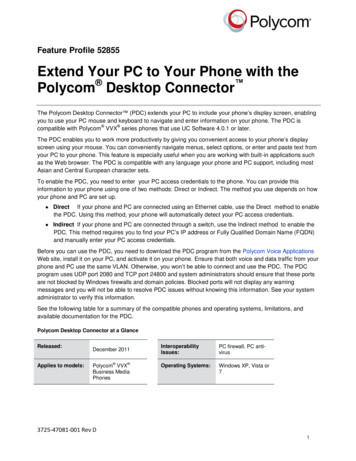
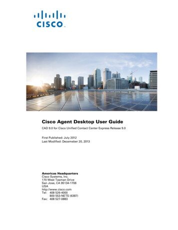
TS-user manual 10th ED v2.qxd12/16/20033:02 PMPage 4SERIALAttach the supplied serial cable (RS232) that connectsTalkSwitch to your PC. If you use the serial port youcannot use the USB port simultaneously.POWERPlug the supplied AC Power Adapter in here. Rating:16VAC 1.1 A output. Do not use any other power adapteras this may cause damage.By default, TalkSwitch is set to Serial connection. To activate USB connection, dial91from an extension then reset TalkSwitch. To return to Serial connection, dial90and reset TalkSwitch.The ‘PF’ box in between E4 and L1/L2 represents power failure support. In the eventof a power failure or loss of power to TalkSwitch, Extension 114 will be able to receivecalls and make calls on Line 1.1.3.2 The TalkSwitch 48LANE5E6E7E8E1E2E3E4L3/L4L4L1/L2L2MEMORY SLOTPFMUSIC4PAUSBSERIALPOWERJacks/PortsWhat to plug inMUSICPlug in a radio, CD player, PC soundcard or any otherdevice that emits an audio signal if you wish to useTalkSwitch's Music-on-Hold feature. This is a 1/8" (3.5mm) phono jack. Mono cables are recommended. If youhave multiple TalkSwitch units on a LAN, you will needto provide a music source to each TalkSwitch.PAConnect to a P.A. system if you wish to use the externalpaging feature. This is a 1/8" (3.5 mm) phono jack.Mono cables are recommended. If you have multipleTalkSwitch units on a LAN, you will need to provide aconnection from each TalkSwitch to the PA Amplifier.TalkSwitch User Manual
TS-user manual 10th ED v2.qxd12/16/20033:02 PMPage 5LAN PORTYou can connect to an Ethernet hub using a Category 5cable with RJ-45 connectors. This will supportconfiguration across the LAN. If you have 2 or moreTalkSwitch 48 units, you can ‘network’ them and theywill function as a single system. There are 3 LEDs nextto the LAN port. The top LED is on when a link has beenestablished with any TalkSwitch or PC runningTalkSwitch software. The 2nd LED is on when data isbeing received and the 3rd LED is on when data is beingtransmitted.E1 - E8Plug in any analog device that uses a standard (RJ-11)telephone jack, such as: telephones, fax machines,internal or external PC modems, etc. TalkSwitch identifies the extensions as 1x1 to 1x8. (x represents the unitID number assigned to that TalkSwitch unit). By defaultall TalkSwitch units are shipped with a unit ID 1. Thismeans the extensions are 111 to 118. If it had unit ID 2then they would be 121 to 128. For details on setting up2 or more units on a LAN to operate as ‘networked’units, please see section 1.5.L1/L2, L2, L3/L4, L4This is where you plug in your telephone lines (RJ-11).If you have 2 lines out of 1 phone jack, you can plug intothe 1/2 and 3/4 jacks. Use a surge protector if you livein an area prone to lightning strikes.USBUse the USB port if your PC supports USB connectivity. Ifyou use the USB port, you cannot use the serial portsimultaneously. Windows 2000/XP currently notsupported for USB connectivity.SERIALAttach the supplied serial cable (RS232) to connectTalkSwitch to your PC.MEMORY SLOTMemory expansion slot. Used to expand internalmemory for voicemail and Auto Attendant messages.TalkSwitch Memory cards can be purchased from yourlocal TalkSwitch reseller. Simply place the memory cardin the slot and TalkSwitch will automatically detect andstart using the extra memory within 20 seconds.POWERPlug the supplied AC Power Adapter in here. Rating:16VAC 1.1 A output. Do not use any other power adapteras this may cause damage.1.0Installing TalkSwitch5
TS-user manual 10th ED v2.qxd12/16/20033:02 PMPage 6By default, TalkSwitch is set to Serial connection. To activate USB connection, dial91from an extension then reset TalkSwitch. To return to Serial connection, dial90and reset TalkSwitch. No commands are required to use the LAN connection.The ‘PF’ box in between E4 and L1/L2 represents power failure support. In the event ofa power failure or loss of power to TalkSwitch, Extension 114 will be able to receive callsand make calls on Line 1.1.4Plugging into the Back Panel1.4.1 Attaching telephone lines to TalkSwitch line jacksYou can connect your telephone lines from the wall jack(s) to the TalkSwitch Linejacks with the phone cables provided. Take note of which telephone line is connectedto which Line Jack on TalkSwitch - this information will be used in the configurationsection. In order to minimize disruption to your business, you may want to configureTalkSwitch first before connecting it to your lines and phones.We recommend that you connect surge protectors between TalkSwitch and yourtelephone lines to protect against lightning damage.1.4.2 Attaching phones and other devices to TalkSwitch extensionjacksYou can connect any analog device (regular telephone, cordless phone, fax machine,answering machine, modem) to TalkSwitch's extension jacks. Multiple devices can beconnected to each extension jack by 'chaining' them together or using a line splitter.To Attach a Single Line Corded or Cordless Telephone, Fax Machine or AnsweringMachine:Connect your single line analog telephone or fax machine to one of TalkSwitch'sextension jacks (E1 to E4 for the TalkSwitch 24 and E1 to E8 for the TalkSwitch48) just as you would if you were plugging them into a standard telephone walljack.To Attach a Two-line Telephone:Option # 1 (Use it as one TalkSwitch extension.)Disregard the telephone's Line 2 jack (plug-in). Connect the telephone's Line 1plug-in to any one of TalkSwitch's extension jacks. You will still be able to accessboth telephone lines in the same manner as if you were using a single linetelephone attached to TalkSwitch.6TalkSwitch User Manual
TS-user manual 10th ED v2.qxd12/16/20033:02 PMPage 7Option # 2 (Use it as two TalkSwitch extensions.)You could use your two-line telephone as two separate TalkSwitch extensions.Connect the telephone's Line 1 and Line 2 plug-ins to two separate extensionjacks.Most two-line phones have separate plug-ins for two incoming telephone lines (Line 1and Line 2). If your two-line telephone does not have separate plug-ins, you can usea "Line 1/Line 2" line splitter to separate the two lines. Download the Quick Guide atwww.talkswitch.com for more detailed examples on connecting multi-line phones.To Attach an Internal or External Modem:Simply plug the modem's telephone cable into one of TalkSwitch's extensionjacks. Your modem is now a TalkSwitch extension and will be able to access alllines and take advantage of TalkSwitch's call routing features.If you would like to use a telephone on the same extension as your modem,simply plug the telephone's cable into the modem's telephone jack. (Mostmodems have a telephone jack, located beside the 'Line In' jack.)You do not have to attach a PC to TalkSwitch (via the Serial or USB ports) foryour modem to be functional.If you don’t want to change your dial up settings for the modem, you will needto enable Direct Line Access for the extension associated to the modem. Seesection 2.3.1.4 for more details on configuring Direct Line Access.1.4.3 Connecting Devices to the Music and PA JacksThe Music jack is designed to support any audio source (CD player, radio, tape player,sound card etc.) for playing music or messages to callers while on hold. Simplyconnect the audio source via its headphone output to the Music jack. The Music jackrequires a 1/8” (3.5mm) phono connector. If you have more than one TalkSwitchconnected to a LAN, you will need to provide audio to all the Music jacks on eachTalkSwitch.NetworkedThe PA jack can be connected to a PA System for external paging or to anamplification system to screen voicemail or to use as a line simulator. The PA jackrequires a 1/8” (3.5mm) phono connector. If you have more than one TalkSwitchconnected to a LAN, you will need to provide a connection from e
User Guide DESKTOP PHONE SYSTEM Software & Firmware Version 2.41 TS-user manual 10th ED v2.qxd 12/16/2003 3:02 PM Page i