Transcription
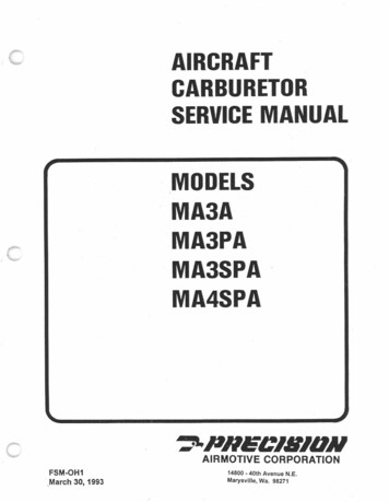
3SPAMA4SPAc PNECIIIIDNAIRMOTIVE CORPORATIONFSM-OH1,March 30, 1993-40th Avenue N.E.Marysville, Wa. 9827114800
JWARNINGWARRANTY AND LIABILITY INFORMATION: The useof parts NOT AUTHORIZED by Precision in alteration or modification of the carburetor and voidsall warranties.Precision Airmotive will accept nowarranty. or responsibility"iabilityfor carburetorscontaining UNAUTHORIZED parts.Any operatorand/or overhaul facility responsible for installation ofUNAUTHORIZED parts may have the sole and fullliability for property damage or injury, including death,'arising from any malfunction of the carburetor inwhich such parts are installed. This manual is notapplicable and should not be used for the installationof parts NOT AUTHORIZED by Precision Airmotive.* *Reference Precision Airmotive Service Bulletin MSA-5 andService Information Letter 10-21-92.:)Copyright @ 1993 Precision Airmotive Corporation, Everett, Washington 98204All rights reserved. Printed in the United States of America.
J()nIl/IONAIR MOTIVE CORPORATION PHE.nONAIR MOTIVE COR'uAATIONCARBURETOR PUMP DISCHARGE{;HECK VALVEACCELERATINGPUMP LEVERCARBURETOR PUMP DISCHARGEACCELERATINGPUMP LINKCHECK VALVE SPRINGCCARBURETORPUMP DISCHARGECHECK VALVE ASS'YHOLE 2-MEDIUMHOLE '-MINIMUMHOLE 3-MAX (NORMAL)THROTTLE SHAFTTHROTTLESTOP CREWIDLE NEEDLE SEATIDLE EMULSION CHANNELIDLE ADJUSTING NEEDLEIDLE AIR VENTTHROTTLE.cOVERFIG. CPUMP CHAMBERACCELERATINGPUMP PLUNGERPUMP INLET SCREENPUMP INLET CHECK VALVECARBURETORPUMP DISCHARGECHECK VALVE ASS'Y\THROTTLE FLYIDLE NEEDLE DELIVERYFIRST FLY HOLE DELIVERYSECOND FLY HOLE DELIVERYTHIRD FLY HOLE DELIVERYTHROTTLE FLY CLOSEDVENTURIMIXING CHAMBER & THR. BOREBODY & BOWLFLOAT VALVE & SEATLEVER RETAININGACCELERATINGNUTFUEL INLET SCREEN ASS'yMIXTURE CONTROL LEVERTHROTTLE STOPECONOMIZERCHANNELECONOMIZER HOLEATMOSPHERIC BOWL VENTNOZZLE AIR VENTNOZZLE OUTLETIDLE AIR VENTNOZZLE BORENOZZLENOZZLE WELLNOZZLE BLEED HOLESACCELERATING PUMP.DISCHARGE TUBEIDLE SUPPLY OPENINGIDLE FUEL ORIFICEIDLE TUBEPOWER JETFUEL CHANNELMIXTURE METERINGVALVE ASS'YMIXTURE METERING VALVEBOWL DRAIN PLUGFLOAT ASS'YMIXTURE METERING SLEEVEFIG, DMODELMA4SPA
E5THROTTLEBODY DISASSEMBLY5FUELBOWLDISASSEMBLY6CLEANINGAND INSPECTION7EXPLODEDVIEWOF CARBURETOR,."-8 AND OWLASSEMBLY16:INSTALLATIONOF WARNING LABELTEST TREATMENT17TORQUESPECIFICATIONS17c-3-
NOTEModels MA 3A, MA 3PA, MA 3SPA, and MA 4SPA are very similar and this overhaul section willapply to all.Model MA 3A does not have an accelerating pump circuit. (Example Part No. A10-3103-1 as usedon the Lycoming 0-235 C1) SPECIAL TOOLS na; II12- I3"rTjy I5I4"vI67910I13- wII11.8 0. -14Ai,.!.J12REFPARTNONO1M-72M-12NOMENCLATURENozzle wrench 1/2 inch (Snap-On No. SF-161)Socket extension3M-13Socket extension handle4M-83Venturi assembling tool5M-866M-104Throttle shaft bushing driverFloat valve seat remover7M-1088M-109Throttle shaft bushing reamerThrottle valve bolt clincher9M-120Venturi extractor10M-122Throttle shaft bushing remover11M-123Pump stem packing stake punch12M-123Pump stem packing stake pilot13M-133Torque tool for pump discharge tube.14M-134Locating tool for pump discharge tube15M-510Float clearance gage (Not shown, Ref. pg 14)-4--
FAILURE TO FOLLOW THESE INSTRUCTIONS MAYRESULT IN ADVERSE CARBURETORPERFORMANCE AND ENGINE OPERATION.STANDARD MA 3 & 4DISASSEMBLY PROCEDURE., -:/.5)Remove pump.linkcotter pins (9), pump link(10), and pump plunger assembly (11). Notehole location of pump link in pump lever (13).Remove accelerator pump lever screw (12),lever (13), and throttle opening spring (14).Remove pump packing washer (15) and pumppacking(16) with a. pointed tool or small screw.driver.Referto exploded view,pages 8 &9 forComplete Parts Reference Numbers1)Separate the throttle body and bowlbybending tab washers (1) and removing bowl. cover screws. (2) .Note: Old models may havesafety wire and cross hole drilled screws.Tap casting lightlywith a soft faced hammer2)to loosen and pull castings apart, beingcareful not to damage the float.THROTTLE BODY DISASSEMBLY3)6)7).9)Remove float shaft cotter pin (3), shaft (4),float (5), retraction clip (6), and float valve (7).Discard bowl gasket (8).4)Remove mixture control clamp screw (17),and safety washer (18).Remove mixture control lever (19), lock wireloop (20), spring (21), thrust washer (22), andpacking (23).Remove mixture control valve (24),horseshoe washer (25), and gasket (26).Remove float valve seat (27) and gasket (28)using tool M-104or a large screw driver. SeeFigure 1.Make note of throttle lever position beforeremoval. Remove throttle lever cotter pin(29), nut (30), and lever (31).Remove throttle valve screws (32), valve (33)8)10)11)12)HANDLE.C13)/and throttleshaft (34).14)'"'.5"Remove throttle adjusting screw (35), andspring (36).Remove idle adjusting needle (37), spring(38), and retainer (39). NOTE: some modelsdo not use retainer (39). Refer to appropriateparts list section for proper configuration.Venturi (43) seldom needs service, however if15)---./"').16)jFIGURE 1.necessary, press out the venturifromthethrottle valve sideusing tool ,M-120as showninFigure2.-I'.,FIGURE 2-5-
17)Remove throttle shaft bushings (44) using toolM-122 or any standard bushing removal tool.See Figures 3 and 4.18)Remove economizer jet (45) if used, ventscreen (42) if used, and idle drill plug (66) ifused. Note: Heating may ease removal ofRemovefuel inlet strainer assembly(46)andgasket (47). Remove float bracketscrews(63), and bracket (64).FUEL BOWL DISASSEMBLY19)20)Remove idle tube (48) and drain plug (49).21)Remove nozzle (50), safety washer (51), andnozzle gas,ket(52). See Figure 5.idle drill plug., If lead ball is used in place ofidle drill plug, DO NOT REMOVE.1Note: Occasionally the nozzle gasket will stayin the casting when nozzle is removed. Makesure it is removed.22)Remove pump discharge check valveassembly (53), safety washer (54), and gasket(55). NOTE: Do not disassemble the pumpdischarge valve (53)."23)Remove pump inlet retainer screws (56),safety washers (57), retainer flange (58),strainer housing (59), gasket (60), screen (61),and inlet check valve assembly (62). Pumpdischarge tube (Figure 5) seldom needsservice or removal. If it is damaged or loosepull it carefullY'out of its casting counter boreand discard.)THROTTLE SHAFT BUSHING REMOVERFIGURE 3NOZZLE WRENCHTHROTTLE SHAFT BUSHING REMOVER'-'")SOCKET EXTENSIONHANDLE./'''''\FIGURE 5 .IFIGURE 4
CLEANING AND INSPECTIONCInspectionCleaning ProcessUse a recommended carburetorcleaner andthe cleaner manufacturer'sprocedureto soak,,rinse,and blowout to assure completecJeaning. Onlymetal parts are to be placedincarburetor cleaner. Do not expose non metalparts to carburetorcleaner.Carburetorshave by design requirementsverysmall passages, channels, and orifices.These are quitedifficultto inspectusingthenaked eye. Usingequipmentsuch as anOtoscope or other magnifyingdevicewillenable you to see these difficultplaces.24)25)26)Seals and packingFloat valve and seat assemblyAccelerator pumpFloat shaftNOTE: Fuel inlet strainer assembly should bereplaced if the strainer screen is broken at anyplace or cannot be satisfactorily cleaned.27)WEAR LIMITS FORMA-' AND MA-4SPACARBURETORSINDEXNO.DESCRIPTION,Throttle shaft bushingsRetainersIMPORTANT: Do not clean passages incastil)gs or calibrated parts(nozzle, idle tube,etc.) with wire or small drills. Compressed air,carburetor cleaner, and a small, soft bristlebrush wQrkquite well.cThe followingparts should always be replacedduring carburetor overhaul:AllgasketsNormal aircraft quality inspection techniquescan determine reusabilityof carburetorcomponents. Abnormal wear, cracks, warping,or damage are, of course, just cause forrejection. Wear beyond the limitsshown inTABLE I is also just cause for rejection:PERMISSIBLE PERMISSIBLEWORN DIM.WORNCLEARANCET-BodyMixture control hol. In body22224Mixture control v,lv. lTon'".215225.007T-BodyAc"",I,,,torT-bodypump hol. In.00824Mixture control v,lv. (Bottom).2480Mixture control sleev.Ro't shaft brack.t.2500.100.002Bowl64.00644Roatsh,ftRoat shaft5Roallever niyot.092.092.008T-BodyThrottle shaft bushing holesNOTE: Latemodel aircraftare all equippedwithsoft engine mounts. Thishas created amore severe vibrationenvironment,causingdifferentwear characteristicsin differentaircraft. Careful inspection is required.100.3775.002Throttle shaft bushinn 0.0.Throttle shaft bushing 1.0.3750.3135.0053413Throttle shaftAccel",torpump lever holes105Accel",tornump link.3085.132.008cSowlT-Body.122Roat adjustment tabwoarspotAccelerator pumo cylinder .100dia.630wearspotThrottle stop pad onT-body-- .010 deepTABLE I-7-
J"'PNECJBJDN-,J,tAIRMOTIVE CORPORATION ( "@ "I////@?IIII11.@II!@I"- "',,).J,Ii'@@Iii@ @&,I@iI@0 I,iNOTE: This illustration does notdepict a specific carburetor butis acomposite view. All componentsare shown but not always in theexact position."'".Ift
(0 ", , ,::, ./ry."',';J, -,T "' "'j;t " ; ,/,L :FF:; -'/ ;,,: ".;?/fi,;", J ,'., .'-"- : - ,'" .,illALVE233-615 FLOAT Vh--'-,;I30-766 FLOAT.n\II (1);":":- - !.-J1jQj-()@)i'- ."@),'. I-IEJI Qi)", ,JtoI/.---Il -/-;/)II//I@ !-----I----------I '"IV/ . /)t9J@@"' "1'"I.fRI\It f - @/§iJ'C-9-@
MODEL MA 3 & 4 ASSEMBLY PROCEDURE30)THROTTLE BODY28)Install pump stem packing (16) and retainer(15) using tools M-123 and M-123A. PlaceLightly coat the bushing with Loctite RC-680tool M-123A packing pilot in place on theper Loctite's recommended instructions.bottomside of throttle body;slip packing(t 6)Install throttle shaft bushings using tool M-86In the cavity on top side. Place retainer (15)bushing driver. Place bushing (44) on driverover packing and stake in place with tool M-and tap into place. repeat on opposite side.123. Remove pilot.Install venturi (43) using tool M-83. Place the. See Figure 6.Cure in locationfrom two to.four hours. Heat not to exceed 11OaF may be31) .venturi in position so that the notch in the sideof the venturi will be in alignment with theused to speed curing.nozzle and the legs engaged in the grooves inthe throttle bore.').//.FIGURE 6. THROTTLE SHAFT BUSHING TAP WRENCHREAMER/)ANOTE: Repeated rebushing of older mod.elswith the old style steel bushings may haveenlarged the bore with resultant loss of pressfit. Make sure in this case that the looseFIGURE 7bushings are in location.29)Line ream the bushings with tool No. M-108.See Figure 7.-10-
Install the economizer jet (45) if used.32)c41)Exercise caution, so as not to damage or burrthis jet since this can cause a change in flow.'Install vent screen (42) if used.33)34).Install idle drill plug (66) to 12-16 inch poundswith Loctite 222 or equivalent mild threadlock.42)Install throttle shaft (34), throttle valve (33),and throttle valve screws (32). Run screwslightly into place, rotate the shaft to the closedposition and tap the valve lightly with thescrew driver blade to seat the valve in throttle35)spring end through the cross hole drilled screw(12) to safety and bend the end ofthe springtighten t e.screws. Torque screw (32) to 10-15inch pounds.closed to wide open. Note: Certainover to secure. If model does no incorporatespring use.safety wire to safety screw (12).Place throttle lever (31) at proper anglelocation on throttle shaft and secure withretaining nut (30). Torque nut (30) to 20-60 .inch pounds. Install cotter pin and bend.carburetors do not use a wide open valve andNOTE: Carburetor without the throttle leverSafety the throttlevalve screws in place withinsta,lIed, the shaft will rotate freely from fullyyou may notice that thevalve is limited up to150 from the fully open position. This isnormal and an important part of the fullsafety wired as shown in Figure 9.43)44).Insert the pump (11) carefully through thepacking and install pump link (10) and cotterInstall throttle ,adjusting screw (35), and spring(36).37)locknut retaining feature on the end of thethrottle shaft must have the throttle leverthrottle requirements.DO NOT CHANGE.36)(63) should be replaced if nylon long-Iocismissing or ineffective.Slide throttle opening spOng(14) (if used)over the end of shaft.(34) and insert the endthrough the hole in casting web. Installaccelerating pump lever (13) and secure inplace with screw (12). Torquescrew (12) to 811 inch pounds. Insert the throttle openingbore. Hold the throttle valve closed andclinching tool M-109. See Figure 8. CarefullycInstallfloat bracket (64) withscrews(63)torque to 8-11 inch pounds. NOTE:Screwpins (9).Note: The accelerating pump lever has threeInstall retainer (39), spring (38), and idleholes into which the upper end of the pumpneedle (37). Approximate setting 1-1/2 to 2turns from seat. NOTE: Some models do notconnecting rod can be installed.use retainer(39). Refer to appropriate partslistsection for properconfiguration.38)Place horseshoe washer (25) in its groove onmixture control )lalve (24). 'Place washer (26)over valve head and insert into casting fromthe39)THROTTLE VALVEBOLT CLINCHERbottom.Slide packing (23), washer (22), and spring(21) over valve head. Place tip of the lockwire loop (20) into its hole in valve head. Alignlever (19) with wire loop and push down tocompress spring (21). Assurethat the loopof./the lock wire is toward the valve.0Install clamp screw (17) through safety washer40)(18), lever (19) and lock wire (20) and bendsafety tab washer to secure. Torque screw to20-28 inch pounds,FIGURE 8
\FIGURE9The outer hole, known as the No.3 hole, isapproximately midway in height between theupper and lower holes. The NO.3 holeprovides the longest stroke for delivery ofmaximum amount of accelerating fuel. Thelower hole is known as the NO.1 hole and45)against the top spring seat (12) to compressthe spring (13) far enough to permit insertion f the spring seat locating pin (10). After thepin (10) is in place, release pressure on thespring (13) to hold the pin securely in position.Press down against the top of the pumpplunger rod assembly (11) to make certainthat the stem on the pump plunger and stemassembly (16) willslide freely in the end of theproduces the shortest stroke. The middlehole, or NO.2 hole, produces a mediumsupply"of accelerating fuel. Refer to FIG C,Page 2,Note: Some models have a pump plungerassembly which inCorporates a collapsingfeature to prolong the pump stroke.Assemble this type in accordance with thisspecial section and Figure 10.a. Hold a spring seat (12) against each end ofthe spring (13) and slide the pump plungerand stem assembly. (16) through the spring.b. Slide the pump plunger rod (11) over theend of the pump plunger stem (11) so that thehole at the lower end willbe in alignment withthe slot in the stem. Apply finger pressure46)47)--0---8-1tI;-IlI nl--J!1',I48)49)50)51)I stem.Ifthe pump leather expanding spring (17) wasfIQremoved, install it carefully under the pumpleather.Install fuel inlet fitting-strainer assembly (46),and gasket (47). Torque fitting (46) to 10-12foot pounds:Install noat valve seat (27), and gasket (28)using tool No. M-104. See Figure 11. Torqueto 10-12 foot pounds.CAUTION: Exercise care during the followingoperationsto preventdamageto the noat.SOCKET EXTENSIONHANDLE\.11 ---::t:; I e13'iI:II IIONL. "-0"2 1'0 17 -18I ::[16t-----FIGURE 10FIGURE 11-12-"
(!,FIGURE 1252)53)54)(c55)FIGURE 1356)To install the float, place the throttle body withthe mounting flange down and install theproper throttle body to bowl gasket (8).Place the float valve retractor clip (6) on thefloat valve IJ) as illustrated in Figure 12.Place the float valve and retractor clip on thefloat (5) as illustrated in Figure 13.Make sure the float valve is centered on the57)adjustment tab on the float. The float valveretractor clip should not hold the float valvetight against the float lever but haveapproximately .005" clearance when viewedas in Figure 13.Place the float, valve, and clip assembly intothe float bracket (64) with the valve (7) in thefloatvalve seat (27)(Reference Figure15).58)Insertthe float lever shaft (4)throughthe floatbracket and floatlever hinge and safety inplace withcotter pin (3). Bend the ends of thepin allthe way back.CAUTION:Insurethat the floatshaft is free torotate and that the floatand valve movementis not restrictedbetweenthe fullyopen andfullyclosed positionof the floatvalve. This isapproximately1I2-inchof floattravelmeasured at outer end of float. The floatsetting is established as shownin Figure14with7/32"clearance betweenthe floatandgasket measured near the outer end of eachfloat.Ifadjustment is required,bend the floatleveradjustmenttab, locatedover the floatvalve,. to achieve thel/32" setting. A smallscrewdriverbent 30 degrees approximately1/4-inchfromitstip is a usefultoolforsettingthe float. - :. I:' . 'Q! -7;""- r /'.I.29-19' CL "0BAFFLEFIGURE 14.''i''\233.615FLOATVq'\\ALVE"-"'30-766 flOAT"\,IFIGURE 15-13-
r59):, 60)61)66)CAUTION: Both float pontoons must be at thesame height above the gasket.CAUTION: DO NOT APPLY PRESSURE TOinlet screen (61): gasket (60), housing(59),and flange (58) (chamfered side towardTHE VALVE AND SEAT DURINGcasting), and secure with screws (56) andADJUSTMENT BENDING.safety washers (57). Bend tabs to seCure.Use tool No. M-510 as a clearance gauge to . .- Torque check valve assembly (62) to 8-12inch pounds and screws (56) to 14-18 inchcheck float before assembly in accordancepounds.with Figure 16. The float may be repositionedlaterally by loosening the float bracket screws62)Install pump inlet check valve assembly (62),67)Install drain plug (49) with a small amount of(63), moving the bracket slightly, andthread lube. Torque drain plug (49) to 25-30retightening screws. Set throttle body aside ininch pounds. (CAUTION-Make sure no threada clean area while completing bowl assembly.lube can be put in ahead of the plug).CAUTION:To prevent possible damage to the68)float do not blow on or into the carburetorPlace power jet gasket (52) on shoulder ofpower jet in the base of nozzle and insertassembly with compressed air. Failure tonozzle through gasket safety washer (51), andfollow these instructions may result in adverseinstall nozzle firmly into the bowl casting. Seecaiburetor performance and engine operation.Figure 17. NOTE: It is best to install nozzlewith bowl inverted to insure that the powerjetFUEL BOWL ASSEMBLYgasket does not fall into well and block power63)jet.Install idle tube (48) in casting exercising carenot to damage the tube. Torque idle tube (48)to 3-5 inch pounds.64)65)Install pump discharge check valve assembly69)Bend ALL tabs in washer (51) to secure.70)The pump discharge tube seldom needs(53), gasket (55), and safety washer (54).service. . However, if it needs to be replaced, iti1i\is installed with Loctite mounting compound V/JITorque valve assembly (53) to 50-70 inchand cured in place, in accordance with thepounds. Bend tabs to safety.following instructions:.,fNOTE: Do not disassemble the pumpdischarge valve (53). It is faclory preset. If ithasbeen disassembled, it must be replaced.YOU ARE LOOKING INTO THE BOTTO" OF THE ".,,,IN PLACE ON THET ROTILE BOOY.".NOZZLE WRENCHGAUGEI ""'.1\ /"'"'"., GAGE ONM.". GAGE ON"' 5AND "'"SEROESJ ANDMA SEROESWlTH.520ROlLROOWITH"" DRILLROOCHECKCO"PLETE AROUNOBOTH PLOATSECTIONS'1//"'-. , SOCKET EXTENSIONHANDLEFIGURE1THEDRILLROD ,GAGEl SHOULD PASS FREEL'AROUNDBOTH FLOAT SECTIONSrFIGURE 16-14-
.PROCEDURE TO ASSEMBLE ACCELERATORDISCHARGE TUBE IN MA3 AND MA4 BOWLSQT)74).ilength of the end of the accelerator dischargetube which is inserted into the bowldischargeport. Thoroughly clean both surfaces withLoctite safety solvent. Clean surfaces insureconsistent bonding results. After applyingsafety solvent to accelerator discharge port incasting, swab with CLEANpipe cleaner toremove residual contamination. Afterapplying safety solvent to acceleratordischarge tube, wipe with a CLEANtissue toremove residual contamination. DO NOTBLOW WITH COMPRESSED AIR AFTERAPPLYINGSAFETY SOLVENT-moisture and72)c73)template M-134in place, assembledischarge tube irito discharge port with arotating motion to spread retaining compound.Parts may be repositioned up to one minuteafter assembly. After inserting pumpdischarge tube in place. place locating tubepart oftool. M-134 thru the hole as indicatedand down over the pump discharge tube andallow to cure in place. See Figure 18. IfPrimer T is used parts must be joined withinfour minutes after RC-680 is applied. IfPrimer N is used, parts must be joined withinten minutes after RC-680 is applied.Clean and roughen longitudinally (not radially)with#320 emery clothapproximately1/2 inchWith75)Allowto cure at roomtemperature. WithPrimer T foouring occurs withinfive minuteswith full cure in six hours. With Primer Nfixturing occurs in 15-30 minutes and full curein 12 hours.oil in the air may recontaminate the surfaces.Apply Locquic Primer Tor PrimerN to bothsurfaces. Allowprimerto visibly dry (2-5minutes) before applying retaining compound.Apply primer to accelerator discharge port incasting with a pipe cleaner wetted (notsaturated) with primer. Apply primer todischarge tube by wiping.Apply Loctite Retaining Compound RC-680 tothe accelerator pump discharge tube brushingor wiping on approximately one-half inchlength of the tube end which is inserted intothe accelerator discharge port approximately1/16 inch from the end oftube. DO NOT76)-After full cure the Loctitejoint must be ableto withstand48 inch ounces of torque appliedat the rotational axis of the discharge tubeentering the discharge port without movementof the discharge tube. See Figure#19.ALLOW RC-680 TO ENTER TUBE.TOOL #M-134LOCATING TUBE IN PLACE OVERPUMP DJSCHARGE TUBEUSING M-133 TOOL ON 3/8 SOCKETAPPLY 48 INCH OUNCES TOROUEf(FIGURE 1GFIGURE 18-15-
THROTTLE BODY AND BOWL ASSEMBLYC. Allow the fuel pressure at 0.4 psi to remain77)Carefully assemble the castings together byfor a period of at least 15 minutes and theninserting the pump plunger into its cavity inraise the fuel pressure to 6.0 psi. (There wilt""\.be a slight rise in fuel level as the pressure i the bowl (extreme care should be exercised tocarefully guide the mixture metering valveincreased.) Allow the 6.0 psi pressure toremain for at least five minutes after the fuel(24) into its seat in bowl. Assure that thelevel has stabilized.keep from damaging the pump leather),l,accelerator pump discharge tube is locatedbowl cover screws (2) and safety washers (1)D. If the fuel rises to the level of the partingsurface of the castings or runs out of theand torque in place 35-45 inch pounds. Bendnozzle, the bowl and throttle body must beup a minimum of two tabs on all safetywashers.separated and the float valve andseatinside the center ring of the venturi. Installcleaned or replaced. CAUTION: Under nocircumstances change the float level from theINSTALLATION OF WARNING LABEL78)established setting to correct flooding or tochange fuel level.Clean the side of the carburetor body usingacetone or equivalent degreasing solvent.Allow the surface to dry completely. RemoveE. With fuel supplied to the carburetor asthe peel"off backing from the waming label(65) and attach the label to the carburetorbody.shown in Figure 20, operate the throttle leverfor several strokes to fill the acceleratingpump and passages. Then close the throttle,open it fully again, and hold it for a fewTEST PROCEDUREseconds. If the accelerating pump isGENERAL79)0After the carburetors have been overhauledoperating correctly, a solid stream of fuel will.be discharged from the accelerating pumpand the checks performed as specifieddischarge tube or jet and will gradually diethroughout the overhaul procedures, theaway after the spring on the pump plungerreaches its limit.carburetors should be equal to new units.Final adjustments should be made at the time!WARNING: DO NOT STAND DIRECTLYthe carburetor is installed on the engine.OVER THE CARBURETOR FLANGE ASFLOAT VALVE AND SEAT TESTFUEL WILL BE DIRECTED INTO THE FACEOF THE OPERATOR.(See Figure 20)80)A. Connect the inlet fitting of the carburetor toa fuel pressure supply of 0.4 psi.B. Remove the bowl drain plug and connect afitting, rubber hose, and glass tube to thePARTINOSURFACEcarburetor drain connection. The glass tubingshould be positioned vertically beside thecarburetor.IIRUBBER-16-HOSE1
I,F- If the fuel discharge from the dischargetube is weak, or if air is dispelled, it is an'"0Iindication that the pump plunger, pump,discharge or inlet check valve are notfunctioning properly. Disassemble thecarburetor and mak'!necessary repairs,G. Remove the sight tube fixture and allowthe fuel to drain out. Operate the pump toclear the fuel out of the pump cylinder andpassages. Reinstall and safety drain plug.PRESERVATIVE TREATMENT81)If the carburetor is to be placed in storageafter overhaul, the bowl drain plug should beremoved and the carburetor flushed internallywith soluble corrosion preventive oil, MilitarySpecification MIL-C-4339. After draining thesurplus oil from the carburetor, enough willcling to the parts to provide internal protectionduring storage. Replace the bowl drain plug.ICTORQUE SETTINGS FOR MA-3 AND MA-4SPA CARBURETORS-Screw Throttle valveScrew - Mixture control leverScrew - Throttle lever clamnScrew - Pumn inlet strainer housinoScrew- Float bracket-'C'Screw Idle drill nluoScrew - Pumn leverninScrew - Throttle bodv to bowlValve assV:- Pumn inletValve assv. - Pumo dischameNozzleNut - Throttle leverFuel inlet and strainer assv.Pluo - Bowl drainIdle tubeFloat valve seat10 -15 in-Ibs15 - 20 in'lbs20 - 28 in-Ibs14 - 18 in-Ibs8 -11 in'lbs12 -16 in'lbs Thread lock8 - 11 in'lbs35 45 in-Ibs8 - 12 in-Ibs50 - 70 in-Ibs45 - 60 in-Ibs20 - 60 in-Ibs10 - 12 ft-Ibs25 30 in'lbs3 - 5 in'lbs10 - 12 ft'lbs.--'TABLE II.O(!.7
.1'.JI PNECJIIJDNAIRMOTIVECORPORATION.14800 40th Avenue N.E.Marysville, Wa. 98271Tel: (360) 651-8282 Fax: (360) 651-8080-"'"i
c c c aircraft carburetor service manual models ma3a ma3pa ma3spa-ma4spa pneciiiidn airmotive corporation fsm-oh1,march 30, 1993 14800-40th avenue n.e. marysville, wa. 98271