Transcription
Scissor-Jack-Damper Energy DissipationSystemAni N. Şigaher,a) M.EERI, and Michael C. Constantinou,b) M.EERIInstallation of damping devices has been limited to diagonal or chevronbrace configurations until the recent development of the toggle-brace configurations. These configurations magnify the effect of damping devices, thusfacilitating their use in stiff framing systems. This paper introduces thescissor-jack-damper system that was developed as a variant of the togglebrace-damper systems, with the added advantage of compactness. The effectiveness of the scissor-jack configuration is demonstrated through testing of alarge-scale steel-framed model structure on an earthquake simulator. Experiments showed that despite the small size of the damping device considered,the scissor-jack system provided a significant amount of damping and substantially reduced the seismic response of the tested structure. Response history and simplified analyses produce results that are consistent with the experimental results. [DOI: 10.1193/1.1540999]INTRODUCTIONThe use of supplemental or damping devices to dissipate seismic energy in buildingand bridge structures has gained increasing interest in the past decade. These devices,commonly known as ‘dampers,’ exhibit either hysteretic behavior (e.g., yielding of metals, sliding friction) or viscoelastic/viscous behavior (e.g., fluid viscous dampers, solidand fluid viscoelastic dampers). The underlying objective of implementing energy dissipation devices in structural systems is to limit or eliminate damage to the structuralframe by dissipating most of the earthquake-induced energy which would otherwise beabsorbed by the load-bearing-system through inelastic deformations. Viscoelastic andviscous energy dissipation systems are also eminently suitable for wind vibration reduction. The interested reader is referred to the following for a review of this technology:Applied Technology Council (ATC) (1997), Soong and Dargush (1997), Constantinouet al. (1998), and Hanson and Soong (2001).Today, many countries utilize various types of damping devices as protective systemsto reduce wind and earthquake-induced vibrations in new and retrofit construction. InJapan, the majority of the applications utilize yielding steel devices and viscoelastic fluidor solid devices. In the United States, engineers have primarily used fluid viscous devices. In these applications, damping devices have either been installed in-line with diagonal bracing or as horizontal elements atop chevron bracing. The popularity of thesea)Graduate Research Assistant, Department of Civil, Structural and Environmental Engineering, University atBuffalo, State University of New York, Buffalo, NY 14260b)Professor and Chair, Department of Civil, Structural and Environmental Engineering, University at Buffalo,State University of New York, Buffalo, NY 14260133Earthquake Spectra, Volume 19, No. 1, pages 133–158, February 2003; 2003, Earthquake Engineering Research Institute
134A. N. ŞIGAHER AND M. C. CONSTANTINOUconfigurations is based on the engineers’ familiarity with such bracing systems and thefact that all experimental research studies have utilized only these two configurations forenergy dissipation systems.Exception to the rule of use of diagonal or chevron bracing configurations for damping systems has been the recent construction of two 37-story and one 38-story buildingsin the United States utilizing the toggle-brace configuration. As the name implies, thisconfiguration is based on the toggle mechanism, which magnifies the damper displacement for a given interstory drift. This amplification results in a reduction in the requireddamping force, and reduction in the damper volume, which may lead to reduction ofdamper cost. The damper force output is magnified through the same mechanism anddelivered to the framing system. The toggle-brace configuration is suitable for applications of wind response reduction and of seismic hazard mitigation of stiff structures. Atheoretical treatment of the system’s behavior, along with experimental results confirming the validity of the concept and the developed theory, and a brief description of applications can be found in Constantinou et al. (2001).An additional consideration related to the application of energy dissipation systemsis that in many cases the energy dissipation assemblies occupy entire bays in frames andoften violate architectural requirements such as open space and unobstructed view. Withthis intent, the scissor-jack-damper system was developed as a variant of the togglebrace-damper system. The system combines the displacement magnification feature withsmall size, which is achieved through compactness and near-vertical installation.This paper presents the concept underlying the scissor-jack-damper configurationand verifies the theory via experimental results. The experimental study includes earthquake simulator testing of a half-scale steel model structure equipped with fluid viscousdampers. Parts of the work described in this paper have been previously presented orbriefly described by the authors and coworkers (Whittaker and Constantinou 1999a,1999b, 2000; Constantinou et al. 2000; Constantinou 2000; Constantinou and Şigaher2000). The scissor-jack system is also briefly described in the recent EERI monographof Hanson and Soong (2001). However, this paper represents the first detailed treatmentof the scissor-jack-damper system and the related experimental results, which representpart of the doctoral dissertation of the first author.SCISSOR-JACK-DAMPER THEORYThe scissor-jack-damper system is best explained by first reviewing the conventionaldiagonal and chevron brace configurations, in which the displacement of the energy dissipation devices is either less than (case of diagonal brace) or equal to (case of chevronbrace) the drift of the story at which the devices are installed. If u and uD denote theinterstory drift and the damper relative displacement, respectively, thenuD f u(1)where f magnification factor. For the chevron brace configuration, f 1.0; for the diagonal configuration f cos , where angle of inclination of the damper with respectto the horizontal axis. The force FD along the damper axis is similarly related to F, thehorizontal component of the damper force exerted on the frame, through
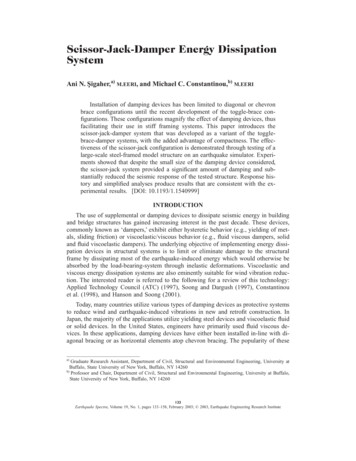
SCISSOR-JACK-DAMPER ENERGY DISSIPATION SYSTEM135Figure 1. Illustration of diagonal, chevron brace, scissor-jack-damper, and toggle-brace-damperconfigurations, magnification factors, and damping ratios of a single-story structure with linearfluid viscous devices.F f FD(2)Figure 1 illustrates a single-story structure with diagonal and chevron brace configurations. Also shown in the figure are the force, F, and the interstory drift, u. Considerthat this single-story structure has an effective weight, W, and a fundamental period under elastic conditions, T, and that it is equipped with a linear fluid viscous damper forwhichFD Co u̇D(3)
136A. N. ŞIGAHER AND M. C. CONSTANTINOUwhere Co damping coefficient, and u̇D relative velocity between the ends of thedamper along its axis. The damping force F, exerted on the frame by the damper assembly is given byF Co f 2 u̇(4)in which u̇ interstory velocity. It follows that the damping ratio of a single-story framewith a linear fluid viscous device can be written as Co f 2 g T4 W(5)It is essential to realize the effect of the magnification factor on the damping ratio.As Equation 5 suggests, the damping ratio varies proportionally with the square of themagnification factor. In the two conventional configurations in Figure 1, a damper designed to provide a damping ratio of 5 percent of critical when installed horizontally(chevron brace), will provide a damping ratio of 3.2 percent of critical in the diagonalconfiguration.In contrast to the familiar diagonal and chevron brace configurations, the scissor-jackconfiguration can achieve magnification factors substantially greater than unity. This isalso true for the toggle-brace-damper systems. Figure 1 also illustrates the scissor-jackdamper and toggle-brace-damper systems as implemented in a single-story frame. Thesesystems make use of shallow trusses that amplify the effect of the interstory drift on thedamper displacement and also amplify the small damper force and deliver it to the structural frame. The expression for the magnification factor, f, under the assumption ofsmall rotations, and its value for a typical geometry are also given in Figure 1. A substantial increase in the damping ratio with respect to that provided by conventionaldamper configurations demonstrates the efficacy of these systems.The presence of the magnifying mechanism in the scissor-jack system extends theutility of fluid viscous devices to cases of small interstory drifts and velocities, which aretypical of stiff structural systems under seismic excitation and structures subjected towind load. Fluid viscous devices require special detailing when operating at smallstroke. This results in an increased volume of the device and, accordingly, cost. In addition, in stiff structural systems, the required damping forces are large, leading to a further increase in the cost of the energy dissipation system. These damper configurations,therefore, may lead to cost savings, provided that the cost of the support framing is notsubstantially greater than the cost of the framing that would be required to support thedampers in conventional configurations. Moreover, the scissor-jack system may be configured to allow for open space, minimal obstruction of view and slender configuration,features that are often desired by architects.The scissor-jack damping system may be installed in a variety of configurations asshown in Figure 2.
SCISSOR-JACK-DAMPER ENERGY DISSIPATION SYSTEM137Figure 2. Possible installation configurations of a scissor-jack-damping system.MAGNIFICATION FACTOR AND FORCES IN SCISSOR-JACK SYSTEMThe effectiveness of the scissor-jack configuration is based on the magnification factor, f, defined as the ratio of damper displacement, uD , to the interstory drift, u. Figure3 presents an analysis of the movement of a single-story frame with a scissor-jack system. The magnification factor isf uD 兩A B AB兩 uu(6)where AB and A B denote the initial and the deformed lengths of the damper, respectively.It should be noted that the deformed configuration of Figure 3 does not take intoaccount any deformations in the frame (only rigid body motion is considered) and anyreduction in height due to column rotation. The latter has negligible effect on the magnification factor for typical values of interstory drift and for low-rise structures. Theframe deformations, on the other hand, may have notable effect on the magnification factor. As an example, consider that the beam in Figure 3 is simply connected to the columnon the left and rigidly connected to the column on the right. Upon an interstory drift
138A. N. ŞIGAHER AND M. C. CONSTANTINOUFigure 3. Analysis of scissor-jack movement and analysis of forces.towards the right, the beam will deflect upwards, causing a decrease in the damper deformation and thus, in the magnification factor. The opposite will occur when the beamto-column connections are reversed. This type of amplification/deamplification of themagnification factor will depend on the relative stiffnesses of the beam and the column,and the position of the point of connection of the scissor-jack on the beam. Additionally,the displacements due to the forces in the damper and in the scissor-braces (i.e., displacements due to finite stiffness of the scissor-braces) will reduce the magnificationfactor, regardless of the structural system configuration. A treatment of the effect of thedeformations in the frame and in the damper assembly, on the behavior of the frame willbe presented in sections that follow.Based on rigid body kinematics, the damper displacement may be expressed asuD 兩A B AB兩 2 ᐉ1 关sin共 兲 sin 兴(7)where angle of rotation of the scissor-braces. Preservation of lengths betweenpoints C and D requires that
SCISSOR-JACK-DAMPER ENERGY DISSIPATION SYSTEM139Figure 4. Dependency of the magnification factor on the scissor-jack geometry.2 ᐉ1 cos共 兲 2 ᐉ1 cos u cos (8)Utilizing Equations 7 and 8, the damper displacement can be written as冋 冉 再冎冊 册cos u sin 2 ᐉ1uD 2 ᐉ1 sin cos 1 cos (9)where in Equations 7 to 9, positive signs hold for drift towards the right (u and asshown in Figure 3) and for damper extension (uD 0). For drift towards the left, theseequations are valid with negative signs.Equation 9 may be used to calculate the damper displacement given a value of drift,provided the latter is small. However, the equation cannot be solved for the ratio of twodisplacements, which is of much practical value. Realizing that for most applications is very small, Equations 7 and 8 may be significantly simplified to easily yield the magnification factorf cos tan (10)It can be shown that Equations 1 and 10 provide a very good approximation to the exactdamper deformation (Equation 9) for 0.2 . Moreover, Equation 10 provides insightinto the major factors affecting the performance of the scissor-jack configuration.The dependence of the magnification factor, f, on angles and is illustrated inFigure 4. As the figure suggests, the magnification factor assumes very large values as approaches 0 ; but this has no meaning since the scissors tend to act as a single braceinclined at angle . Rather, when designing such systems, emphasis should be placed onthe fact that the magnification factor should have minimal sensitivity to small changes
140A. N. ŞIGAHER AND M. C. CONSTANTINOUin geometry. A typical geometry is shown in Figures 1 and 4, which is representative ofthe tested scissor-jack-damper system. Practical values of the magnification factor lie inthe range 2 to 5.The forces that act on the scissor-jack
The presence of the magnifying mechanism in the scissor-jack system extends the utility of fluid viscous devices to cases of small interstory drifts and velocities, which are typical of stiff structural systems under seismic excitation and structures subjected to wind load. Fluid viscous devices require special detailing when operating at small stroke. This results in an increased volume of the device and, accordingly,