Transcription
Int. J. Mech. Eng. & Rob. Res. 2015Manoj R Patil and S D Kachave, 2015ISSN 2278 – 0149 www.ijmerr.comVol. 4, No. 1, January 2015 2015 IJMERR. All Rights ReservedResearch PaperDESIGN AND ANALYSIS OF SCISSOR JACKManoj R Patil1* and S D Kachave1*Corresponding Author: Manoj R Patil, monarchmanoj37@gmail.comEvery engineering product involve cost effective manufacturing and its versatility in applicationmaintaining its aesthetics as well as assign service life without failure keeping those parametersin mind we focused our intention on designing and analyzing the jack model for actual serviceloads for varying models of automobile L.M.V. sectors. Automobile sectors are very keen at theirproductivity and customer satisfaction. We also keen at reducing the weight of scissor jack atthe same time maintaining its strength and service life. We made certain change in manufacturingprocess thereby made a new versatile jack that can be used for varying models of L.M.Vautomobile sector. Also the new design that made by Pro-e software can be tested by ANSYSsoftware.Keywords: L.M.V., Light motor vehicle, FEA, Finite element analysis, CAD, Pro-Eproduction system it is necessary to redesignthe various products for reducing the cost ofthe product over the same product. So we havechosen such exercise with the scissor jack.The main benefit of this paper is to reduce theunnecessary cost, reduce the over design, thedesign will be up to the mark. This paper willgive new approach to product design. Suchas in case of large volume, the cost reductionis more and it will increase the demand ofproduct in market itself. In case of themanufacturing of the scissor jack we canreduce the material of the product byconverting the manufacturing process, e.g.,Casting into sheet metal, in which the strengthINTRODUCTIONSince traditional jack that available in marketinvolve plenty of variety like screw jack. Wehad selected the traditional scissor jack forL.M.V. and focuses our intention to removeperm ant welds as that is the area wherechances of failure is more. We replaced weldjoints by rivets as well reduced materials byredesigning special brackets and employingspecial manufacturing processes fortraditional.As per the today’s scenario of costreduction, we need to find the cost effectivesolution for long term benefits. So in the1Department of Mechanical Engineering, SSVPS BSD COE, Dhule, Maharashtra, India.327
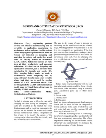
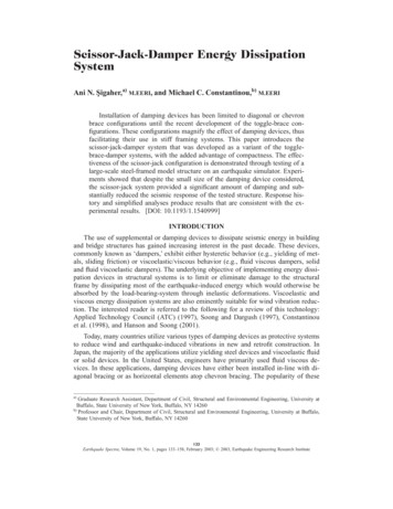
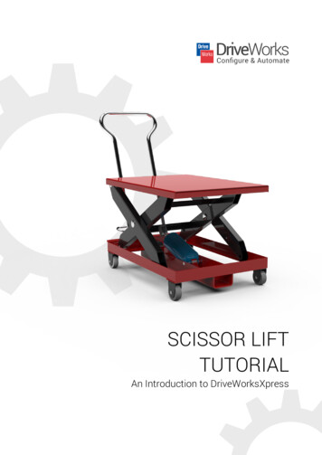
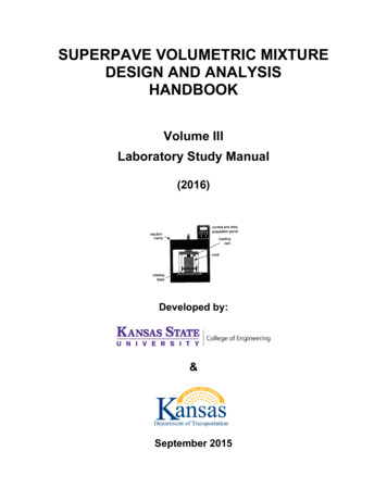
Int. J. Mech. Eng. & Rob. Res. 2015Manoj R Patil and S D Kachave, 2015of the product remain as it is and the cost ofthe material will be automatically reduces.Even part reduction by assembly process andno welding joints will give less deflection andthe large accuracy.runs across this assembly and through thecorners. As the screw thread is turned, the jackarms travel across it and collapse or cometogether, forming a straight line when closed.Then, moving back the other way, they raiseand come together. When opened, the fourmetal arms contract together, coming togetherat the middle, raising the jack. When closed,the arms spread back apart and the jack closesor flattens out again.OBJECTIVEThis paper includes the scissor jack ofautomobile L.M.V. vehicle. The objective of thisexercise will be1. To reduce the weight of the jack by changingthe manufacturability.Design and LiftA scissor jack uses a simple theory of gearsto get its power. As the screw section is turned,two ends of the jack move closer together.Because the gears of the screw are pushingup the arms, the amount of force being appliedis multiplied. It takes a very small amount offorce to turn the crank handle, yet that actioncauses the brace arms to slide across andtogether. As this happens the arms extendupward. The car’s gravitational weight is notenough to prevent the jack from opening or tostop the screw from turning, since it is notapplying force directly to it. If you were to putpressure directly on the crank, or lean yourweight against the crank, the person would notbe able to turn it, even though your weight is asmall percentage of the car’s.2. To reduce the no. of parts for simplifying theassembly process.3. Remove welding to avoid distortion.4. Product should withstand the currentstrength requirements.MATERIALS AND METHODSOperationA scissor jack is operated simply by turning asmall crank that is inserted into one end of thescissor jack. This crank is usually “Z” shaped.The end fits into a ring hole mounted on theend of the screw, which is the object of forceon the scissor jack. When this crank is turned,the screw turns, and this raises the jack. Thescrew acts like a gear mechanism. It has teeth(the screw thread), which turn and move thetwo arms, producing work. Just by turning thisscrew thread, the scissor jack can lift a vehiclethat is several thousand pounds.MODELLINGDesign of scissor jack is done with Pro-E andmodel assembly is shown in Figures 1 to 3.Design Details of JackConstruction The total height of the screw jack 276 mm.A scissor jack has four main pieces of metaland two base ends. The four metal pieces areall connected at the corners with a bolt thatallows the corners to swivel. A screw thread The deformation of the screw jack in ydirection 2.00 mm. Permanent set in y direction is 0.37 mm.328
Int. J. Mech. Eng. & Rob. Res. 2015Manoj R Patil and S D Kachave, 2015Figure 1: 3D Model of Scissor Jack in Pro-E Software329
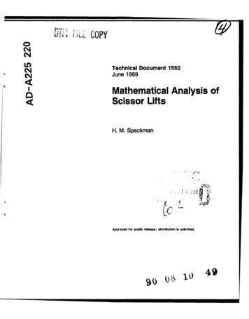
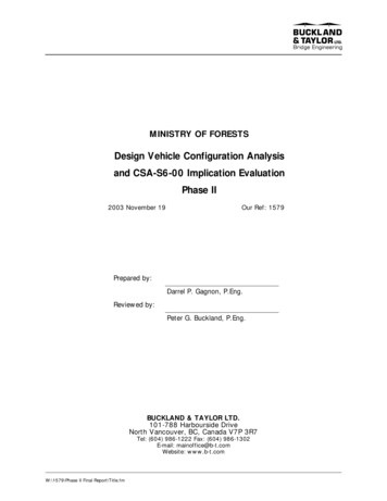
Int. J. Mech. Eng. & Rob. Res. 2015Manoj R Patil and S D Kachave, 2015Figure 2: Displacement Contour of the Entire Jack at 23102 N Load330
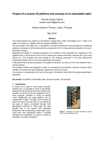
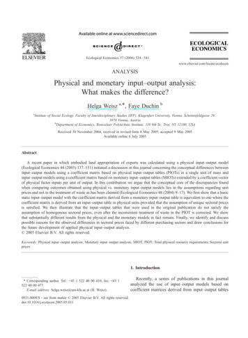
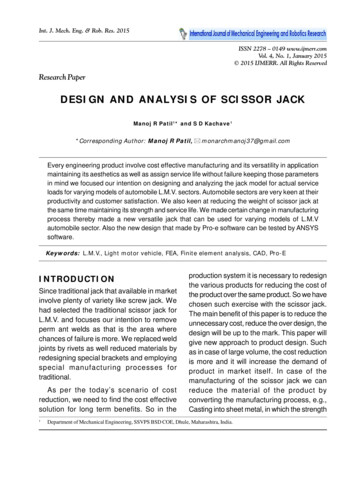
Int. J. Mech. Eng. & Rob. Res. 2015Manoj R Patil and S D Kachave, 2015Figure 3: Von-Mises Stress Contour of the Entire Jack at 23102 N Load331
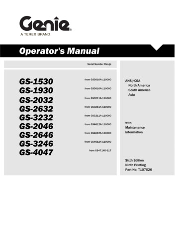
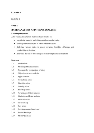
Int. J. Mech. Eng. & Rob. Res. 2015Manoj R Patil and S D Kachave, 2015Figure 4: Cap-Von Mises Stress ContourFigure 5: Base-Von Mises Stress Contour332
Int. J. Mech. Eng. & Rob. Res. 2015Manoj R Patil and S D Kachave, 2015Figure 6: Base Rivet-Von Mises Stress ContourFigure 7: Lower Arm-Von Mises Stress Contour333
Int. J. Mech. Eng. & Rob. Res. 2015Manoj R Patil and S D Kachave, 2015Table 1: Material PropertiesMaterialTensile Yield StrengthPoisson’s RatioModulus of ElasticitySAE J1392 050YLF344 Mpa0.3200000 MpaSAE 1018410 Mpa0.3200000 MpaTable-2: Data analysis of scissor jackPart NamesCapBaseBase rivetCap rivetLower armsUpper armsScrewYield Stress(Mpa)344344410410344344410Failure Strain(%)20%20%20%20%20%20%20%Load to Yield(Kgs)2355117711771577117715772355Plastic Strain at2355 Kg Load (%)0.01740.283.283.051.890.5950.599conditions subjected to point load onupper cap of 2033 kgs is shown in Tables1 and 2. The maximum strain in the Base Rivet 3.28%. The maximum strain in the Cap Rivet 3.05%.CONCLUSION Mass of the Jack in Kg 1.824 Kg.The paper will include a scissor jack ofautomobile L.M.V. vehicle and other same typeof variants. This proposed design of scissorjack after its stress analysis concludes that:Project BackgroudModel: Top channel, bottom channel, Baseand Cap modeled with shell elements andbearing, Trunions, Base Rivet, Cap Rivet andScrew are modeled with Hexa and Pentaelements.This is a common jack for the variant(satisfying the product requirements).The proposed jack has the reduced weight (bychanging the manufacturability).Loading: The point load of 2,355 kgs appliedon the top surface of the cap (23102 N appliedon the top surface of cap by using rigid) afterthat unloading (for permanent set analysis) thepoint load to 1.47 N.Designing this new jack reduces the no. ofparts for simplifying the assembly process.Only rivet joints are induced (Removal ofwelding to avoid distortion).Boundary Conditions: Bottom face of theBase is constrained to all the DOF and matingparts are connected with rigid links.REFERENCES1. Chang Shoei D and Liaw Huey S (1987),“Motor Driven Scissor Jack forAutomobiles”, US Patent Number4653727, Da Li Hsien, TW.RESULTSData analysis of scissor jack static loading334
Int. J. Mech. Eng. & Rob. Res. 2015Manoj R Patil and S D Kachave, 20152. Farmer Dennis E (2001), “Automatic Jackand Wheel Change System”, US PatentNumber 6,237,953, Mt. Gay, WV.7. Nakasone Y, Yoshimoto S and StolarskiT A (2006), Engineering Analysis withANSYS Software, 1st Edition, ElsevierButterworth-Heinemann.3. Huang Chen-Ti and Chou Ching-Hsing(2001), “Directly Driving ElectromotiveJack Device for Releasing TorsionalForce”, US Patent Number 6,299,138,Taipei, TW.8. Pickles Joseph (1988), “PortablePowered Screw Jack Actuator Unit”, USPatent Number 4,749,169, Troy, MI.9. Prather Thomas J (2009), “Vehicle LiftSystem”, US Patent Number 7,472,889,Rock Springs, WY.4. Kathryn J De Laurentis and MirceaBadescu (2001), Pro-E Tutorial, MB,Hinge Assembly Tutorial.10. Whittingham Reginald P (1990), “VehicleJack”, US Patent Number 4,969,631,Tustin, CA.5. Mahadevan K (2011), Design Data HandBook for Mechanical Engineers, 3 rdEdition, CBS Publisher.6. Mickael Emil (2004), “Motor DrivenScissor Jack with Limit Switches”, USPatent Number 6,695,289 B1.335
scissor jack. This crank is usually “Z” shaped. The end fits into a ring hole mounted on the end of the screw, which is the object of force on the scissor jack. When this crank is turned, the screw turns, and this raises the jack. The screw acts like a gear mechanism. It has teeth (the screw thread), which turn and move the two arms, producing work. Just by turning thisFile Size: 812KBPage Count: 9