Transcription
Lonworks Damper Interface catalogue Release: 1.9 AUGUST 2017Lonworks Damper Interface CatalogueTwo Position, Three Position & Hot Smoke Fire Damper InterfaceThis product forms part of a life safety system. Failure to correctlystore, handle, install and maintain the product will directly put atrisk the lives of the occupants and the fabric of the building.- PAGE 1 -Always READ this document BEFOREINSTALLATION. Please Retain forfuture reference.
Lonworks Damper Interface catalogue Release: 1.9 AUGUST 2017SFDI-FT / FDI-FT / SDI-FT230V / 120V / 24Vtwo positionDamper Interfacethe Actionair Damper Interface provides a completeLonworks communication device to control dampers.safegard developed the Lonmark functional profile (11001) forsmoke fire dampers and this has been adopted worldwide .ELECTROSTATIC SENSITIVE DEVICET wo Position Smoke Fire Damper Interface Options:sfDI - ftthe Actionair Smoke Fire Damper Interface provides a complete Lonworks communication device tocontrol any failsafe spring-return smoke fire damper actuator that incorporates two auxiliary switches.fDI - ftthe Actionair Fire Damper Interface provides a complete Lonworks communication device to failsafe, viaan electromagnet, any spring-return fire damper. monitoring of the open and/or closed position is optional.sDI - ftthe Actionair Smoke Damper Interface provides a complete Lonworks communication device to controlany open/closed smoke damper actuator that incorporates two auxiliary switches.Please note: Each interface is available in 24V, 120V, or 230V. Please specify a voltage at time of order.- PAGE 2 -
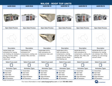
Lonworks Damper Interface catalogue Release: 1.9 AUGUST 2017Mounting Diagram200Preparation75 Only trained and qualified personnel should be allowed toinstall, replace or service this equipment. Installation shouldbe in accordance with the relevant local safety standards. The connectors can accommodate cable diameters up to2.5mm2. It is recommended that all wires be crimped to easeinstallation and replacement of the product. The mains wiring should comply with IEC 60227 or IEC 60245. A switch or circuit breaker should be included as part of theinstallation. The switch or circuit breaker should meet the relevantrequirements of IEC 60947-1 and IEC 60947-3. The switch or circuit breaker should be in close proximity tothe equipment and be within easy reach of the operator. The switch or circuit breaker should be marked as thedisconnecting device for the equipment and shoulddisconnect both poles of the supplyaprox 256016015aprox 25Four mounting holesØ 6mm for mountingwith suitable screwsdepending on whethermounting to a duct,block wall or stud wall.120220Dimensions in mm.Installation1.10Dimensions and MountingThe compact and robust design of the interfaceenclosure allows the unit to be mounted to a duct,block wall or stud wall.Ensure the Interface is located close enough tothe actuator/damper it is controlling/monitoring.Normally, actuator/electromagnet leads are 1m inlength. Also, ensure the Interface is accessible forfuture maintenance purposes.2. W wire the interface in accordance with the wiring diagramsshown following. If the actuator is to be located more than 5mfrom the Interface then contact Actionair systems fortechnical assistance.3. Please be aware that the switch and auxiliary inputs arenot optically isolated. It is recommended that the optionaldetectors (smoke or heat) use failsafe open contacts toguarantee their detection in the event of a fault condition.It is also recommended that the network cables are not runalongside any high voltage or high frequency sources. Also,network cables must not be mixed on an individual networkas they have very different electrical characteristics and couldrender the system unreliable.Please note: 150mm clearance required for lid removal andat cable entry points. Unused cable entries should be sealed withblind washers. Do not drill the enclosure as this will affect itsIP rating.Disconnect the local supply before commencing any workon the Interface.4.If FDI-FT, the electromagnet failsafe realease is optional. Ifused, the electromagnet must be protected by a suitablesnubber device.5.If FDI-FT, the monitoring of the damper positions is optional.6. Once wiring is complete, apply power to the DI-FT. The greenpower LED should illuminate to indicate the presence ofpower.7.- PAGE 3 -the Interface is now ready to be configured using a standardLonworks tool such as Lonmaker or the Actionair system.
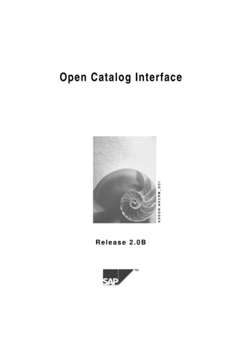
Lonworks Damper Interface catalogue Release: 1.9 AUGUST 2017SFDI-FT Wiring: 230V & 120VSFDI-FT Wiring: 24VThermalTripSAFEGARDSGS230-TTo Heat DetectorActuator Example230VActuator DriveS62ActuatorPositionSenseS4SDS624VActuator DriveS2 S11OPTIONALTo Heat DetectorActuator ExampleHDTo ctuatorPositionSenseACTUATOR DRIVEL NSWITCH INPUTSAUX1AUX2S6 S4S2S1-Aux InputsACTUATOR DRIVE- Green LEDYellow LEDSWITCH INPUTSAUX1AUX2S6 S4S2S1-- L NNETWORKService Pin-POWER INNETWORKNetworkNetworkService LEDBlue LEDService PinPOWER INPower LEDRed LEDYellow LEDService LEDBlue LED1AT-Green LEDPower LEDRed LED- LSDS2 S112Aux InputsF1HDTo SmokeDetector OR-NETWORKNETWORKNetworkNetwork-24V ACN24V DCFDI-FT Wiring: 230V & 120VOPTIONALFireDamperElectromagnetfailsafe releaseTo Heat DetectorTo Electromagnetfailsafe releaseHDCLOSEDOPENFDI-FT Wiring: 24VOPENSDTo Heat DetectorTo SmokeDetectorDamperPositionSenseAux InputsACTUATOR DRIVE SWITCH INPUTSF1L NOPENCLOSEDAUX1AUX2 -ACTUATOR DRIVE --SWITCH INPUTSOPENCLOSEDAUX1AUX2 --Green LEDPower LEDRed LEDYellow LED L NNETWORKNetworkService LEDBlue LEDService PinPOWER INPower LEDRed LEDYellow LEDService LEDBlue LED1ATSDAux InputsGreen LEDService Pin-POWER INNETWORKNetwork- LHDCLOSED-N24V DC- PAGE 4 -NETWORK OR-24V ACNetworkNETWORKNetwork
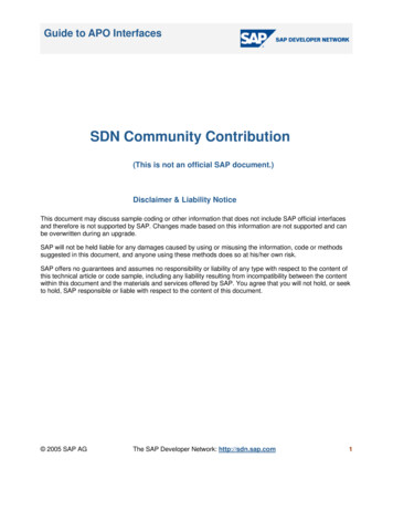
Lonworks Damper Interface catalogue Release: 1.9 AUGUST 2017SDI-FT Wiring: 230V & 120VBELIMOBE230SDI-FT Wiring: 24VBELIMOBE24OPTIONALTo Heat DetectorActuator ExampleS6S4ActuatorPositionSenseActuator ExampleHDTo SmokeDetectorOPTIONALTo Heat DetectorSDS6S2 S1212L1 N L2SWITCH INPUTSAUX1AUX2S6 S4S2S1-Aux Inputs 1- 2SWITCH INPUTSAUX1AUX2S6 S4S2S1--Green LEDPower LEDRed LEDYellow LED L NNETWORKNetworkService LEDBlue LEDService PinPOWER INPower LEDRed LEDYellow LEDService LEDBlue LED1ATSD3ACTUATOR DRIVE-Green LEDService Pin-POWER INNETWORKNetwork- L124VActuator DriveAux InputsACTUATOR DRIVEHDTo SmokeDetectorS2 S13230VActuator DriveF1S4ActuatorPositionSense-NETWORK OR-NETWORKNetworkNetwork24V ACN24V DCMaintenanceLED Behaviour24V AC/DC version5 x 20mm, Time-Lag Fuse, 2A rated (see F1 on wiringdiagrams); for example Littlefuse 215 seriesFunction Green Red Yellow120/230VAC versions5 x 20mm, Time-Lag Fuse, 1A rated (see F1 on wiringdiagrams); for example Littlefuse 215 seriesOpenOnOffClosedOffOnBlueTravelling Flashing FlashingFault FlashingPing One-shotOffline On On On OnWink function: Service LED flashes for 5s- PAGE 5 -
Lonworks Damper Interface catalogue Release: 1.9 AUGUST 2017LonMark ObjectsNode objectMandatory network variablesnv1nviRequestSNVT obj requestnv2nvoStatusSNVT obj statusnv4nvoAlarmSNVT alarmnv2nvoActuPosnSNVT hvac emergnv3nvoActuDriveFbSNVT hvac emergOptional network variablesFSDA objectMandatory network variablesnv1nviActuDriveSNVT hvac emergOptional network variablesConfiguration propertiesMandatoryOptionalnc45 Drive Timenc48 Receive Heartbeatnc44 Safety Positionnc30 Turn Off Timenc41 Actuator Labelnc146 Installation Datenc17 Location Labelnc147 Maintenance Datenc148 Manufacture Datenc61 OEM Labelnc49 Send Heartbeatnc141 Zone Number- PAGE 6 -
Lonworks Damper Interface catalogue Release: 1.9 AUGUST 2017Two Position Smoke Fire Damper Interface SpecificationsLonWorksNeuron chipEnvironmentalFT5000Operating temperature-5 C to 70 CTransceiver type FT-X2Storage temperature-20 C to 70 CService functions Service pin, service LED andneuron ID self-adhesive tagHumidity25 % RH to 90 % RH at 70 CMaximum altitude2000 mSupply(please specify at time of order)Input voltages(230 23) V AC, 50 Hz(120 12) V AC, 60 Hz(24 4.8) V AC, 50 Hz(24 2.4) V DCMaximum power consumption 2.5 WOutputContact typeDPCO mechanicalrelay contactsMaximum switched load25 VAAgency Listings CEEMC EN60730-1:00 A1:04 A2:08 A16:07 CISPR 22 /FCC part 15, cl. BLVDEN60730-1:2005 A2:2008LonMark11001EnclosureMaterial ABS base with polycarbonate lidIP ratingIP 54Flammability UL 94V-0InputsContact type Non-isolated dry contactsSense currentConformance10 mAPollution Category 2Dimensions (excl glands)200 mm x 120 mm x 75 mm(L x W x D)Dimensions (incl glands)200 mm x 170 mm x 75 mm(L x W x D)Note:Optional HDIE available: 300 C for 2 hour or 600 C for ½ hour applications.please refer to Hot enclosures catalogue or contact Actionair for details.- PAGE 7 -
Lonworks Damper Interface catalogue Release: 1.9 AUGUST 20173PSFDI-FT24V 25 VAthree positionDamper Interfacethe Actionair 3psfDI-ft provides a complete Lonworks device tocontrol a single modulating actuator that incorporates two auxiliaryswitches.ELECTROSTATIC SENSITIVE DEVICEThree Position Smoke Fire Damper Interface Options:Auto ModeDamper can be set to a balance position or drive open/closed and failsafe via spring-return or drives to thefailsafe position.Local ModeDamper can be modulated via a 2-10V signal from the BMS and only instructed to failsafe by the system in theevent of a fire alarm/fireman’s override input.- PAGE 8 -
Lonworks Damper Interface catalogue Release: 1.9 AUGUST 2017Dimensions and MountingMounting DiagramThe compact and robust design of the interfaceenclosure allows the unit to be mounted to a duct,block wall, or stud wall.Ensure the interface is located close enough tothe actuator it is controlling/monitoring. Normallyactuator leads are 1 m in length. Ensure the interfaceis accessible for future maintenance purposes.20075aprox 256016015Please note: 150mm clearance required for lid removal andat cable entry points. Unused cable entries should be sealed withblind washers. Do not drill the enclosure as this will affect itsIP rating.aprox 25Four mounting holesØ 6mm for mountingwith suitable screwsdepending on whethermounting to a duct,block wall or stud wall.120Dimensions in mm.22010- PAGE 9 -
Lonworks Damper Interface catalogue Release: 1.9 AUGUST 2017PreparationACTUATOR DRIVEDisconnect the local supply beforecommencing any work on the interface.F124V GND YIt is recommended that the network cablesare not run alongside any high voltage or highfrequency sources. Network cables should notbe mixed on an individual network as theyhave very different electrical characteristicsand could render the system unreliable.The interface is now ready to be configuredusing the Safegard Builder installation tool.To BMSY1GNDFrom BMSC3US6S4GreenRedYellowBlueS2C4U1 GND Y1 GNDS1Learn SwitchLearn LEDPower LEDService LEDService Pin- GNDC1NETWORKC1 NetworkC1- -ORGNDC6POWER IN4. Once the wiring is complete, apply power tothe interface.5.U1GNDACT AUX SWITCHES LOCAL CONTROLC22. W wire the interface in accordance with thewiring diagram shown across. If the actuatoris located more than 5 m from the interface,then contact Actionair for technicalassistance.3.LOCAL ModeThe connectors can accommodate cablediameters up to 2.5 mm2. It is recommendedthat all wires are crimped to ease installationand replacement of the rSetpointpotentiometer Only trained and qualified personnel shouldbe allowed to install, replace, or servicethis equipment. Installation should be inaccordance with the relevant local safetystandards.Status LEDs Wiring Diagram 3PSFDI-FT in enclosure without lid C5NETWORKNetwork-24V AC24V DCReplacement Fuse2 A time-lag fuse (see F1 on wiring diagram).Suggested replacement: Littelfuse 215 series.ConnectorDescriptionC1-124 V powerC1-2 GNDC2-4 Actuator 24 VC2-3 Actuator GNDC2-2 Actuator Y signalC2-1 Actuator U signalC3-4 S6C3-3 S4C3-2 S2C3-1 S1- PAGE 10 -ConnectorDescriptionC4-4 U1 to BMSC4-3 GND to BMSC4-2 Y1 from BMSC4-1 GND from BMSC5-1GND (do not connect)C5-2NetworkC5-3NetworkC6-1 GND (do not connect)C6-2 NetworkC6-3 Network
Lonworks Damper Interface catalogue Release: 1.9 AUGUST 2017Auto ModeStatus LEDsThermalTripModulatingactuatorFunction Green Red YellowOpenOnOffClosedOffOnBlueBalanced On OnTravelling Flashing FlashingFault FlashingPing One-shotOffline On On On OnWink function: Service LED (yellow) flashes for 5sACT AUX SWITCHESF124V GND Y- C3US6Status LEDsC2S4GreenRedYellowBlueS2C4U1 GND Y1 GNDS1SetpointpotentiometerACTUATOR DRIVEGNDC1GNDC6POWER INNETWORKNetworkC5NETWORKNetwork- PAGE 11 -Smokecontrolsystem
Lonworks Damper Interface catalogue Release: 1.9 AUGUST 2017Learn ModeModulatingactuatorFunction Green Red YellowLearn24V GND Y-C3US6Status LEDsF1On/OffOn/OffACT AUX SWITCHESC2S4GreenRedYellowBlueS2C4U1 GND Y1 GNDS1SetpointpotentiometerACTUATOR DRIVE Status LEDsThermalTripGNDC1GNDC6POWER INNETWORKNetwork- PAGE 12 -Learn Switch on2Rotate the potentiometer to 0%to fully close the damper3Use the potentiometer to balancethe damper in the required position- The Learn LED illuminates when theactuator is within 2º of the setpoint4Service Pin (hold for 1sec)5C5NETWORKNetwork1Learn Switch offSmokecontrolsystem
Lonworks Damper Interface catalogue Release: 1.9 AUGUST 2017Local ModeStatus LEDsThermalTripModulatingactuatorFunction Green Red YellowLocal OnBUILDINGMANAGEMENTSYSTEMACT AUX SWITCHES LOCAL CONTROLF124V GND Y- C3US6Status LEDsC2S4GreenRedYellowBlueS2C4U1 GND Y1 GNDS1SetpointpotentiometerACTUATOR DRIVEGNDC1GNDC6POWER INNETWORKNetworkC5NETWORKNetwork- PAGE 13 -Smokecontrolsystem
Lonworks Damper Interface catalogue Release: 1.9 AUGUST 2017Three Position Smoke Fire Damper Interface SpecificationsLonWorksNeuron chipEnvironmentalFT 5000Operating temperature-5 C to 70 CTransceiver type FT-X2Storage temperature-20 C to 70 CService functions Service Pin, Service LED, andNeuron ID self-adhesive tagHumidity25 % RH to 90 % RH at 70 CMaximum altitude2000 mSupplyInput voltage(24 4.8) V AC, 50 Hz(24 2.4) V DCMax power consumption1.3 WEMC EN 60730-1:00 A1:04 A2:08 A16:07Agency listingsCEEnclosureOutputContact type SPST mechanicalrelay contactMax switched loadConformance25 VAMaterial ABS base with polycarbonate lidIP ratingIP 54Flammability UL 94V-0Pollution Category 2InputsContact type Non-isolated dry contactsDimensions (excl glands) 200 mm x 120 mm x 75 mm(L x W x D)Sense currentDimensions (incl glands)10 mANote:Optional HDIE available: 300 C for 2 hour or 600 C for ½ hour applications.please refer to Hot enclosures catalogue or contact Actionair for details.- PAGE 14 -200 mm x 170 mm x 75 mm(L x W x D)
A l s o ava i l a b l e f r o m Sa f ega r dDampers······Smoke/Fire dampersFire dampersVCD’sShut-off dampersAccess doorsIndustrial & heavy duty dampers (UL approved)Complies with European standardsWARNING: The responsible body shall be made aware that, if the equipment is used in a manner not specified by themanufacturer, the protection provided by the equipment may be impaired.The information herein is subject to change without notice. We do not assume any liability arising out of the use of this product. Purchaseof goods and services is subject to Actionair standard terms and conditions.Product warranty 12 months from date of delivery.Actionair and Safegard are brand names of Swegon Air Management and SafegardSystems respectively and both companies are part of the Swegon Group.Swegon Air Management, South Street, Whitstable, Kent, CT5 3DU, UKT: 01227 276100 F: 01227 264262 E: sales@actionair.co.uk www.actionair.co.ukUnit 33, Southern Cross Business Park, Bray, Co. Wicklow, A98 HT99, IrelandT: 353 1 2761600 F: 353 1 2761611 E: info@safegard.ie www.safegard.ie
Lonworks Damper Interface cataL ogue reLease: 1.9 august 2017 - PAGE 1 - Lonworks Damper Interface catalogue two position, three position & Hot smoke fire Damper Interface this product forms part of a life safety system. ailure to correctly f store, handle,