Transcription
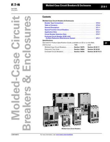
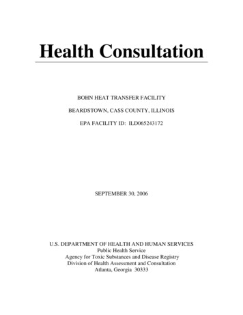
Technical Information: Thermal ManagementHeat Dissipation in Electrical EnclosuresSpec-00488DPH (763)(763) 422-2600422-2211FXTechnical InformationThermal ManagementHeat Dissipation in Electrical EnclosuresHeat Dissipation in Sealed Electrical EnclosuresThe accumulation of heat in an enclosure is potentially damaging to electrical and electronic devices. Overheating can shorten the lifeexpectancy of costly electrical components or lead to catastrophic failure.Enclosure MaterialsThe following discussion applies to gasketed and unventilated enclosures. Higher temperature rises can be expected with unfinishedaluminum and unfinished stainless steel enclosures due to their material’s less efficient radiant heat transfer. Non-metallic enclosures havesimilar heat transfer characteristics to painted metallic enclosures, so the graph can be used directly despite the difference in material.Enclosure Surface AreaThe physical size of the enclosure is the primary factor in determining its ability to dissipate heat. The larger the surface area of the enclosure,the lower the temperature rise due to the heat generated within it.To determine the surface area of an enclosure in square feet, use the following equation:Surface Area 2[(A x B) (A x C) (B x C)] 144where the enclosure size is A x B x C in inches.This equation includes all six surfaces of the enclosure. If any surface is not available for transferring heat (for example, an enclosure surfacemounted against a wall), that surface’s area should be subtracted. Note: Enclosure volume cannot be used in place of surface area.Enclosure Heat InputFor any temperature rise calculation, the heat generated within the enclosure must be known. This information can be obtained from thesupplier of the components mounted in the enclosure.Enclosure Temperature Rise (ΔT)The temperature rise illustrated by the curves in the Sealed EnclosureTemperature Rise graph is the temperature difference betweenthe air inside a non-ventilated and non-cooled enclosure and theambient air outside the enclosure. This value is described in thegraph as a function of input power in watts per square foot. In orderto predict the temperature inside the enclosure, the temperature riseindicated in the graph must be added to the ambient temperaturewhere the enclosure is 1214Temperature Rise AboveAmbient (ºC)Research has shown for every 18 F (10 C) rise above normal roomtemperature 72 - 75 F (22 - 24 C), the reliability of electroniccomponents is cut in half.Temperature Rise AboveAmbient (ºF)Sealed Enclosure Temperature Rise12016Input Power (Watts/Square Foot)Unfinished Aluminum and Stainless Steel EnclosuresPainted Metallic and Non-metallic EnclosuresDetermining Temperature RiseThe temperature rise inside a sealed cabinet without forced ventilation can be approximated as follows.First calculate the surface area of the enclosure and, from the expected heat load and the surface area, determine the heat input power inwatts/ft.2Then the expected temperature rise can be read from the Sealed Enclosure Temperature Rise graph. Find where the input power intersectsthe line for the enclosure material and read the approximate expected temperature rise at the left.Example:What is the temperature rise that can be expected from a 48 x 36 x 16 in. painted steel enclosure with 300 W of heat dissipated within it?Solution:Surface Area 2[(48 x 36) (48 x 16) (36 x 16)] 144 42 ft.2Input Power 300 42 7.1 W/ft.2From the Sealed Enclosure Temperature Rise graph:Temperature Rise approximately 30 F (16.7 C)Safety MarginsThe graph provides only an approximation of temperature rise. Actual temperature rise will vary due to enclosure layout, internal fan use, airmovement in the vicinity of the enclosure, and other factors. A safety margin should be used in critical applications. A safety margin of 25% isrecommended.Outdoor ApplicationsIn outdoor applications where an enclosure is exposed to the sun, the temperature inside the enclosure can rise significantly above theestimates calculated. See the Solar Heat Gain section for further technical information.Subject to change without noticePH (763) 422-2211 FX (763) 422-2600 hoffmanonline.com 2011 Pentair Technical ProductsSpec-00488 D1
Technical Information: Thermal ManagementHeat Dissipation in Electrical EnclosuresCirculating FansThe use of circulating fans in an enclosure will improve heat dissipation by as much as 10 percent. Circulating fans are most commonlyemployed to eliminate hot spots inside an enclosure. The Sealed Enclosure Temperature Rise graph approximates the “average” temperaturerise inside an enclosure. However, the temperature in the vicinity of a critical component can be much higher if it is producing a significantportion of the heat in the enclosure or if it is located near a large heat producing device. An internal circulating fan eliminates the resultinghot spots by mixing the air inside the enclosure.Cooling Options AvailableHoffman offers a full line of enclosure cooling products to meet the unique needs of many applications. These products include fansfor circulation and ventilation as well as heat exchangers and air conditioners for closed loop cooling. Hoffman Authorized Distributors,Representatives, and factory technical applications support personnel are qualified to assist you in meeting your cooling requirements.GlossaryBTU/hr. British Thermal Units/hour. One BTU is the amount of heat required to raise the temperature of one pound of water by one degreeFahrenheit.Watts (W) The thermal (heat) load in the enclosure is measured in watts. One watt 3.413 BTU/hr.CFM Airflow in cubic feet per minute (ft.3/min.)ΔT Change in temperature (1.8 ΔT F 1.0 ΔT C) F Degrees Fahrenheit C Degrees CelsiusSolar Heat GainWhen evaluating the thermal management needs of outdoor electrical enclosures, solar heat gain must be considered. Variables thataffect the enclosure’s internal temperature rise include the amount of solar exposure, enclosure color and material type, highest sustainedatmospheric temperature, heat build-up from internal components and heat reflectance from the surrounding environment.2Subject to change without noticePH (763) 422-2211 FX (763) 422-2600 hoffmanonline.com 2011 Pentair Technical ProductsSpec-00488 D
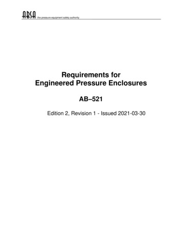
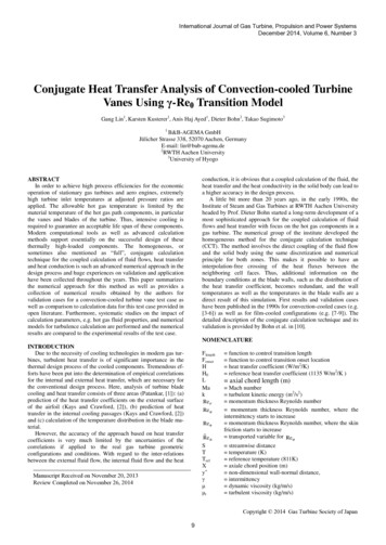
Technical Information: Thermal ManagementHeat Dissipation in Electrical EnclosuresExposure to Solar RadiationOver much of the United States, the approximate peak values of solar radiation striking the Earth’s surface is 97 W/ft.2 and the ambient airtemperature can reach 104 F. Altitude, humidity and air pollution have an impact on these values, even more so than the location’s latitude. Inthe high, dry climates of the southwest, solar radiation values of 111 W/ft.2 and air temperatures greater than 104 F can be reached.The extreme conditions the enclosure will be exposed to should be identified. If the internal enclosure temperature is greater than theoutdoor (ambient) temperature, wind will provide greater heat transfer and thus cool the enclosure. But, because the presence of windcannot be guaranteed, it is usually not taken into account when establishing a worst-case evaluation.Effect of Surrounding LocationReflection of solar energy from the foreground and surrounding surfaces can impact the total amount of radiant exposure by as much as 30percent.Effect of Enclosure Color and FinishThe percent of solar energy absorbed by the enclosure depends on surface color, finish and texture. Absorption values of the finish willincrease with age.Standardized Test EvaluationTelcordia NEBS GR-487 provides a test procedure for evaluating the solar load on electrical/electronic enclosures. The test is run with theinternal electronics on, in an environmentally controlled room, and three sides of the enclosure are illuminated uniformly with controlledbanks of lights to a measured surface radiant value of 70 W/ft.2 The temperature rise inside the enclosure above ambient is added to 115 F (46C). This temperature total must not exceed the lowest-rated component within the enclosure.To evaluate the heat load on an enclosure, you must take intoaccount: Total surface area of the enclosure Color of the enclosure Internal heat load Maximum allowable internal temperature Maximum ambient temperature Solar loadExamples:1. What amount of heat energy must be removed from a 24 x20 x 12 (surface area 14 ft.2) ANSI 61 gray enclosure locatedoutdoors and without any heat dissipated internally, tomaintain the enclosure temperature equal to the ambient(temperature rise 0 degrees)? From the chart below, at 0 Ftemperature rise we find the solar load is approximately 14W/ft.2 (14 ft.2 x 14 W/ft.2 196 W). This is the heat energy thatmust be removed to maintain the enclosure temperature atambient.2. If the same enclosure has internal equipment dissipating200 W of heat, what is the amount of heat energy that mustbe removed to maintain the enclosure at a temperaturerise of 20 F above the ambient temperature? From the chartbelow, at 20 F temperature rise we find the solar load isapproximately 6 W/ft.2 (14 ft.2 x 6 W/ft.2 84 W). All of theinternally dissipated heat of 200 W must also be removed. 84W 200 W 284 W. This is the total amount of heat energythat must be removed to maintain the enclosure at 20 Fabove the ambient temperature.Subject to change without notice3. What is the expected temperature rise above the ambienttemperature due to solar heat gain for an enclosure withANSI 61 gray finish? From the chart below, the temperaturerise due to solar heat load can be found by locating theintersection of the data curve for the given finish and the0 Solar Generated Heat Load axis. For ANSI 61 gray, thetemperature rise due to solar heat is about 40 F.Solar Load Based on Color and Temperature Rise50 T (Internal Temp. - Ambient Temp.) FEvaluation of Solar Heat Gain40302010051015202530Solar Load (watts/ft2)BlackLight ColorGrayWhitePH (763) 422-2211 FX (763) 422-2600 hoffmanonline.comMetallic 2011 Pentair Technical ProductsSpec-00488 D3
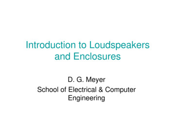
Technical Information: Thermal ManagementHeat Dissipation in Electrical EnclosuresThe Benefits of Shielding EnclosuresThe results of the test show the enclosure with top and side shields tohave approximately a 46 percent reduction in temperature compared tothe unshielded enclosure. The reduction in temperature is approximately25 percent with the solar top shield only. Hoffman offers top shields as anaccessory for Hoffman COMLINE Wall-Mount Enclosures. Hoffman canprovide side shields as a customer-ordered modification.Shielding E ec tiveness115Temperature ( F)105Hoffman’s research on the effects of solar radiation on enclosureshas shown the positive benefits of utilizing shielding to decreasetemperature rise. Shielding has been found to be an effective,low-cost method of reducing solar heat gain in outdoor electrical/electronic applications.A test to compare the shielding effect on internal temperature rise wasperformed on similar enclosures exposed to the sun. The enclosures arethe same color (RAL 7035 light gray) and material. The enclosure onthe left is unshielded; the enclosure on the right is shielded on top andapplicable sides.4Subject to change without notice9585No ShieldSide ShieldTop and Side ShieldOutside Temperature753:00 a.m.Enclosure TypeUnshieldedTop shield onlyTop and side shields7:00 a.m.Temperature (F)119114110PH (763) 422-2211 FX (763) 422-2600 hoffmanonline.comNoonJuly 29, 1999Temperature (C)4846434:30 p.m.Percent Temperature Reduction—2546 2011 Pentair Technical ProductsSpec-00488 D
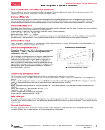
Technical Information: Thermal ManagementFan/Blower Selection and SizingFan/Blower Selection and SizingSelection ProcedureThe following selection process will help determine the size of the fan required for your application.Application Guidelines Forced air systems can provide much greater heat transfer rates than those available with natural convection and radiation, thereforeinternal electronic packages have lower hot spot temperatures with forced air systems. The amount of cooling air flowing through anenclosure determines the temperature rise inside the enclosure due to the heat input. The more air that flows through the enclosure, thelower the temperature rise. F ans can be used at the exhaust to draw air through an enclosure, or at the inlet to blow air into the enclosure. Generally, a blowing fan atthe air inlet is recommended for the following reasons:1. A fan at the inlet will raise the internal air pressure within the enclosure, which will help to keep dust and dirt out of an enclosure thatis unsealed or opened frequently.2. A blowing fan at the inlet will produce slightly more turbulence, which improves the heat transfer characteristics within theenclosure.3. Fan life is prolonged since it is located in the path of the entering cooler air. T he air inlet to the enclosure should be located as far as possible from the air outlet in order to prevent the airstream from short cycling. Ina short cycling condition the air leaving the enclosure through the air outlet re-enters the enclosure through the air inlet. This conditionresults in a reduction in cooling efficiency. In general, it is recommended that the enclosure air inlet be on the side of the enclosure nearthe bottom and the air outlet be located on the opposite side and near the top. F ans should not be located adjacent to an area that restricts the free flow of cooling air. The use of a plenum in front of the fan is agood practice since it improves fan performance. The air velocity must be allowed to develop in order to effectively overcome the flowresistance. When the fan blades are located at the downstream end of the plenum housing, the air has a longer flow path. This improvesthe air velocity profile and fan performance. The enclosure fan system should have an air outlet area at least equal to the air inlet area. T he system cooling efficiency changes with altitude because of reduced air density. Airflow through an enclosure should be increasedwhen the air density decreases. If more than one fan is used in parallel, in the same enclosure, then both fans should be identical.Fans and BlowersDetermine the required fan/blower size (volume airflow):Step 1Select the product family that best fits your application: Compact Cooling Fans(economical fan with no filter) Cooling Fan Packages(economical fan package with low density filter) Type 12 Cooling Fan PackageCFM Required airflow in ft3/min.Example:An internal heat load of 400 W requires airflow of about 63 CFMto maintain the enclosure at a ΔT of 20 F above the ambienttemperature.(3.16 x 400 W) / (20 F) 63 CFMStep 2Determine the internal heat load in watts.1 W 3.413 BTU/Hr.Step 3Determine the ΔT ( F)Step 4Plot your application using the selection graph to the right. Find Watts (internal heat load) on the vertical scale Draw a horizontal line across to the intersection point with thediagonal line representing your ΔT Extend a vertical line down to the horizontal scale to determineyour CFM requirementThe red line on the chart shows the airflow requirement for a 400 Wheat load and a ΔT of 20 F.Or calculate using the formula:CFM (3.16 x Watts) / (ΔT F)Where:Watts Internal Heat Load in wattsΔT Internal Temperature minus Ambient Temperature in FSubject to change without noticePH (763) 422-2211 FX (763) 422-2600 hoffmanonline.com 2011 Pentair Technical ProductsSpec-00488 D5
Technical Information: Thermal ManagementFan/Blower Selection and SizingThermal Management Sizing and SelectionSoftware6Subject to change without noticeDesigned to assist you in determining the most suitable choicesof air conditioners, heat exchangers or fans for your application.Download a free copy of our selection software by visiting our website: hoffmanonline.com.Click on Thermal Management chapter.PH (763) 422-2211 FX (763) 422-2600 hoffmanonline.com 2011 Pentair Technical ProductsSpec-00488 D
5 Technical Information: Thermal Management Fan/Blower Selection