Transcription
User ManualIP Camera User Manual1
User ManualContentsIntroduction . 31. Overview . 41.1 Range of Application. 41.2 Product Description. 51.3 Operation Environment . 52. Device Connection . 63. Device Operation Instructions . 73.1 Check Connection . 73.2 Searching Device . 83.3 Installation of Controls and Login to System .113.3.1 Preview .123.3.2 Playback(optional function) .144 Parameter Setting.164.1 Display Configuration .164.2 Image Control .184.3 Video Blocking .194.4 ROI (if applicable) .205.Record Parameters .215.1Rec Parameters.215.2Schedule .216. Network Parameters .226.1 Network Parameters .226.2 Bit stream setting.246.3 E-Mail Configuration .256.4 DDNS Configuration .276.5 IP Filtering .286.6 RTSP .286.7 FTP .301
7. Alarm Parameter .317.1 Mobile Detection .317.2 I/O Alarm (if applicable) .337.3 Lens Blocking.338. Device .348.1 SD Card(optional function) .348.2 Audio .358.3 Logs .359. System Parameters.369.1 Basic Information.3610. Advanced.4010.1 System Update .4010.2 Default Parameters .4010.3 System Maintenance .4111. Intelligent .4211.1 Smart Schedule .4211.2 Smart Analysis.4311.3 Perimeter Intrusion Detection(PID) .4311.4Line Crossing Detection(LCD) .4411.5 Stationary Object Detection.4511.6 Pedestrian Detection(PD) .4711.7 Face Detection(FD) .4811.8 Cross Counting(FD) .492
IntroductionThank you for using our network camera products. Our network camera products are integrated anddeveloped for network video monitoring, including Storage Network Bullet, Wireless Storage NetworkBullet, IR Network Dome, IR Network Weather-Proof Cameras and High-Speed Network Ball.High-performance single SOC chips are used in media processor for audio/video acquisition,compression and transmission/transfer. Standard H.264 encoding algorithm is applied to ensure clearand smooth video representation and transfer performance. Embedded Web Server offers users accessto real-time surveillance and remote control of front-end camera through IE browser.The network cameras are easy to install and operate. The network cameras are applicable to large andmedium-size enterprises, governmental projects, large mall, chain supermarkets, intelligent buildings,hotels, Hospitals and schools and other group customers, as well as to applications requiring remotenetwork video transmission and monitoring.Instructions: For purpose of this manual, IP camera means network camera. Single click means a single click on the left mouse button. Double click means a double-click on the left mouse button. The default factory IP address for IP camera is 192.168.1.168. The default factory administrator user name for IP camera is admin (in lowercase), and thepassword is admin (in lowercase). The default Web port number is 80 and the default media port number is 9988.Statement:Some information contained in this manual may differ from the actual product. For any problems youcannot solve with the use of this manual, please contact our technical support or the authorized dealers.This manual may be subject change without prior notice.3
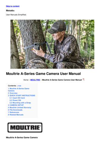
1. Overview1.1 Range of ApplicationThe network cameras with powerful image processing capacity may be applied at various public placessuch as mall, supermarket, school, factory and workshop, as well as in environments requiring HD videoimage such as bank and traffic control system, as shown below:MonitoringCenter4
1.2 Product DescriptionAn IP camera is a digital online surveillance camera embedded with Web server and capable ofindependent operation, giving user access to real-time monitoring through web browser or clientsoftware from any place across the world.IP camera is based on the latest Hisilicon solution, an integrated media processing platform foraudio/video acquisition, compression and network transmission on a single board. It is in compliancewith H.264/ H265 High Profile encoding standards. Any remote user can have access to real-timemonitoring by entering the IP address or domain name of the IP camera in web browser. This networkcamera solution is applicable to residential or business environmentas well as a wide range of situationsrequiring remote network video monitoring and transmission. The IP camera products are easy to installand operate.The IP cameras can be managed by several users with different authorization levels.IP cameras allows mobile detection, and sends e-mail and snapshot taken in case of emergency andstore the image or video snapshot in SD card for retrieval.1.3 Operation EnvironmentOperating system: Windows 7/Windows 8/Windows 2008 (32/64-bit),Windows 2003/Windows XP/Windows 2000 (32-bit)CPU: Intel Core Duo II dual-core processor or higherMemory: 1G or more Video memory: 256M or moreDisplay: 1024 768 or higher resolutionIE: IE 6.0 or higher version5
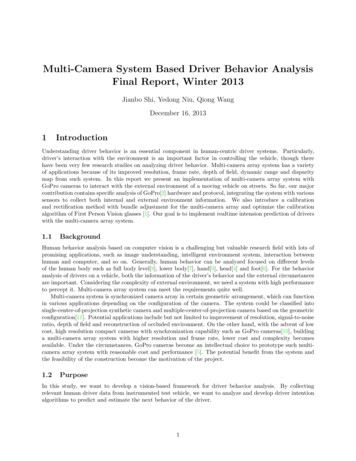
2. Device ConnectionIP camera can be connected in two ways:1. Connection to PCConnect IP camera to PC via straight-through network cable, with power input connected to a DC12V adaptor, and set the IP addresses of the PC and IP camera in one network segment. The IPcamera will communicate with PC within one minute after being powered on if the network operatesnormally.2. Connection to router/switchThis is more commonly used in connecting the IP camera to Internet, where the camera and PC areconnected to LAN ports of a router/switch, with gateway of the camera set to the IP address of therouter.6
3. Device Operation Instructions3.1 Check Connection1.The default factory IP address for IP camera is 192.168.1.168 and the subnet mask is255.255.255.0. Allocate to your computer an IP address in the same network segment as the IPcamera, for example, 192.168.1.69, and a same subnet mask as that of the IP camera.2.Test whether the IP camera is connected properly and started normally by clicking on Start Run and entering "cmd" and pressing ENTER, and entering "ping 192.168.1.168" in thecommand line window toCheck whether the IP camera is accessible. If the PING command is executed successfully, itindicates that the IP camera operates normally and the network is connected properly. If the PINGcommand fails, check IP address and gateway setting of the PC and connectivity of the network.7
3.2 Searching DeviceTips: IPC Device Search may be used for device searching across network segments. Beforerunning IPCDevice Search, click on the local connection iconat the lower right corner of the desktop;1. Add IP addresses of several network segments in TCP/IP setting for local connection (as shownbelow). By running the searching tool you can search any device with IP address in the samenetwork segment.Note:IPC Device Search uses multicast protocol for device searching across segments but any firewallforbids traffic of multicast data packets, so any firewall must be disabled in order that network theinformation on device can be acquired.8
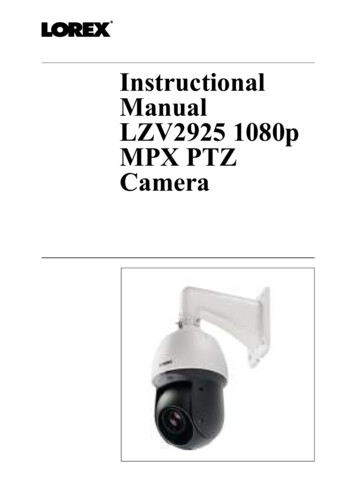
Online device searching procedure1. Run IPC Device Search by double clicking icon. It will search and display any online IPC andits IP address, port number, number of channels, device type and version, subnet mask, gateway,MAC address and connection pattern.9
Upgrade:it can offer 1pcs or more than 1pcs IP camera upgrade.Please choose the IP camera you wantto upgrade in the left frame,Open the icon to choose the software you want ,put in the user name andpassword, the press the right corner button to upgrade.Config: Double-click the selected camera in the search page, turn to the Config page to reboot thecamera, change passwords, and reset the camera.10
3.3 Installation of Controls and Login to SystemBefore using IE (Internet Explorer) browser to access the IP camera for the first time, related plug-incomponents must be installed by following the procedure below:Access IP address of the IP camera to automatically load the controls from it.In a pop-up plug-in installation dialog box, choose an installation option to perform the installationprocess.11
3.3.1 PreviewOperate IE and enter the IP address of the camera (http://192.168.1.168) to open a login box asshown below:12
In the login box you can choose a language for the IE client. Enter your user name (admin by default)and password (admin by default) and then press OK to open a preview frame as shown below:Some buttons in the preview frame are described below.: Color setting button, for setting of color, brightness, contrast, saturation and sharpness of theframe.:PTZ CONTROL press the icon ,then it show below picture::It has eight difference angle to control in the circle button,0-10,it means difference PTZspeed,ZOOM:adjust lens FOCUS: fix lens.Restore: restore factory setting .: read the recording file from SD card, and then playback from browser.13
: Access to device setting menu, for customized setting of various device parameters.: For setting of snapshot, video file type and storage path.: Help information (including current user, Web browser and plug-in versions), logout button,for returning to the login page.:Video preview switch enable/disable, original preview frame ratio,automatic preview frame ratio, full preview frame from the left to the right.: Preview control buttons - Zoon-In/Out, Open Video, Snap and SoundOn/Off, Mircophone arranged from the left to the right.: Dynamic switching of bit stream for the preview frame.Click Path Configuration button to pop up the following dialog box: In this dialog box you can set videostorage location, paths for download of remote file and storage of image snapshot, file type (RF bydefault, in H265 encoding) and video recording duration.3.3.2 Playback(optional function)Click record file to playback, select the corresponding date, then click the Search to go to below page14
User can search video by file type as needed, and operate the video through the simple tool on thetoolbar, e.g. open/stop video , bit stream video, recording, snapshot, download recording , quick motionvideo playback, Sound On/Off.15
4 Parameter Setting4.1 Display ConfigurationClick on Parameter Setting to open the page as below (preview setting page by default):Name of channel: name of the IP cameraDisplay of channel: Choose to display or conceal it.Time display: Choose to display or conceal it.Blinking control: Choose 50Hz, 60Hz or disable it.Transparency: Choose transparency of display of name of channel and time on the preview frame(smaller value indicates higher transparency)OSD: the text in red color on the frame; you can locate display of the name of channel and time bydragging it in the preview frame.16
17
4.2 Image ControlClick on Image Control in Display Configuration to open the following page:IR-Cut Model: Classified into GPIO Automatic, Colored, and Black-White models.Delay: IR-cut switching delay.Image Flip-Over:including flip horizontal, flip vertical, Corridor mode and Angle rotation (0 、180 )Image Control: backlight compensation, 3D noise reduction, WDR, automatic gain, shutter speed,exposure time and de-moist model.Note: Below 2MP device ,it doesn't support Corridor mode and Angle rotation , fog mode.18
4.3 Video BlockingClick on Video Blocking in Display Configuration to open the following page:Procedure of setting video blocking:1.Check Enable Video Blocking2.Press down and hold the left mouse button and drag out a area for video blocking (up to four areasat one time)3.Click on Save to enable the video blocking area.Remove: After clicking Refresh, choose a blocked area by clicking it and then click Remove and clickSave to remove it.19
4.4 ROI (if applicable)Click on ROI in Display Configuration to open the following page:Procedure of setting ROI:1.Choose an area of application2.Press down and hold the left mouse button and drag out a ROI area (only one ROI can be set foreach area)3.Click on Save to apply the ROI area.Bit stream type: Choose bit stream effective for ROI among Main Bit Stream, Sub-Bit Stream and CellPhone Stream.Area Numbering: Up to 8 ROI areas can be set in one bit stream.Enable ROI area: Enable or disable ROI areaArea image quality: Set quality of the image in the area (relative quality, absolute quality)ROI level: Set ROI level in one bit stream; larger value indicates higher-quality image in ROI area (1 6Levels)Non-ROI frame rate: Set frame rate out of RIO area; smaller value indicates higher-quality image in ROI20
area. Range of frame rate is in relation to video standard and resolution. (Note: Different non-ROI framerates may be allocated to different ROI areas, but the minimum value among them is used as the framerate to be applied for the non-ROI area on the preview frame. )5.Record Parameters5.1Rec ParametersClick Rec Parameters under the menu Record, go to below pageThis function is to control the record, pre record and record type (main stream and substream)5.2ScheduleClick Schedule under the menu Record, then go to the page as below21
As image: one grid in the table is 30 minutes, green is normal record, yellow is motion detection alarm, red is I/0User can setup according to private requirement to choose different record type and time。6. Network Parameters6.1 Network ParametersClick on Network Parameters in Network Parameter Menu to open the following page:22
Networking mode: DHCP (Automatically Acquired), Manually Configured and PPPOE; the default isManually ConfiguredMedia port: Media port for IPCWeb port: Web port for IPCIP address: IP address of IPCSubnet mast: Subnet mast of IPCDefault gateway: Default gateway of the devicePreferred/Alternate DNS server: Set DNS serverUPNP: Enable or disable UPNP function for the device (enabled by default)Note: To enable UPNP, the media/web/cell phone port should be set to a value between 1024-65535;the media port is used for connection of proprietary cell phone client; cell phone port is used forconnection of the mobile client.23
6.2 Bit stream settingClick on Bit Stream Setting in Network Parameter Menu to open the following page:By default the available bit streams are: main bit stream, sub-bit stream and cell phone bit steam.You can set resolution, frame rate, video encoding, encoding level, audio, I frame interval, variable framerate and bit stream size respectively for main bit stream, sub-bit stream and cell phone bit steam.Resolution: Set resolutions respectively for bit streams: The highest resolution for main bit stream is2048 1536. The higher resolution for sub-bit stream is 704 480. The only resolution available for cellphone bit steam is 320 480.Note: The higher resolution for main bit stream of 3MP Series is 2048*1536 (frame rate of 30 fps). Thehigher resolution for main bit stream of 4MP Series is 2592*1520 (frame rate of 20 fps). The higherresolution for main bit stream of 5MP Series is 2592*1944 (frame rate of 15 fps).The higher resolution formain bit stream of 8MP Series is 3840x2160 (frame rate of 30 fps). The higher resolution for main bitstream of 2MP Series is 1920*1080 (frame rate of 30 fps).Frame rate: When refresh rate is 50Hz, the maximum available frame rate is 25 fps. When refresh rateis 60Hz, the maximum available frame rate is 30 fps.Video encoding: Set video encoding (H265/H264) for each bit stream.Audio: Enable audio for each bit stream.I frame interval: Set I frame interval.Bitrate control: Set constant or variable bitrate for bit stream.24
Bit stream: Set bit stream value by choosing fixed value or customizing it.Note: Range of main bit stream is 256-8192.Range of sub-bit stream is 128-4096.Range of cell phone bit steam is 8-1536.Video encoding and encoding level are unavailable in setting page of IP camera of 2MP Series.6.3 E-Mail ConfigurationClick on E-Mail Configuration in Network Parameter menu to open the following page:E-Mail Configuration: mail service setting - used with alarm function to upload images snapped to themail server.25
Enable e-mail: Enable or disable e-mail function.SSL:ON/OFF SSL proto.Port: The default port number is 25 (mail serve port).SMTP server: Enter the address of mail server.Address of sender: Address of sending mailbox.Password of sender: Password of sending mailbox.Address of recipient: Address of receiving mailbox.Time interval: Time interval for sending mail (1 minute, 3 minute, 5 minute, 10 minute).E-mail test: Click it to test whether the mailbox is configured properly by sending a test mail tothe recipient's mailbox.26
6.4 DDNS ConfigurationClick on DDNS Configuration in Network Parameter menu to open the following page:DDNS configuration: Dynamic DNS configuration - used with server for access from an extranet.Enable DDNS: Enable or disable it.Address of server: Choose "3322".Name of host: Enter the name of active serverUser name: Name of the userPassword: Password of the user27
6.5 IP FilteringClick on IP Filtering in Network Parameter menu to open the following page:Filtering mode: Three modes are available (Allow all IP connections, Allow all IP connections as set,Forbid IP connection as set).Add: Add any allowed or forbidden IP addressDelete: Delete any IP address added previously6.6 RTSPClick on RTSP in Network Parameter menu to open the following page:28
RTSP Enabling: Enable or disable RTSP. RTSP is enabled by default. After it is disabled, it will not befound with ONVIF.29
RTSP Port: The default port number is 554, and can be changed to another value between 1024 and65535. Modification to the parameter will restart the system.Operation Instructions:For IP cameras of 3MP/4MP/5MP/8MP Series: rtsp://IP:Port/ch00/A A:0 (main bit stream), 1(sub-bitstream), 2 (cell phone bit stream)For IP cameras of 2MP Series: rtsp://IP:Port /AA:0 (main bit stream), 1(sub-bit stream), 2 (cell phonebit stream)6.7 FTPClick on FTP in Network Parameter menu to open the following page:FTP: FTP service setting - used with alarm function to upload images or videos snapped to the FTPserver.FTP:Enable or disable it.User name:The user name for access to FTP servicePassword:The password for access to FTP service30
FTP Server: Enter the address of FTP server.Port:FTP service port number; the default number is 21.Transmit Image: Check it to transmit image7. Alarm Parameter7.1 Mobile DetectionClick on Mobile Detection in Alarm Parameter menu to open the following page:Procedure of setting Mobile Detection:1.Check Enable Mobile Detection.2.Press down and hold the left mouse button and drag out an area for mobile detection.3.Set the sensitivity for mobile detection (ranging from 1 to 8; larger value indicates higher sensitivity).4.Used with SMTP to enable mail delivery.5.Click on Save to apply the settings.(Note: When any object moves within the target area, a letter "M" in green color will be displayed on the31
preview frame)32
7.2 I/O Alarm (if applicable)Click on I/O Alarm in Alarm Parameter menu to open the following page:I/O Alarm Input: Enable or disable I/O alarm.I/O Alarm Output Time: Set I/O alarm output time (10s, 20s, 40s, 60s)Recording Delay Time: After checking Enable Triggered Recording, you can set recording delay time(5S/10S/20S/30S)7.3 Lens BlockingClick on Lens Blocking in Alarm Parameter menu to open the following page:Check Lens Blocking option (checked by default) to activate Security Level and Mail Linkage options.33
Security Level: Set security level for lens blocking (Level 1 8; larger value indicates higher securitylevel)Mail Linkage: It is disabled by default. After enabled, it may be used with SMTP to enable mail delivery.8. DeviceIt includes SD Card(optional function) Logs and Audio. Their interfaces and functions aredescribed below.8.1 SD Card(optional function)Click SD Card under the menu Device, then go to below pageInsert SD card to device, system will auto detect the total capacity and balance capacity of SD cardand giveThe information of time to recordSD Card Overwrite:when the capacity of SD card is 0, new recorad will overlap previous record(thisfunction is default on)SD Card Format: to format SD card34
8.2 AudioClick on Audio in Device menu to open the following page:Procedure of setting Audio:Check Open Audio option to access audio setting, and set audio input/output volume (ranging 0 10),and then click on Save to save the parameters set.(Note: For application of audio function, the audio option in Bit Stream Setting needs to be enabled)8.3 LogsClick on Logs in Device menu to open the following page:35
Log Type: Eight types of logs are available - system logs, network logs, parameter logs, alarm logs,user logs, recording logs, storage logs and all logs). Choose the starting and ending date/time forretrieval.Click on "Search" to retrieve and display related logs in the table below.Click on "Delete" to delete all device logs.Click on "Refresh" to refresh the logs selected.9. System ParametersSystem parameters include Basic Information, User Configuration and System Information. Theirinterfaces and functions are described below.9.1 Basic InformationClick on Basic Information in System Parameters menu to open the following page:36
The device time, system time, date format and time format contained in the basic information can bemanually set and saved.Three automatic time correction functions are provided in this device.37
DST: Check Daylight Savings Time (DST) option to enable DSTcorrection.The device will correct the time based on the time deviation as set.NTP: Check Enable NTP option, input the address of time serverand choose a time zone and then save the setting. The system willcorrect time in accordance with the time server.Sync with PC Time: The device will use PC as a time server tocorrect time.9.2 User ConfigurationClick on User Configuration in System Parameters menu to open the following page:Here you can set user access authority and login password.38
9.3 System InformationClick on System Information in System Parameters menu to open the following page:Here some system information on the device will be displayed, including device type, MAC address andsoftware version.You can visit mobile app through P2P QR code directly。39
10. AdvancedIt includes System Update, Default Parameters and System Maintenance. Their interfaces andfunctions are described below.10.1 System UpdateClick on System Update in Advanced menu to open the following page:Update will be unavailable if the update files do not match the target device.10.2 Default ParametersClick on Default Parameters in Advanced menu to open the following page:40
Check relevant options and click on Save to recover the default factory settings for the options aschecked.10.3 System MaintenanceClick on System Maintenance in Advanced menu to open the following page: 、Here you can set regular restart or manual restart of the device.41
11. Intelligent11.1 Smart Scheduleone grid in the table is 30 minute,User can setup according to private requirement to choose differentrecord type and time。42
11.2 Smart AnalysisThis page can correctly show the different time period’s line crossing count ( including different years , monthsand weeks’ line crossing count). User can search the video according to the recording types, alarm types andthe beginning time of the recording.11.3 Perimeter Intrusion Detection(PID)Click Perimeter Intrusiion under the menu Intelligent:Function description: in the preview page, to detect and follow up the invaded objectSwitch:PID function master switch43
Latch Time:when trigger alarm, the external alarm device ouput alarm time, can selected time period is5S,10S, 20S, 30S
IP camera can be connected in two ways: 1. Connection to PC Connect IP camera to PC via straight-through network cable, with power input connected to a DC 12V adaptor, and set the IP addresses of the PC and IP camera in one network segment. The IP camera will communicate with PC within one minute after being powered on if the network operates