Transcription
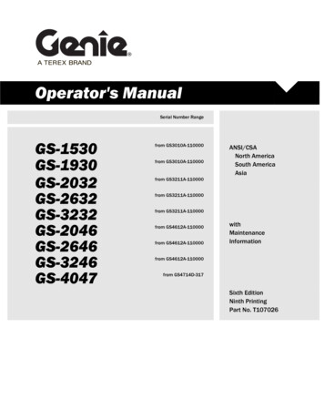
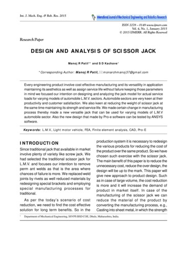
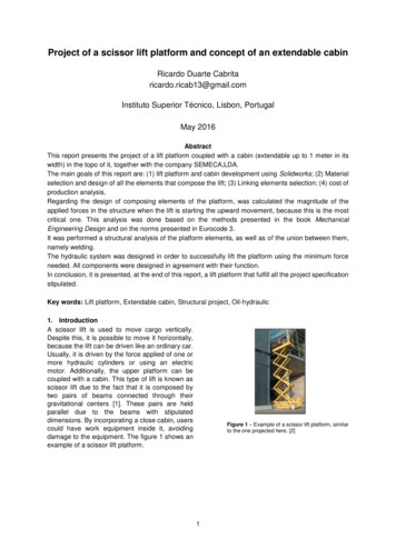
Project of a scissor lift platform and concept of an extendable cabinRicardo Duarte Cabritaricardo.ricab13@gmail.comInstituto Superior Técnico, Lisbon, PortugalMay 2016AbstractThis report presents the project of a lift platform coupled with a cabin (extendable up to 1 meter in itswidth) in the topo of it, together with the company SEMECA,LDA.The main goals of this report are: (1) lift platform and cabin development using Solidworks; (2) Materialselection and design of all the elements that compose the lift; (3) Linking elements selection; (4) cost ofproduction analysis.Regarding the design of composing elements of the platform, was calculated the magnitude of theapplied forces in the structure when the lift is starting the upward movement, because this is the mostcritical one. This analysis was done based on the methods presented in the book MechanicalEngineering Design and on the norms presented in Eurocode 3.It was performed a structural analysis of the platform elements, as well as of the union between them,namely welding.The hydraulic system was designed in order to successfully lift the platform using the minimum forceneeded. All components were designed in agreement with their function.In conclusion, it is presented, at the end of this report, a lift platform that fulfill all the project specificationstipulated.Key words: Lift platform, Extendable cabin, Structural project, Oil-hydraulic1. IntroductionA scissor lift is used to move cargo vertically.Despite this, it is possible to move it horizontally,because the lift can be driven like an ordinary car.Usually, it is driven by the force applied of one ormore hydraulic cylinders or using an electricmotor. Additionally, the upper platform can becoupled with a cabin. This type of lift is known asscissor lift due to the fact that it is composed bytwo pairs of beams connected through theirgravitational centers [1]. These pairs are heldparallel due to the beams with stipulateddimensions. By incorporating a close cabin, userscould have work equipment inside it, avoidingdamage to the equipment. The figure 1 shows anexample of a scissor lift platform.Figure 1 – Example of a scissor lift platform, similarto the one projected here. [2]1
The lift projected will have 3 scissor “pairs”.The lift is symmetric, so it will have 6 scissor“pairs” (for comparison, the lift in figure 1 has4 “pairs”). It will be coupled with anextendable cabin. The cabin’s width isvariable from 2.5 meters to 3.5 meters but itslength is fixed in 5 meters. It is driven by theforce applied of two hydraulic cylinders, partof the hydraulic system. This system isresponsible for the ascent and descentmovement of the lift.3. Norms and legislationThe lift platform is a structure mostlycomposed by steel, and, due to that fact itshould be in accordance with the norms andlegislation of the European Union, so that, atthe end, it can be assumed that is safe toproduce and use that same system. It will beused the norm NP EN 1993 – Eurocode 3:Design of steel structures [3]. To thestructural steel, Eurocode 3 define thefollowing material properties:ooo2. Project specifications2.1 Project requisites1) The platform should support 4000kg.This value already includes the weight ofthe cabin and the cargo/users.2) The platform should go down completelyand reach 6 meters in height.3) The cabin’s width must be, at most, 2.5meters when closed.4) Itshouldbeusednormalizedcomponents.5) The cabin should have 1.8 meters inheight.6) The cabin should be extendable, inwidth, from 2.5 up to 3.5 meters.7) The lift should have manual controls tocontrol the ascent and descent of the liftand to open and close the cabin.8) The cabin should have a stop systemwhen it reaches 6 meters and thebottom.9)The lift should be projected basedon norms and codes in force.Modulus of elasticity (E 210 𝐺𝑃𝑎)Poisson’s ratio (𝜈 0.3)Shear Modulus𝐺 𝐸2(1 𝜈) 81 𝐺𝑃𝑎3.1 Stress calculation in transversalsections of structural elementsTo calculate the equivalent stress in atransversal section of a component,Eurocode 3 states that can be used theequivalent stress of von Mises, given by:𝜎𝑉.𝑀. 𝜎 2 3𝜏 2Note: σ represents the resultant of normalstress applied in that section andτrepresents the resultant of shear stressapplied in that section. [3]3.2 Stress calculation in welded jointsRegarding welded joints, it will be used themethod presented in the book MechanicalEngineering Design. [4]3.2.1 Stress in Welded Joints in TorsionIn the figure 2, it is represented a beamsupported by two fillet welds. At the end ofthe beam it is applied a force F. This forcewill create two different types of stress in theweld: a primary shear and secondary shearor torsion.2.2 Project constrains1) The costs ofproductionsandassembling the lift should be lower than12 000 .2) It should be used materials thatSEMECA, LDA is familiarized.3) It should be used processes thatSEMECA, LDA is familiarized (like MIGwelding).The primary shear in the welds is given by:𝑉𝜏′ 𝐴where A represents the throat area of all thewelds and V is the shear force. Thesecondary shear in the welds is given by:2
𝑀𝑟𝐽where r is the distance from the centroid ofthe weld group to the point in the weld ofinterest (critical point), J is the second polarmoment of area of the weld group and M isthe torsion moment.The width of the welds are going to beconsidered equal to 1, being treated likelines and not like areas. The advantage oftreating the weld size as a line is that thevalue of JU is the same regardless of theweld size. As the width of a fillet weld is0.707h, J can be related to JU:𝐽 0.707ℎ𝐽𝑢moment of area of the weld group and M isthe bending moment.Considering the welds as lines, like in theprevious section, I can be related to IU:𝐼 0.707ℎ𝐼𝑢𝜏 ′′ 4. MethodologyThe project was divided in 5 parts:1. Lift platform modeling and structuralproject2. Hydraulic system project3. Lift platform assembling4. Cost estimation to perform the 3previous points5. Extendable cabin modeling and function4.1 Lift final structureThe solution found for the lift structure ispresented in the figure 4. In the same figureis indicated the structure most importantparts.Figure 2 - Beam subject to a torsion moment. [4]Superiorplatform3.2.2 Stresses in Welded Joints inBendingIn the figure 3, it is represented a beamsupported by two fillet welds. At the end ofthe beam it is applied a force F. This forcewill create two different types of stress in theweld: a primary shear and secondary shearor ylindersInferiorplatformBigplatformFigure 4 – Scissor lift structureFigure 3 - Beam subject to a bending moment. [4]The primary shear in the welds is given by:𝑉𝜏′ 𝐴A represents the area of the welding throat.The primary shear in the welds is given by:𝑀𝑐𝜏 ′′ 𝐼where c is the distance from the centroid ofthe weld group to the point in the weld ofinterest (critical point), I is the secondCharacteristics: Weight (without cabin nor cargo): 3500kg Width: 2.5 meters Length: 9 meters Height that the superior platform shouldreach: 6 meters Maximum allowed weight (cabin cargo/users): 4000 kg The beams that form the “scissors” arejoined by pins. Each beam has 33
connections (one in each extremity andone in the center)4.3 Hydraulic systemThe hydraulic system (figure 7) will beresponsible for:1. Lift the platform up to the required height(6 m), through the hydraulic system andlower it in a controlled way.2. Control the telescopic cylinders in orderto fix the lift to the ground.Superior platform characteristics: Maximum width: 2.5 metersMaximum length: 5 meters4.2 Extendable cabin structureThe solution found for the extendable cabinis presented in the figures 5 and 6. As statedbefore, this cabin can change its width from2.5 up to 3.5 meters.4.4 Total costs4.4.1 Labor CostsIt will be necessary the work of 2 employeesfor 2 months to produce and assemble thelift. Approximately, it is 368 man-hours. Thecost of each man-hour is 7 , so it sums up in5152 .4.4.2 Material costsDue to the fact that almost every part of thestructure is composed by steel, it will beassumed as if all structure were composedby steel. Steel’s price is around 1 per kg(actually it is less, but it will be consideredthis price because not all the parts arecomposed by steel). The total material costis approximately 3500 . In weldingconsumable and gas it will be spentapproximately 300 .Figure 5 - Extendable cabin structure (opened)Cabin characteristics:4.4.3 Hydraulic system costsIn the figure 7, it is represented the hydraulicsystem, containing all its components. Thetotal cost of the hydraulic systemcomponents is 1639 , without consideringthe hydraulic cylinders because they wereconsidered in the material costs. 4.4.4 Total costsHaving into account the costs presentedpreviously come to a final value of 10591 like its presented in the table 1.Figure 6 - Cabin completed with all its componentsWeight: 2300 kgVariable width: 2.5 up to 3.5 metersLength: 5 metersWalls move due to a rack-and-pinionsystem placed below the cabin. The superior part of the walls have aninclination of 45 and the inferior part isvertical. One of the fixed walls will have a door.ValorLabor5152 Material3 500 Welding consumable 300 Hydraulic system1639 Total10 591 Table 1 - Total costs4
Figure 7 - Hydraulic system and its components5. Structural design5.1 Lift platform elementsIn the figures 8, 9, 10 and 11 arerepresented the lift most importantelements.10115896722121234Figure 10 - Superior Platform and its componentsFigure 8 - Lateral view of the lift1920182114152516131723Figure 9 - Inferior part of the liftFigure 11 - Detailed view of some elements524
In the table 2 is represented the materialsthat compose each element and thecorresponding yield strength.ElementsMaterial(steel)Yieldstrength (σy)2S235JR235345,6,7,89,1011S235JRS235JRS 235 JRS 235 JRS 235 ,16place a big weight in a small area. In thefigure 12 it is represented the distributedload that is going to be considered.Figure 12 – Distributed load(hardened and 370tempered)AISI 4320H515S 235 JR2355.3.1 Forces applied in Element 1In order to perform the structural analysis, itwill be firstly estimated the force that thehydraulic cylinders will have to apply to liftthe platform. It will be considered an equaldistributed point through 4 support points inthe superior platform. The total load is 5000kg, as stated before and, consequently, theload applied in each point is 1250 kg. Thisforce is represented as W. It will becalculated the forces applied in elements 1and 2 because are these elements that arethe most critical ones. In the figure 13 arerepresented the forces applied in theelement 1. Fm is the force applied by thehydraulic cylinder, Fmy and Fmx are thecomponents of Fm. Ry and Rx are thereactions due to connections with otherelements. ϴm is the slope the cylinders makewith the horizontal.Table 2 - Elements' material and its yield strength. [5][6] [7]5.2 Loadings and simplificationsThe lift has the function of, not only supportthe cabin and cargo’s weight but also elevateit from the bottom up to 6 meters. The cabinwill be under different forces with differentorientations. The maximum projected weightthat the platform should lift is 5000 kg, whereit is already applied a safety factor of 1.25. Inother words, the maximum allowed weight,in use, is 4000 kg, comprehending the cabinand cargo.5.3 Applied forces calculationIn this section, it will be studied the amountof stress that elements are under when thehydraulic cylinders are at the minimum slope(in the beginning of the ascent). This is themost critical moment because the verticalforce applied by the hydraulic cylinders isvery low due to the low slope. Consequently,the cylinders will have to apply a highamount of force.Weight distribution in the superior platformmay not be always uniform. However, thisdifference should not be significant becausethe users will be previously warned to avoidDECϴmFigure 13 – Applied forces in the Element 16
5.3.2 Forces applied in Element 2Element 2 is the beam that is connectedthrough their centers (point E) with theelement 1. The forces Fx and Fy are theforces that the element 1 apply in element 2and vice-versa. ϴm is the slope the element2 makes with the horizontal.each element. In this paper it is going to bestudied the two most critical elements of thelift, element 1 and 12.Each element will be analyzed based on theEurocode 3. This code states the von Misesstress has to be smaller than its yieldstrength in every point of the element:𝜎𝑉.𝑀. 𝜎 2 3(𝜏𝑉 2 𝜏 𝑇 2 ) 𝜎𝑌where:𝜎 𝜎𝑀 2 𝜎𝑁 2A5.4.1 Element 1In the figure 15 it is represented the section’sspecifications and dimensions. In the figure16 it is represented the free-body diagramregarding element 1.EϴRx1BFigure 14 - Applied forces in the element 2IXX 2444 x 10-8 m4IYY 818 x 10-8 m4A 52.60 cm2Based on the forces applied in the elements1 and two, were defined 6 static equations.However, existed 7 variables: (Fx, Fy, Ry1,Rx1, Ry2, Rx2 e Fm), which leaded toundetermined equations. In order tocalculate the values of each variable, thevalue of Fm was varied until Ry2 wasnegative, which indicated the platform wasmoving upwards. The value of each variablewas:Fm 190066,4 NFX 171768,4 NFY 20477,05 NRX1 171768,4 NRY1 8214,554 NRX2 15311,71 NRY2 -820,347 NFigure 15 - Section specification and dimensions ofelement 134V [N]36777.312259.1120-1181.9M [N.m]41096.60Each cylinder has to apply a total force of190066.4 N, around 19 tons of force. Thecylinders will have to apply this amount offorce, only, in the moment when the lift isstarting its ascent because it is, in thatmoment, that the cylinders have the lowerslope.-559.45N [N]152882890-1709495.4 Resistance analysis of elements 1and 12After determine the values of each appliedforce in the elements 1 and 2 it is necessaryto do an analysis regarding the
The lift projected will have 3 scissor “pairs”. The lift is symmetric, so it will have 6 scissor “pairs” (for comparison, the lift in figure 1 has 4 “pairs”). It will be coupled with an extendable cabin. The cabin’s width is variable from 2.5 meters to 3.5 meters but its length is fixed in 5 meters. It is driven by the force applied of two hydraulic cylinders, part