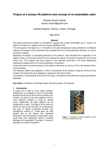
Transcription
K ILCOPY04NCN4Technical Document 1550June 1989Mathematical Analysis ofScissor LiftsH. M. SpackmanApproved for pubic release; distribution Is unlimited.k04IL
NAVAL OCEAN SYSTEMS CENTERSan Diego, California 92152-5000R. M. HILLYERTechnical DirectorE. G. SCHWEIZER, CAPT, USNCommanderADMINISTRATIVE INFORMATIONThis work was performed for the U.S. Marine Corps, Development/EducationCommand, Quantico, VA 22134, under program element number 0603635M and agencyaccession number DN308 274. The work was performed by the Advanced Technology Development Branch, Code 612, Naval Ocean Systems Center, San Diego, CA 92152-5000.Released byR. E. Glass, HeadAdvanced TechnologyDevelopment BranchUnder authority ofD. W. Murphy, HeadAdvanced SystemsDivisionFS
UNCLASSIFIEDSECURITY CLASSIFICATION OF THIS PAGEREPORT DOCUMENTATION PAGEIa. REPORT SECURITY CLASSIFICATIONlb. RESTRICTIVE MARKINGSUNCLASSIFIED3. DISTRIBUTION/AVALABLITY OF REPORT2a. SECURITY CLASSIFICATION AUTHORITY2b. DECLASSIFICATION/DOWNGRADING SCHEDULEApproved for public release; distribution is unlimited.5. MONITORING ORGANIZATION REPORT NUMBER(S)4. PERFORMING ORGANIZATION REPORT NUMBER(S)NOSC TD 15506b. OFFICE SYMBOL 7a. NAME OF MONITORING ORGANIZATIONLCode 612Sa. NAME OF PERFORMING ORGANIZATIONNaval Ocean Systems Center7b. ADDRESS IV4, %.aWZC)Se. ADDRESS ft. SAhaWZCv)San Diego, California 92152-50008a. NAME OF FUNIN/SPONSORNG ORGANIZATION 8b. OFFICE SYMBOL 9. PROCUREMENT INSTRUMENT IDENTIFICATION NUMBERU.S. MarineCorpsI10. SOURCE OF FUNDING NUMBERSPROGRAM ELEMENT NO. PROJECT NO.BC, ADDRESS ft &i%6aW2dCod.)DevelopmentlEducation CommandQuantico, VA 2213411. TITLE (S0603635MTASK NO.AGENCYACCESSION NO.CH58DN308 274)Mathematical Analysis of Scissor Lifts12. PERSONAL AUTHOR(S)H. M. Spackman13a. TYPE OF REPORT13b. TIME COVEREDFinal16. SUPPLEMENTARY NOTATIONFROM17. COSATI CODESFIELD15. PAGE COUNT6318. SUBJECT TERMS (Culmmulnmmsfld. A/'hbtathv)GROUPSUB-GROUP. .-.h .19. ABSTRACT (14. DATE OF REPORT (Var, UwA D')June 1989TO.Sactuatois l- .umuij'm/,it-ew'.C",' ,l/',.P.[i:,)This document presents mathematical techniques for analyzing reaction forces in scissor lifts. It also presents several design issuesincluding actuator placement, member cross-section, and rigidity.,20. OISTRIBUTION/AVALABUTY OF ABSTRACT[]UNCLA88IFEDUNUMOTED21. ABSTRACT SECL4ITY CLASSIFICATIONE] SAME AS RPT22&. NAME OF RESPONSIBLE INOIDUALH. M. SpackmanDD FORM 1473, 84 JANE]DTIC USERSUNCLASSIFIED22b. TELEPHONE (iwkfAw0**)(619) 553-411083 APR EDITION MAY E USED UNTILEEXHAUSTEDALL OTHER EDITIONS ARE OBSOLETE22c. OFFICE SYMBOLCode 612UNCLASSIFIEDSECURITY CLASSIFICATION OF THIS PAGE
UNCLASSIFIEDSEOURITY CLA88FICATtON OF TMlPAGEDD FORM 1473, 84 JAN(whmawDi iu)UNCLASSIFIEDSECURIY CLASSCATION OF THS PAGE (WftDdlr&*md)
CONTENTS1.0IN T R O D U CT IO N .2.0N O M E N C LA T U R E .I3.0GENERAL SCISSOR LIFT EQUATIONS .3.1. Equations for the Basic Scissor Structure .3.1.1 Load 1: Centered Load in the Negative y Direction .43.2.1553.1.23.1.3Load 2: Moment About the z Axis .Load 3: Centered Horizontal Load in the Positive x Direction .9123.1.4Load 4: Centered Load in the Positive z Direction .193.1.5Load 5: Moment About the x Axis .243.1.6Load 6: Moment About the y Axis .26Equations for the A ctuator . .3.2.1 Derivation of dh/df Assuming Both Actuator Ends arePinned to a Scissor M em ber .30353.2.2 Derivation of dh/df Assuming One Actuator End isP inned to G round .394.0CALCULATION OF REACTION FORCES .455.0ACTUATOR PLACEMENT .476.0STRENGTH AND RIGIDITY .537.0CO N C L U S IO N .568.0BIB L IO G R A P H Y .56FIGURES1.2.3.4.5.6.7.8.9.Nomenclature: applied loads and scissor lift dimensions .Nomenclature: reaction forces .Scissor lift m odels .Basic scissor structure with load applied in the negative y direction .Freebody diagrams for load applied in the negative y direction .Basic scissor structure with a moment about the z axis .Freebody diagrams for applied moment about the z axis .Basic scissor structure with load applied in the positive x direct;ci .Freebody diagrams for load applied in x direction withthe back joints pinned . . .i234770101313
FIGURES (continued)10.II.12.13.14.15.16.17.1819 .20.21.22.23.24.25.26.27.Freebody diagrams for load applied in x direction withthe front joints pinned . . .Basic scissor structure with load applied in the positive z direction .Deflections and reaction forces for load applied in the positive z direction .Freebody diagrams for load applied in the positive z direction .Basic scissor structure with applied moment about the x axis .Freebody diagrams for an applied moment about the x axis .Basic scissor structure with applied moment about the y axis .Freebody diagrams for an applied moment about the y axis .Four level lift loaded in the x and y directions .U n ifo rm m ass .n-level lift with actuators attached between the bottom joints .C oordinates of a point on the lift .Path traveled by a point on a positively sloping scissor member .Length of an actuator attached between two points on a lift .Actuator position and displacement nomenclature .A ctuato r m od els .D etailed n-level scissor lift .P ossible actuator locations .dh28.29.30.31.32 .172020222525272731313335363840434647vsq-. 49Weightless n-level lift with actuator between left joints of level i .N orm al and tangential forces . .Sum m ary of reaction forces . .C ro ssb ra cing .49525455TABLEI.Comparison of dh/df for several actuator locations .Acc:6; 9 nn ForA.lr,: p:, ;-'-Codes48
1.0 INTRODUCTIONThe purpose of this document is to present mathematical equations for analyzingreaction forces in scissor lifts and to discuss several design issues including actuator placement, and strength and rigidity. In section 2.0 the nomenclature is presented. In section 3.1equations are derived for the scissor members whose reaction forces are not affected by theactuators. In section 3.2, equations for calulating the actuator forces directly are given. Insection 4.0 the equations from sections 3.1 and 3.2 are combined into a single method ofdetermining the reaction forces throughout the lift. Forces obtained from this analysis canbe used in selecting the appropriate material and cross-section of the scissor members, andto select suitable actuators. In the remaining sections the design issues listed above arediscussed.2.0 NOMENCLATUREFigure 1 shows an n-level scissor lift with the six possible applied loads. The letterH is used instead of F for the linear forces in order to avoid confusion with later terminology. Notice that H. and H, act in the positive x and z directions, respectively, whileHy acts in the negative y direction. The direction of H . was selected to correspond withloads normally encountered. At each joint there are also six possible reaction forces andmoments. In order to distinguish between joints, the nomenclature shown in figure 2 willbe used. The subscripts L, R, F, B, and M are used to denote left, right, front, back andmiddle, respectively. This system of subscripting was selected because the reaction forcesare usually symmetric allowing some of the subscripts to be dropped. One slight inconsistency in this nomenclature is the M subscript. All other subscripts come in pairs, ane ,obe totally consistent one more subscript could have been included to denote bottom. Thereasons for omitting this subscript are that symmetry never exists between the bottom andmiddle joints, and the bottom joints already have an excessive number of subscripts. Thereare cases in the paper where the L, R, F, and B subscripts are all dropped from the reactionforces at the bottom of the scissor resulting in X i , Yi, or Z i . The reader may mistakenlyassume that the equations for X i , Yi, and Z i also apply to the middle joints. This is nottrue. X i, Yi, and Z i apply only to the bottom joints. The M subscript is never dropped.Notice that the reaction forces at the top of the i and i-I scissors are not shown infigure 2. These forces are omitted because they are equal and opposite the forces at thebottom of the previous scissor, and therefore are not unique. Also notice that none of thepossible reaction moments at the joints are shown. The moment about the z axis is omittedbecause the joints are assumed to be frictionless. The reason this assumption is possible isbecause the radius through which the friction forces act is small and, if the joints are lubricated, the coefficient of friction is small. The reaction moments about the x and y axis' arezero for loads applied in the x-y plane. These loads include H. H', and M. It is believedthat they are also negligible for the out-of-plane loads Mr, M, and H. especially if crossbracing is used.
yIHyMYpinszslides/rollersx-level 1level 2hLeftlevel ndBack-oFront* wRight I-uFigure 1. Nomenclature: applied loads and scissor lift dimensions.
Detail AB-See detailA for loadsi-iXBU-1MRi-1YF-ZU-'ML'-M-IFi1ZU1X -i-XB i-1XF i-1ZMRi-1ZBR1ZFRi-1See detailB for loadsYMUMRiYFYFIYZBRi%L-FZF-XMiXFUZMRIZFRiDetail BZBUXBUReactionX-ForceY-ForceZ-ForceMUiiForcein pos. x dirin pos. y dirin pos. z e 2. Nomenclature: reaction forces.3Level1 thru nXMLI
3.0 GENERAL SCISSOR LIFT EQUATIONSAn n-level scissor lift with a single actuator in the i and i l levels is shown in figure3a. One possible way of calculating the reaction forces throughout the lift is to begin atthe top of the lift where the applied loads are known, and, using equations of static equilibrium, solve for the reaction forces in the first scissor (level 1). The forces at the top of thesecond scissor are now known since they are equal and opposite the forces at the bottom oflevel 1, and the forces in the second level can now be calculated. This process continues tolevel i. At this level there are more unknowns than equations because the actuator adds anunknown variable. The analysis now shifts to the bottom of the lift. The reaction forces atthe bottom of the lift can be found by doing a freebody analysis of the entire lift. Once theforces at the bottom of the lift are known, the reaction forces from level n to the bottom oflevel i l can be calculated. Now that the forces are known at the top of level i and at thebottom of level i 1, the remaining reaction forces can be determined using equations ofstatic equilibrium.level121n2n-Xa.modelleveloriginallift levellevelb.Figure 3. Scissor lift models.4i 21-i 11Xc.
This method of solution is almost impossible to do by hand because any error willbe carried on to later calculations. Also the number of calculations is overwhelming. It istherefore desirable to find a simpler method of analysis. Before developing this alternatemethod, two critical observations about the lift are necessary. First, notice that the reactionforces in levels i through i-I and in levels i 2 through n are completely unaffected by theplacement of the actuator as long as it is confined within the i and i l levels. In fact, thescissor members in levels 1 through i-I can be modeled as a scissor structure that has noactuators and is pinned to "ground" at all four bottom joints as shown in figure 3b. Thisstructure will be referred to as "the basic scissor structure" throughout this paper. Thisthought process can be continued by considering levels i 2 through n. Notice that thesemembers meet the criteria of a basic scissor structure except that the structure is upsidedown. This portion of the lift can therefore be modeled as the basic scissor structure shownin figure 3c. In this model the lift will have negative weight. The loads at the top of thismodel are easily determined by doing a freebody analysis on the entire lift. The second critical observation is that if frictional losses are assumed to be negligible, then the principle ofconservation of energy applies. This allows the actuator forces to be calculated directly.I
3.0 GENERAL SCISSOR LIFT EQUATIONS An n-level scissor lift with a single actuator in the i and i l levels is shown in figure 3a. One possible way of calculating the reaction forces throughout the lift is to begin at the top of the lift where the applied loads are known, and, using equations of static equilib-