Transcription
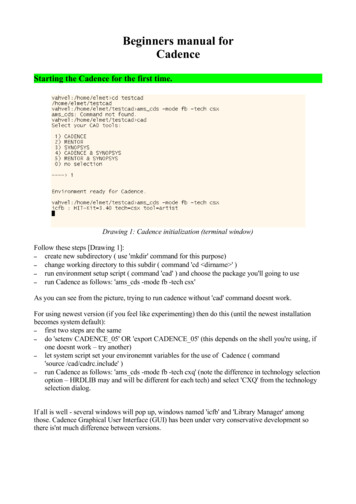
Beginners manual forCadenceStarting the Cadence for the first time.Drawing 1: Cadence initialization (terminal window)Follow these steps [Drawing 1]:– create new subdirectory ( use 'mkdir' command for this purpose)– change working directory to this subdir ( command 'cd dirname ' )– run environment setup script ( command 'cad' ) and choose the package you'll going to use– run Cadence as follows: 'ams cds -mode fb -tech csx'As you can see from the picture, trying to run cadence without 'cad' command doesnt work.For using newest version (if you feel like experimenting) then do this (until the newest installationbecomes system default):– first two steps are the same– do 'setenv CADENCE 05' OR 'export CADENCE 05' (this depends on the shell you're using, ifone doesnt work – try another)– let system script set your environemnt variables for the use of Cadence ( command'source /cad/cadrc.include' )– run Cadence as follows: 'ams cds -mode fb -tech cxq' (note the difference in technology selectionoption – HRDLIB may and will be different for each tech) and select 'CXQ' from the technologyselection dialog.If all is well - several windows will pop up, windows named 'icfb' and 'Library Manager' amongthose. Cadence Graphical User Interface (GUI) has been under very conservative development sothere is'nt much difference between versions.
Starting to work on new circuitYou'll probably have to create new library (for storing circuit modules) and at least one cellview(selected circuit module). Follow these steps:–create new library using 'Library Manager' window [Drawing 2]Drawing 2: Library manager - new library
–define new library name and choose techfile [Drawing 3, Drawing 4, Drawing 5]Drawing 3: Create new libraryDrawing 4: Technology selection, step 1Drawing 5: Technology selection, step 2Choose appropriate technology, TECH CSI or cdsDefTechLib.
–create new cell view (open menu on the Library Manager window and enter cell name, as seen on[Drawing 6, Drawing 7]Drawing 6: Creating new cellview, step 1Drawing 7: Creating new cellview, step 2
After this, circuit editor window appears [Drawing 8]. You can now start working on your design.Preferred work order should be following:Drawing 8: Editor window–place instances [Drawing 9], instances should all stem from library 'HRDLIB'. Keyboard shortcutfor this is 'i'.Drawing 9: Instances
–place I/O pins. These pins could be single wires or buses. Bus notation is written as'pin name start index:end index '. See [Drawing 10].Drawing 10: Adding pinsDirection field determines signal direction. Menu shorcut 'p'.
–create connections [Drawing 11] Note there are thin and thick wires (single signals and buses).For separating single signal or group of signals from bus, the wires have to have names. Thissolves the problem what signal should go where.Drawing 11: Wires and names
–finished circuit [Drawing 12]. Check and save it before doing any further operations.Drawing 12: Finished circuitNow there are several possibilities. You can use this circuit as building block for even more complexcircuit (as macro), run simulation in Cadence or export it for external tools like Turbo Tester. First,marco creation.
Generating macro (symbol) from cellview.This operation takes several steps:– make cellview from cellviewDrawing 13: Create symbol, step 1–Cellview generation confirmation, step 2 [Drawing 14]. You can select different design here.Drawing 14: Cellview from cellview–Symbol options, step 3 [Drawing 15]. Set pin locations for macro box.Drawing 15: Symbol options
–Symbol editing, step 4 [Drawing 16]. You can rearrange pins and other macro objects in case youdont like defaultsDrawing 16: Symbol editing
Exporting circuit (EDIF 200) to Turbo TesterLocate window named 'icfb' and open menu as shown on [Drawing 17].Drawing 17: Exporting desing, step 1A large dialog window appears [Drawing 18]. Filling it takes some steps:– select circuit to be exported. This is done via 'Browse' button opening 'Library Manager' windowwhere you can select your design (and schematic view!)– specify 'HRDLIB' for fields 'External Libraries' and 'Stop Cell Expansion File'. The latter is mostimportant as this wont let transistor level data into your export (Turbo Tester importer cannothandle that).– specify design name. Turbo Tester importer need it, although leaving it blank wont otherwiseaffect export process in any way.– specify EDIF output file. Your circuit will be written there. When importing to Turbo Tester, thisfile name is used for resulting AGM file.– set 'Output format' to 'Netlist' as we need the circuit only.– set 'NetlistTranslationMode' to 'Flat', it will flatten (ie. unwrap) all macros.
Drawing 18: Exporting, step 2
Importing EDIF to Turbo TesterTurbo Tester has special import library for 'HRDLIB' called 'ams.lib'. This library defines allHRDLIB elements (at least it should). Issue following command for the import:'import -tool cadence edif file name ams.lib'.
Cadence Starting the Cadence for the first time. Drawing 1: Cadence initialization (terminal window) Follow these steps [Drawing 1]: - create new subdirectory ( use 'mkdir' command for this purpose) - change working directory to this subdir ( command 'cd dirname ' ) - run environment setup script ( command 'cad' ) and choose the package you'll going to use - run Cadence as follows .