Transcription
TUTORIALCADENCE DESIGNENVIRONMENTAntonio J. Lopez Martinalopmart@gauss.nmsu.eduKlipsch School of Electrical and Computer EngineeringNew Mexico State UniversityOctober 2002
Cadence Design EnvironmentSCHEDULE – CADENCE SEMINARMONDAY, OCTOBER 219:00H-9:30H. LectureIntroduction to Cadence. Basic Features9:30H-11:00H: LectureSchematic Edition and Circuit Simulation with Cadence DFWII11:00H-11:15H: Break11:15H-13:00H: Lab sessionSchematic Edition and Simulation of an OTATUESDAY, OCTOBER 229:00H-11:00H. LectureLayout Edition and Verification with Cadence Virtuoso and Diva.11:00H-11:15H: Break11:15H-13:00H: Lab sessionLayout of an OTA. Verification: DRC, LVS, post-layout simulation (Firstsession)WEDNESDAY, OCTOBER 239:00H-11:00H. LectureAdvanced Layout DesignTransfer to foundryCase study: a commercial IC designed with Cadence.11:00H-11:15H: Break11:15H-13:00H: Lab sessionLayout of an OTA. Verification: DRC, LVS, post-layout simulation(Second session)2
Cadence Design EnvironmentCONTENTS1. INTRODUCTION.42. ANALOG IC DESIGN FLOW AND REQUIRED TOOLS.43. SETTING YOUR UNIX ENVIRONMENT.54. RUNNING CADENCE.65. ANALOG DESIGN WITH CADENCE DESIGN FRAMEWORK II.85.1. Library Creation and Selection of Technology.85.2. Schematic Entry with Composer.95.2.1.Symbol Creation.115.3. Simulation.135.3.1.Setting simulator.145.3.2.Setting models.145.3.3.Setting design variables.145.3.4.Selecting the analysis.155.3.5.Running the simulation.155.3.6.Plotting the simulation results.155.4. Layout.175.4.1.Basic Full-Custom Layout.205.4.2.Full custom layout using pcells.295.4.3.Fill-custom layout using Virtuoso XL.315.4.4.Hierarchical layout.335.5. Verification.335.5.1.Design Rule Check (DRC).335.5.2.Layout versus Schematic (LVS).355.6. Post-Layout simulation.396. TRANSFER TO FOUNDRY.407. PRINTING IN CADENCE.428. REFERENCES.45APPENDIX: ADVANCED TOPICSA.1. TRANSITION GUIDE FROM TANNER TOOLS TO CADENCE.47A.2. INTRODUCTION TO SKILL.50A.3. LOGIC SIMULATION WITH VERILOG.523
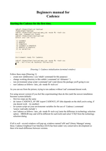
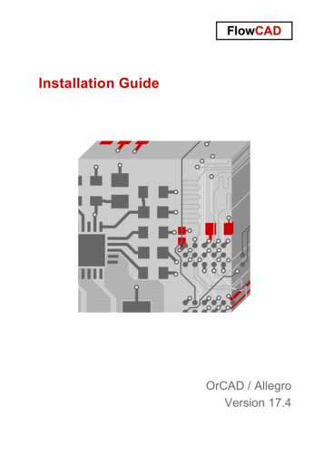
Cadence Design Environment1. INTRODUCTIONThis manual is intended to introduce microelectronic designers to the Cadence DesignEnvironment, and to describe all the steps necessary for running the Cadence tools at the KlipschSchool of Electrical and Computer Engineering.Cadence is an Electronic Design Automation (EDA) environment that allows integrating in a singleframework different applications and tools (both proprietary and from other vendors), allowing tosupport all the stages of IC design and verification from a single environment. These tools arecompletely general, supporting different fabrication technologies. When a particular technology isselected, a set of configuration and technology-related files are employed for customizing theCadence environment. This set of files is commonly referred as a design kit.It is not the objective of this manual to provide an in-depth coverage of all the applications and toolsavailable in Cadence. Instead, a detailed introduction to those required for an analog designer, fromthe conception of the circuit to its physical implementation, is provided. References to othermanuals and information sources with a deeper treatment of these and other Cadence tools are alsoprovided.2. ANALOG IC DESIGN FLOW AND REQUIRED TOOLSFig. 1 shows the basic design flow of an analog IC design, together with the Cadence tools requiredin each step.First, a schematic view of the circuit is created using the Cadence Composer Schematic Editor.Alternatively, a text netlist input can be employed.Then, the circuit is simulated using the Cadence Affirma analog simulation environment. Differentsimulators can be employed, some sold with the Cadence software (e.g., Spectre) some from othervendors (e.g., HSPICE) if they are installed and licensed.Once circuit specifications are fulfilled in simulation, the circuit layout is created using the VirtuosoLayout Editor.The resulting layout must verify some geometric rules dependent on the technology (design rules).For enforcing it, a Design Rule Check (DRC) is performed. Optionally, some electrical errors (e.g.shorts) can also be detected using an Electrical Rule Check (ERC). Then, the layout should becompared to the circuit schematic to ensure that the intended functionality is implemented. This canbe done with a Layout Versus Schematic (LVS) check. All these verification tools are included inthe Diva software in Cadence (more powerful Cadence tools can also be available, like Dracula, orAssura in deep submicron technologies).Finally, a netlist including all layout parasitics should be extracted, and a final simulation of thisnetlist should be made. This is called a Post-Layout simulation, and is performed with the sameCadence simulation tools.Once verified the layout functionality, the final layout is converted to a certain standard file formatdepending on the foundry (GDSII, CIF, etc.) using the Cadence conversion tools.4
Cadence Design EnvironmentSpecificationsCADENCE TOOLComposerSchematic EntryAffirma (Spectre, Hspice, cdsSpice)SimulationNoOK?YesLayout DesignVirtuosoLayoutVerificationNoDiva (or Dracula)OK?YesPost-LayoutSimulationNoAffirma (Spectre, Hspice, cdsSpice)OK?YesFormat conversion (GDSII,CIF, CALMA, etc.)FabricationMeasurementsFigure 1. Analog IC design flow and Cadence tools involved5
Cadence Design Environment3. SETTING YOUR UNIX ENVIRONMENTCadence can be run only on Unix terminals or PCs loaded with Linux (or Unix terminal emulators)and X Windows servers like Exceed, X-Win32, or Xfree (Linux). Also the VNC software can beemployed (see the accompanying document about VNC tools). You need to have a tesla account. Ifyou are using Unix emulators, you can remote logon to the host tesla.nmsu.edu using the SSHprotocols. It your emulator does not support SSH connections, you can first start a telnet session togauss, and then connect to tesla with SSH. Before you can start Cadence, there are a fewconfiguration files that are needed in your home directory. These files determine the environment inwhich Cadence runs, what libraries are to be included in your current session, etc. No doubt thesefiles can be edited to suit personal preferences. The setup given below is tailored for tesla (themachine hosting the Cadence environment at the Department), and for the NCSU Design Kit. Thiskit can be freely obtained from the North Carolina State University, and provides all the necessarytechnology files and simulation models for using several technologies available through MOSIS.Once in tesla, if this is the first time that you are going to use Cadence, copy the required setup files(.cdsinit, .cdsenv, .cdsplotinit, .simrc) and scripts (runNCSU) from the directory/Kits/NCSU/newuser. You can use the following commands, from your home directory (rememberthat the Unix commands are case sensitive):Bash-2.05a cp /Kits/NCSU/newuser/.cds* .Bash-2.05a cp /Kits/NCSU/newuser/.simrc .Bash-2.05a cp /Kits/NCSU/newuser/runNCSU .It is also recommended that this first time you create a new directory for working with Cadence, sothat all the files generated by Cadence will be in that directory. This will be your Cadence workingdirectory in all subsequent sessions, and you will start Cadence from there. E.g., you can type:Bash-2.05a mkdir cadenceThe next step is to enter the directory where you work with Cadence, for instance:Bash-2.05a cd cadenceBefore running Cadence, you have to instruct tesla so that the Cadence windows can be displayedin your PC. You can type:Bash-2.05a DISPLAY yourIPaddress:0Bash-2.05a export DISPLAYwhere yourIPaddress means the IP address of your PC (if you don’t know it, you can get it, e.g.,from http://www.accessam.com/myip.shtml). You can also use the DNS address.4. RUNNING CADENCEOnce your Cadence environment setup you can start working with Cadence. You can run Cadencefrom your working directory by typing:Bash-2.05a /runNCSUor, equivalently, if the parent directory is your home directory,Bash-2.05a ./runNCSU6
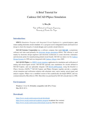
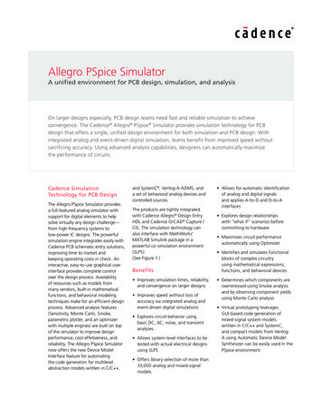
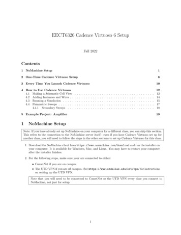
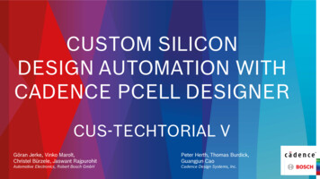
Cadence Design EnvironmentThe Cadence main window (Common Interface Window, CIW) and the Library ManagerWindow are opened. From the CIW menus, all Cadence main tools, online help and options can beaccessed. In the window area, all kind of messages (info, errors, warnings, etc) generated by thedifferent Cadence tools appear. You can also introduce commands. Fig. 2 shows this window.Figure 2. CIW windowAll the entities in Cadence are managed using libraries, and each library contains cells. Each cellcontains different design views (the structure is similar –and physically corresponds - to a directory(library) containing subdirectories (cells), each one containing files (views). Thus, for instance, acertain circuit (e.g. an ADC) can be stored in a library, and such library can contain the differentADC blocks (comparators, registers, resistor strings, etc) stored as cells. Each block (cell) containsdifferent views (schematic, layout, etc.).There are usually three types of libraries: A set of common Cadence libraries that come with the Cadence software (containing basiccomponents, such as voltage and current sources, R, L, C, etc). Libraries that come with a certain design kit and that are related to a certain technology(e.g. transistors with a certain model attached, etc). In the NCSU design kit, some generalCadence libraries are customized and converted into design kit libraries. User libraries; where the user stores its designs. These designs employ components fromthe Cadence/design kit libraries.All the libraries are managed from the Library Manager Window (shown in Fig. 3). It appears bydefault at Cadence start, and can be opened at any time by selecting Tools Library Manager.from the CIW. Libraries with names starting by NCSU are design kit libraries, and contain basiccomponents for building designs. In Fig. 3, they are: NCSU Analog Parts: contains all the required blocks for designing an analog schematic(sources, GND and VDD terminals, transistors, R, L, C, diodes, etc.) NCSU Digital Parts: similarly, it contains all parts required for digital design (logic gates,muxes, etc.) NCSU Sheets 8ths: it contains informative sheet borders for the schematics, in different sheetsizes. Its use is optional, for design documentation. NCSU TechLibAMI06: it is a technology-specific library that is created when the user attachesthis particular technology (AMI06) to a user library.7
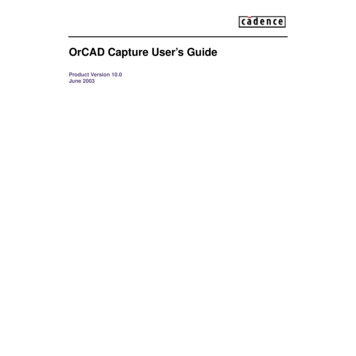
Cadence Design EnvironmentFigure 3. Library Manager window5. ANALOG DESIGN WITH CADENCE DESIGN FRAMEWORK IINow we are going to illustrate how to carry out the complete design flow shown in Fig. 1 using theCadence tools. A simple Operational Transconductance Amplifier (OTA) will be designed in theAMI 0.5µm CMOS technology. However, the same procedures apply to complete chip designs.5.1. Library creation and selection of technologyIt is recommended that you use a library to store related cell views; e.g., use a library to hold all thecell views for a single project (that can involve a complete chip design). In our example, we aregoing to create a new library for our design. From the CIW or from the Library Manager window,a) Select File - New - Library. A new window appears (see Fig. 4).b) Enter a library name, e.g., example.c) Enter the absolute path name if you want the library created somewhere else than the workingdirectory.d) Choose the Attach to an existing techfile option.e) Choose your technology; for instance, for AMI 0.5µm in MOSIS, choose AMI 0.6u C5NNOTE: The NCSU Kit 1.6u and 0.6u AMI processes correspond to MOSIS' 1.5µ and 0.5µ. Forconsistency, the NCSU kit names its tech libs based on the drawn length of devices, so thissometimes runs afoul of MOSIS' naming scheme.8
Cadence Design EnvironmentThis will be the technology chosen for your design (that you will employ eventually forfabrication). Now all the designs made in this library are technology-dependent (e.g., the schematicMOS symbols have by default the model for this technology, the available layout layers correspondto this technology, etc.).Figure 4. Create Library window5.2. Schematic Entry with Composer5.2.1. Transistor-level schematicThe traditional method for capturing (i.e. describing) your transistor-level or gate-level design is viathe Composer schematic editor. Schematic editors provide simple, intuitive means to draw, to placeand to connect individual components that make up your design. The resulting schematic drawingmust accurately describe the main electrical properties of all components and their interconnections.Also included in the schematic are the power supply and ground connections, as well as all "pins"for the input and output signals of your circuit. This information is crucial for generating thecorresponding netlist, which is used in later stages of the design. The generation of a completecircuit schematic is therefore the first important step of the former design flow. Usually, someproperties of the components (e.g. transistor dimensions) and/or the interconnections between thedevices are subsequently modified as a result of iterative optimization steps. These latermodifications and improvements on the circuit structure must also be accurately reflected in themost current version of the corresponding schematic.Now you are going to create the OTA schematic. From the CIW or from the Library Managerwindow,a) Select the library name that you just created, e.g., example.b) Select File - New - Cellviewc) Enter a cell name, for instance, OTAd) Choose Composer - Schematic as the Tool. View name should be schematic.e) Click OK.An empty blank Composer - schematic window should open. In this window you will create yourschematic. The final schematic is shown in Fig. 5 (the icon actions are also shown). To create it,you can employ the window top menus or left icons (or also shortkeys). This multiple access to9
Cadence Design Environmentactions is common to all the Cadence tools. A detailed information concerning the use of theschematic editor can be obtained by selecting Help from this window. Basically, you can: Create components: by selecting the Instance icon and browsing in the pop-up window throughthe different libraries. Most components (transistors, R, L, C, sources, rail terminals, etc.) are inthe NCSU Analog Parts library. When you create an instance of a certain component (e.g.,transistor, R, C, etc.) a window appears where you can select the properties of this element.Note that for transistors, the model is automatically set according to the technology you haveselected, and that some parameters (drain and source area and perimeter, etc) areautomatically calculated.NOTE: There are three-terminal (nmos, pmos) and four-terminal (nmos4, pmos4) MOS devicesavailable. The three-terminal devices have a hidden fourth (bulk) terminal, which is connected bydefault to "gnd!" for nmos and "vdd!" for pmos. This means that you need to have nets named"vdd!"and "gnd!" somewhere in your schematic. (The easiest way to do this is to drop in the vddand gnd pins from NCSU Analog Parts- Supply Nets.) If you don't have these nets in yourschematic somewhere, you'll get complaints about unknown nets either in the netlister or in LVS.(You can also change the bulk node in the three-terminal device if you want to. Just select thedevice in the schematic, and bring up the "Edit Object Properties" form (Edit- Object Properties.). Change the "Bulk node connection" field to whichever net you want. Wire components: select the Wire (narrow) icon, click to the first terminal and drag until theother terminal, then click again.In complex designs, for avoiding excessive wiring, labels can be employed. When two wireends are labeled with the same name, they are effectively connected. Labels are created, e.g.,with the Label icon. Set instance properties: you can modify at any time the properties of a certain componentinstance (resistance value, transistor dimensions, etc), e.g., by selecting the instance (click on it)and then clicking on the Properties icon. You can also change a group of instances of the samecomponent simultaneously, by first selecting this group, then clicking in Properties andmodifying the parameters, selecting Apply to All selected.Most of the commands in Composer will start a mode (the default mode is selection), and as long asyou do not choose a new mode (by clicking an icon, pressing a shortkey or selecting a menu item)you will remain in that mode. To quit from any mode and return to the default selection mode, the"Esc" key can be used.There are basically two ways of creating schematics:a) Non-Hierarchical schematic. You introduce all the circuit schematic at the same (transistor)level, including the required sources. This is only viable for small designs.b) Hierarchical schematic. If your design is very large, or if you want to reuse your design inother designs (e.g. an OpAmp to be employed in other circuits), you should create basic blocksat a low level, then create symbols for them and then use these symbols as basic components ata higher hierarchical level of the design. It is the same concept employed in SPICE netlists withthe .SUBCKT command.10
Cadence Design EnvironmentWhen a certain circuit design consists of smaller hierarchical components (or modules), it isusually very beneficial to use this approach, first identifying such modules early in the designprocess and then assigning each such module a corresponding symbol (or icon) to represent thatcircuit module. This step largely simplifies the schematic representation of the overall system.The "symbol" view of a circuit module is an icon that stands for the collection of allcomponents within the module.A symbol view of the circuit is also recommended for some of the subsequent simulation steps;thus, the schematic capture of the circuit topology is usually followed by the creation of asymbol to represent the entire circuit. The shape of the icon to be used for the symbol maysuggest the function of the module (e.g. logic gates - AND, OR, NAND, NOR), but the defaultsymbol icon is a simple rectangular box with input and output pins. Note that this icon can nowbe used as the building block of another module, and so on, allowing the circuit designer tocreate a system-level design consisting of multiple hierarchy levels.This is the approach that will be followed in our example. For doing this, we have to create asymbol view of our OTA.5.2.2. Symbol Creationa) First, you have to create pins in your schematic in those non-global nets (inputs, outputs,supplies perhaps) that have to be accessible outside the symbol. For doing this, you can selectthe Create Pin icon in the Composer schematic window, select the pin name, its input or outputconfiguration, etc, and then click at the end of the wire when the pin has to be placed. Six pinicons have been placed in the example of Fig. 5: v , v-, ibias, vdd, vss (input pins) and out(output pin).b) Now, select Design Create Cellview From cellview. A window appears that by defaultcreates a symbol view from the schematic view. Just click OK. A black window pops up withthe symbol. It can be edited if desired (changing shape, pin distribution, etc.). Fig. 6 shows theresulting symbol (after some editing) and the actions associated to the left icons.Now you can use your design in a higher hierarchical schematic. For instance, in Fig. 7 a newschematic is created where the OTA symbol is instantiated and some sources are included, forminga voltage follower ready to be simulated. This will be the design that we will simulate subsequently.For instantiating the OTA symbol, the procedure is identical than for any other component. You canselect the Instance icon, go to your library and select the OTA.11
Cadence Design EnvironmentCheck and SaveSaveZoom In by 2Zoom Out by 2StretchCopyDeleteUndoPropertyInstanceWire (narrow)Wire (wide)LabelPinFigure 5. Composer Schematic Editor windowSaveZoom In by 2Zoom Out by LabelSelection BoxFigure 6. Symbol Editor window12
Cadence Design EnvironmentFigure 7. Composer Schematic Editor window, hierarchical designWe can go up and down in the hierarchy with menu options or with shortkeys X (or x, to descend)and b (to ascend). Parameters for voltage and current sources are set as for any other component, byselecting the instance and editing its properties.5.3. SimulationAfter the transistor-level description of a circuit is completed using the Schematic Editor, theelectrical performance and the functionality of the circuit must be verified using a Simulation tool.The detailed transistor-level simulation of your design will be the first in-depth validation of itsoperation, hence, it is extremely important to complete this step before proceeding with thesubsequent design optimization steps. Based on simulation results, the designer usually modifiessome of the device properties (such as transistor width-to-length ratio) in order to optimize theperformance.The initial simulation phase also serves to detect some of the design errors that may have beencreated during the schematic entry step. It is quite common to discover errors such as a missingconnection or an unintended crossing of two signals in the schematic. Some of these errors (e.g.,floating nodes) can be detected even before simulation, by pressing the Check and Save icon in theschematic window.The second simulation phase will follow the "extraction" of a mask layout (post-layout simulation),to accurately assess the electrical performance of the completed design.13
Cadence Design EnvironmentLike in other simulation environments, it is the netlist text file extracted from the schematic (orlayout) what is actually simulated.In order to start simulations, from the Composer window that contains the schematic you want tosimulate (in our example, test OTA, shown in Fig. 7), choose Tools Analog Environment. Thesimulation window appears (Fig. 8).Choose designCircuit to besimulatedChoose analysisList of analyses to be performedSet variablesChoose outputsDeleteDesignVariablesRun simulationStop simulationPlot outputFigure 8. Simulation windowBy default, the design from which we have launched the window can be simulated using Spectre.5.3.1. Setting simulatorWe can change the design with the corresponding icon or using the menus. We can also change thesimulator by choosing Setup- Simulator/Directory/Host and setting e.g., HSPICE. Obviously, thechosen simulator must be installed and licensed.5.3.2. Setting modelsAlso by default the component models for the library technology (in our example AMI 0.5µ) will beused. If we want to use other models, we can store them in some directory and choose Setup Model Path, typing the full path (including filename) of the model(s) needed for simulation,before the path for the default models (list position means precedence in the search for models).This procedure assumes that your models have the same name as the default models.5.3.3. Setting design variablesWe can use in our schematic design variables for the component parameters, so that their values canbe assigned just before simulation. For instance, we can name some (or all) of the transistor lengthsas ‘L’. Then, in the simulation window we assign the desired value to L. This way, we can makeseveral simulations just changing the parameter(s) without having to edit the schematic. For editingdesign variables, choose Variables Edit (or select the corresponding icon).14
Cadence Design Environment5.3.4. Selecting the analysisSeveral analyses can be performed (DC, AC, transient, etc.). For selecting the required analysis,choose Analysis Choose (or the corresponding icon) and complete the settings in the window thatappears.Example: Transient analysis, choose 'tran', ‘conservative’ and then type in the total time you wishto run (ex. 40n or 40e-9)Currents cannot be plotted by default. If you are interested in viewing currents in your circuit,choose: Output Save all . Select all DC/transient terminal currents (for DC and transientanalyses) or Select all AC terminal currents (for AC analysis).5.3.5. Running the simulationWhen the former steps are performed, simulation can start. Click the Green Traffic Light Icon(bottom right corner of the simulation window) or choose Run Simulation to run the simulation.If you want to interrupt the simulation at any instant, click the Red Traffic Light Icon or chooseRun Interrupt.5.3.6. Plotting the simulation resultsThere are different ways of plotting the results of a simulation. Here we are going to use theCalculator tool. After running the simulation, choose Tools Calculator. A calculator windowappears (see Fig. 9).Figure 9. CalculatorWith this tool we can, among other things: Plot in a waveform window the different currents and voltages Print (to a printer or a file) the selected waveforms Perform different functions on the selected waveform (multiply, divide, dB calculation,DFT, THD calculation, bandwidth, maximum and minimum calculation, etc). Use as a normal calculator for making calculationsYou can select the Help option for details.15
Cadence Design EnvironmentWhen we want to display a certain waveform, we first select the button corresponding to the type ofwaveform. The most common are:Vt: nodal voltage (transient analysis)It: terminal current (transient analysis)Vf: nodal voltage (AC analysis)If: terminal current (AC analysis)Vs: nodal voltage (DC sweep)Is: terminal current (DC sweep)Vdc: nodal voltage (quiescent value)Idc: terminal current (quiescent value)Then, we just click on the corresponding wire (voltages) or terminal (currents) in the schematic.Finally, we select in the calculator:Plot: To plot the waveform without removing already displayed waveformsErplot: To remove displayed waveforms and plot the selected one.The waveform is plotted in the Waveform Window. We can continue selecting circuit nodes andselecting plot or erplot. Finally, press Esc for disabling the current action.The Waveform Window, showing the input and output voltages of our voltage buffer, is shown inFig. 10. Different configurations can be chosen (various graphs or axes, cursors, etc.). Press theHelp button for details.If you want to modify and re-simulate your circuit, just change your schematic, design variables orsimulation command, run again the simulation and select Window Update results in theWaveform Window.Figure 10. Waveform window16
Cadence Design Environment5.4. LayoutThe creation of the mask layout is one of the most important steps in the full-custom (bottom-up)design flow, where the designer describes the detailed geometry and the relative positioning of eachmask layer to be used in actual fabrication, using a Layout Editor. Physical layout design is verytightly linked to overall circuit performance (area, speed and power dissipation) since the physicalstructure determines the transconductances of the transistors, the parasitic capacitances andresistances, and obviously, the silicon area that is used to realize a certain function.The physical (mask layout) design is an iterative process, which starts with the circuit topology andthe initial sizing of the transistors. It is extremely important that the layout design must not violateany of the Layout Design Rules of the fabrication process, in order to ensure a high probability ofdefect-free fabrication of all features described in the mask layout. It is also important to Extractthe netlist underlying the layout view, for two main purposes: This allows comparing it with the netlist extracted from the schematic. This Layout versusSchematic (LVS) comparison ensures that the l
This manual is intended to introduce microelectronic designers to the Cadence Design Environment, and to describe all the steps necessary for running the Cadence tools at the Klipsch School of Electrical and Computer Engineering. Cadence is an Electronic Design Automation (EDA) environment that allows integrating in a single .