Transcription
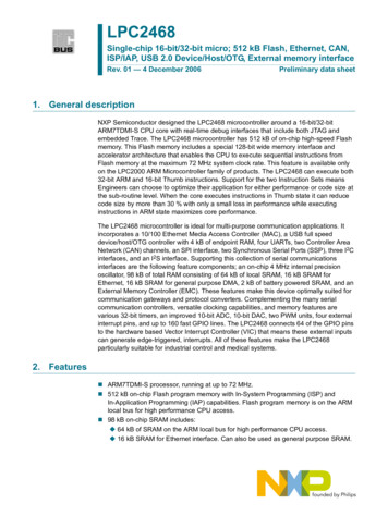
Chapter 16Oscillator Circuits and Applications16.0 IntroductionOscillator contains circuit that generates an output signal without necessity of aninput signal. It is a circuit that produces a repetitive waveform on its output withonly dc supply as input. The oscillator can be sinusoidal or non-sinusoidal type.They can be used in many applications such as communication and digitalsystem.Oscillator operation is based on positive feedback whereby portion β of theoutput signal Vout is feedback without phase φ change. This shall mean thatthere is no phase difference between the input and feedback signal.Many oscillator circuits can be designed using operational amplifier circuit.It can generate various types of waveform with no input other than dc supply.These are known as signal generators or oscillators.16.1 Principles of OscillatorWith exception such as relaxation oscillator, the operation of oscillator is basedon principle of positive feedback where portion of the output signal is feedbackinto input without phase change. Thus, it reinforces the input and sustains thecontinuous sinusoidal output. Beside this, the phase shift of feedback signalmust be either 0o or 360o. The last requirement is the loop gain T of amplifiermust be equal to one, which is also named as Barkhausen criterion. Thusmathematically, the loop gain T isT AVβ 1(16.1)where AV is the voltage gain of the amplifier and β VfVoutis the feedbackportion of output voltage. If AV is equal to 10 then the feedback portion βshould be 1/10. The principles of the oscillator are illustrated in Fig. 16.1. Thetransfer function of the circuit shall be Af - 441 -AV.1 A Vβ
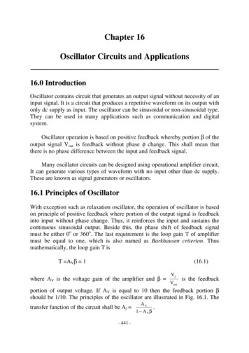
16 Oscillator Circuits and ApplicationsFigure 16.1: Principle of sinusoidal oscillator16.2 Non Sinusoidal OscillatorTriangular wave, square wave, and waveform from voltage controlled oscillatorVCO are examples of non-sinusoidal waveforms. Generally, they can bedesigned using operational amplifier, resistor, and capacitor.16.2.1 Triangular Wave OscillatorA basic triangular wave generator is shown in Fig. 16.2 and its waveform isshown in Fig. 16.3. When the switch is at position 1, which is at negativevoltage, the output of the operational amplifier will ramp from negative topositive voltage. Likewise, when the switch is at position 2, which is at positivevoltage, the output of the op-amp will ramp from positive to negative voltage.Figure 16.2: A basic triangular waveform generator- 442 -
16 Oscillator Circuits and ApplicationsThe waveform of the basic triangular waveform is shown in Fig. 16.3, which istderived from integrator Vout1 2 Vdt VC ( t 0) , where Vc(t 0) is theRC t 1voltage of capacitor at time t 0.Figure 16.3: The basic principle of a triangular wave generatorA practical triangular wave generator is shown in Fig. 16.4 whereby its positiveand negative peak voltage and period can be specified.Figure 16.4: A practical triangular wave generatorThe peak-to-peak output voltage Vout(PP) is,Vout(PP) VUTP -VLTPwhere VUTP (16.2)R3R( Vout (max) ) and VLTP 3 ( Vout (max) ) . Vout(max) and -Vout(max) areR2R2the positive and negative output swing of the comparator. The resonantfrequency fr of this triangular wave is- 443 -
16 Oscillator Circuits and Applicationsfr 1 R2 4R 1C R 3 (16.3)Based on equation (16.3), by varying the value of resistor R1 will change thefrequency of the oscillator but not the peak-to-peak voltage, which is governedby equation (16.2).16.2.2 Saw tooth Wave OscillatorA saw tooth wave generator utilizes the concept of voltage-controlled oscillatorVCO. It can be designed by using a programmable unijunction transistor PUTand an operational amplifier integrator arranged as shown in Fig. 16.5.Figure 16.5: A saw tooth wave generator circuit using PUTA negative input voltage Vin is used to establish a positive ramping voltagewhereby at this stage the capacitor C is charging and the output Vout is rampingup. As soon as the output voltage reaches the programmed voltage VP ofprogrammable unijunction transistor PUT plus the forward voltage VF of thediode, which is 0.7V, the PUT is conducting causing the capacitor to dischargeand output voltage drop abruptly to the forward voltage VF of the programmableunijunction transistor PUT.The period T of the wave isT VP VFVin RC(16.4)- 444 -
16 Oscillator Circuits and Applicationswhere Vin RC is ramping rate of output voltage.Saw tooth wave can also be designed using the triangle wave circuit withinclusion of reference voltage Vref at the non-inverting input pin of theintegrating operational amplifier. The circuit of the design is shown in Fig. 16.6.Figure 16.6: A saw tooth wave generator circuit design using square wave circuitR4 is the potentiometer that is used to provide Vref voltage to the integrator. Bycontrol Vref voltage, shape of the saw tooth wave can be varied.The time t1 of the positive ramping of the wave is t1 R2R 1 C 3 ( Vout (max) ) . The time t2 for the negative ramping of the wave( Vout (max) ) Vref R 2is t2 R2R 1 C 3 ( Vout (max) ) . If we assume that the saturation voltages of( Vout (max) ) Vref R 2the operational amplifier is the same. i.e. ( Vout(max)) (-Vout(max)) Vout(max),then the period T of the saw tooth wave is equal toT Theduty4R 1C(Vout (max) ) 2(Vout (max) ) Vcycle2of2refthe R3R2saw(16.5)tooth(Vout (max) ) VR2R 1CR 3 (Vout (max) ) 22(Vout (max) ) Vref R 24R 1C(Vout (max) ) R 322refwave isequalto Vref 1 1 . Fixing duty2 Vout (max) cycle and knowing Vout(max), Vref can be known and adjusted using R4.- 445 -t1/T
16 Oscillator Circuits and Applications16.2.3 Square Wave OscillatorThe square wave oscillator is designed based on the principle of charging anddischarge of the capacitor and comparator, which is shown in Fig. 16.7.Figure 16.7: Square wave oscillatorWhen the circuit is turned on, the voltage at inverting input is zero. Thus, theoutput of the op-amp is swung to maximum positive value, which should be thepositive saturation voltage of the operational amplifier. The capacitor begins tocharge until the voltage VC is just greater than the feedback voltage Vf, which isR3Vout . At this point, the output of the op-amp is swung to minimumR2 R3negative value, which is the negative saturation voltage of the op-amp. Thiswould cause the capacitor to discharge. When the voltage VC reaches negativeVf, the output of op-amp swings to positive again. This process repeats andgenerates square wave. The period T of the oscillation can be shown to followequation (16.6).T 2R1C1ln(1 2R3/R2)(16.6)It can be calculated using charging equation VC1 Vout (-Vf – Vout)exp(t/R1C1) for VC1 Vf and discharging equation VC1 - Vout (Vf Vout)exp(t/R1C1) for VC1 - Vf.If the value of resistor R2 is R2 1.1639R3, then the period T is T 2R1C1.- 446 -
16 Oscillator Circuits and Applications16.3 Oscillators with RC Feedback CircuitMany oscillators are designed utilizing RC network and resistor divider circuits.RC network is basically used to determine the resonant frequency of theoscillator, whilst resistor divider circuit is used to provide attenuated feedback.Generally oscillator with RC network can provide frequency not more than1MHz. For oscillator that can provide frequency more than 1MHz, LC networkis used.16.3.1 Wien-Bridge OscillatorWien-Bridge oscillator is an oscillator that meets the principle of oscillator. Itscircuit is shown in Fig. 16.8.Figure 16.8: Wien-Bridge oscillatorThere is a lead-lag RC network whereby C1 and R3 leads and R4 and C2 lags.Reactance χ C of capacitance C1 is significantly affecting the VIN at lowfrequency, whilst reactance χ C of capacitor C2 equal to 1/jωC 2 is significantaffecting at high frequency. If C1 C2 and R4 R3, there will be no phase-shiftbecause the phase lead is compensated by phase lag.12From the analysis of the circuit, the portion of the output feedback to inputβ VfVoutshall be- 447 -
16 Oscillator Circuits and Applicationsβ VfVout jωRC3 jωRC (1 ω 2 R 2 C 2 )(16.7)Applying Barkhausen principle of oscillator design this shall mean that overallloop gain A jωRCAV 1. From real part and imaginary part of3 jωRC (1 ω 2 R 2 C 2 )the complex number solution, the resonant frequency fr of the oscillator shall befr 12πRC(16.8)The voltage gain AV of the amplifier should be 3. This shall mean that feedbackportion β is 1/3.Since the voltage gain of the amplifier AV should be 3, this shall mean thatAV R1 R 2 3R2(16.9)In order for Wien-Bridge oscillator to start oscillating, the initial voltage gainAV should be slightly more than three. Adding an extra circuit, which is calledstability circuit as shown in Fig. 16.9, will provide self-start and sustain theoscillation.Figure 16.9: Self-starting and sustaining Wien-Bridge oscillator- 448 -
16 Oscillator Circuits and ApplicationsBefore zener diode D1 and D2 conduct, the voltage gain AV of the amplifier isAV R1 R 2 R 5R 3 5 R2R2R2(16.10)Thus, it meets the conditions of closed loop gain greater than 1 for self-startingof the oscillator.When the output voltage reaches the zener breakdown voltage plus 0.7V,the zener diode conducts. Its forward resistance would be much smaller than theresistance value of resistor R5. Thus, the closed loop gain will be back to 1 andoscillation would be sustained.16.3.2 Operational Amplifier Phase-Shift OscillatorThe operational amplifier phase-shift oscillator is another oscillator type thatmeets the principles of oscillator design. Its circuit is shown in Fig. 16.10.Figure 16.10: Operational amplifier phase-shift oscillatorThe feedback portion of the oscillator can be derived by applying Kirchhoff’scurrent law at node a and node b respectively. Current i1 is i1 - 449 -Vb sCV, i2 b ,1 sRCR
16 Oscillator Circuits and Applicationsi3 (Va – Vb)sC, i4 to Vb 1 sRC Vf .sRCVa, and i5 (Vout – Va)sC. Voltage at node b is also equalRAt node b, current i3 i1 i2; (Va Vb )sC Vb sCV b . This implies that1 sRC RVa Vb 11 1 . 1 sRC sRc At node a, i5 i1 i2 i4; (Vout Va )sC Vout sC Vb sCVV b a . This implies that1 sRC RRVb sCVV b a Va sC . Substituting the expression of Va and Vb into1 sRC RRthe above equation yields equation (16.10), which is the feedback portion β.β VfVoutj 3 ω3 R 3 C 3j 3 ω3 R 3 C 3 6 j 2 ω 2 R 2 C 2 5 jωRC 1 (16.11)After applying Barkhausen principle of oscillator design, from real part of thecomplex number denominator, which is (1-6ω2R2C2) 0, the resonantfrequency fr of the oscillator shall befr 12 π 6RC(16.12)j 3 ω3 R 3 C 3 A VFrom the imaginary part of the complex number, which is 3 3 3 3 1,j ω R C 5 jωRCthe voltage gain AV of the amplifier shall beAV 1 5ω R 2C2(16.13)2From equation (16.12), this shall mean that ω 2 1. Substituting this6R 2 C 2expression into equation (16.13), it yields AV -29. This shall mean that theattenuation of the three-section RC feedback is 29. Therefore, the value of Rf/Ri should be 29.- 450 -
16 Oscillator Circuits and Applications16.3.3 Quadrature OscillatorQuadrature oscillator as shown Fig. 16.11 generates two signals both sine andcosine that are in quadrature meaning out of phase by 900. The sine and cosineoutputs can be arbitrary assigned. It is not necessary to assign output ofoperational amplifier 1 as sine output and output of operational amplifier 2 ascosine output.The feedback portion β is Vin1/VO2 1. The gain of operational1 sRC1 sRC. Similarly, the gain of operational amplifier 2 issRC11 sRCAVO2 . The overall gain AV is . Applying Barkhausen principlesRC(sRC)211 sRCof oscillator design, the loop-gain of the oscillator is AVβ 1 sRC (sRC )21 and is equal to one. This shall imply that s2R2C2 -1. Based on this2(sRC)amplifier 1 is AVO1 equation, frequency f of the oscillator isf 12πRC(16.14)Figure 16.11: Quadrature oscillator- 451 -
16 Oscillator Circuits and ApplicationsSubstituting equation (16.14) into the equation of feedback portion β, which isVin1/Vo2 111, the feedback portion β is 450 . This shall mean1 sRC1 j21that its magnitude is2. This implies that overall open loop gain of the1 sRC, after substitutingsRCω with equation (16.14), the gain function becomes AVO1 j (1 j ) 12 45 0 . Similarly the gain function AVo2 is AVo2 1 90 0 . The totalsRCoscillator AV is 2 1.41 . The gain function is AVo1 phase shift is -450 - 450 900 0 that meets the design principle.16.3.4 Three-Phase OscillatorThree-phase oscillator as shown Fig. 16.12 generates three sinusoidal voltagesof equal magnitude but displaced by 1200 from each other.Figure 16.12: Three-phase oscillatorThe feedback portion β is equal to one. The gain of each operational amplifier isAVi R F (1 / sC)R /R F. The overall gain AV of the oscillator is AV R1 sR F C3 RF / R . Applying Barkhausen principle of oscillator design, the loop-gain 1 sR F C - 452 -
16 Oscillator Circuits and Applications3of the oscillator shall be R /R AVβ F 1 sR F C 1. This implies that3 R (sR F C) 3(sR F C) 3(sR F C) 1 F 0 . Equating the imaginary part of the R 32equation, it gives rise to the frequency of the oscillator to bef 32πR F C(16.15)Equating the real part of the equation, it gives rise to the gain of individualRF 2 . Substituting the gain equation and frequency equationRR /R2into AVi F, it produces gain function 1 120 0 .1 sR F C1 j 3integrator to be16.4 Oscillators with LC Feedback CircuitLC element is used for oscillators that generate more than 1.0 MH frequency.Also because of frequency limitation of most operational amplifier, discretetransistor is used as gain element of LC oscillator.16.4.1 Colpitts OscillatorColpitts oscillator utilizing operational amplifier is shown in Fig. 16.13 and adiscrete bipolar junction transistor version is shown in Fig. 16.14. The oscillatoruses LC network in the feedback loop. The combination of C1 and C2 and L actas a parallel resonant circuit. Using Kirchhoff's current law and ac model asshown in Fig. 16.15 for circuit, the current at output node is gmVbe I1 I2 I3VoutVoutVout 0 and using voltage divider law,R 3 1 / jωC1 jωL 1 / jωC 21 / jωC 2base-to-emitter voltage Vbe equals to Vbe Vout . From these twojω L 1 / jω C 2 0 i.e. g m Vbe 2 jω[(C1 C 2 ) ω 2 LC1C 2 ] 0 . equations, it yields expression g m RR33 Thus, the resonant frequency fr is obtained from the imaginary part of theequation, which is jω[(C1 C 2 ) ω 2 LC1C 2 ] 0 and it is expressed as 1- 453 -ω 2 LC
16 Oscillator Circuits and Applicationsfr 1(16.16)CC2π L 1 2C1 C 2Figure 16.13: Colpitts oscillator[] 1 ω 2 LC 2 jω (C1 C 2 ) ω 2 LC1C 2 0 , itFrom the real part of equation g m R3R3 ω 2 LC 21yields gm . Combining this equation with equation (16.16), itR3R3yields gain AV gmR3 C2/C1. Thus, the feedback portion shall be β C1/C2.Figure 16.14: A discrete Colpitts oscillator- 454 -
16 Oscillator Circuits and ApplicationsFigure 16.15: ac model of a discrete Colpitts oscillatorThe impedance of the transistor will act as the load on the resonant circuit andreduced the quality factor Q ω0of the circuit thus reduced the resonantωH ωLfrequency of the circuit. The equation of resonant frequency for Colpittsoscillator including Q factor isfr 1CC2π L 1 2C1 C 2 Q2Q2 1(16.17)If the Q factor is less than 10, the resonant frequency is significant reduced. Onthe other hand, if the Q factor is greater than 10, the factorQ2isQ2 1approximately equal to one, which shall mean it does not affect the resonantfrequency of the circuit.16.4.2 Hartley OscillatorThe Hartley oscillator is shown in Fig. 16.16. Using the similar approach likethe way how gain and resonant frequency are derived for Colpitts oscillator, theresonant frequency of Hartley oscillator can be shown equal tofr 1(16.18)2π (L1 L 2 )Cwhere inductor L1, L2, and capacitor C act as resonant circuit.- 455 -
16 Oscillator Circuits and ApplicationsThe feedback portion β of this oscillator is L1/L2. Therefore, the gain ofthis amplifier should be slightly greater than L2/L1 for self-starting. This shallmean that the ratio L2/L1 is also equal to ratio Rf/Ri, which is the gain AV of theamplifier.Figure 16.16: Hartley oscillator16.4.3 Clapp OscillatorThe Clapp oscillator is a variant of the Colpitts oscillator. As shown in Fig.16.16, the equivalent capacitance Ceq is equalC eq 1111 C1 C 2 C 3(16.19)If the Q factor is greater than 10, then the resonant frequency of the oscillator isequal tofr 12π LC eq(16.20)If capacitor C3 is very much smaller than C1 and C2, then the equivalentcapacitor Ceq is Ceq C3.- 456 -
16 Oscillator Circuits and ApplicationsFigure 16.17: Clapping oscillator16.4.4 Armstrong OscillatorArmstrong oscillator uses the transformer and the feedback is via the secondarycoil of the transformer. This oscillator is also called "tickler" oscillator becauseof the secondary coil is as feedback. The circuit of the oscillator is shown in Fig.16.18. The resonant frequency fr of the circuit isfr 12 π L 1 C1(16.21)Figure 16.18: Armstrong oscillator- 457 -
16 Oscillator Circuits and Applications16.5 Crystal Controlled OscillatorThe most accurate and state of arts oscillator is the one that uses piezoelectriccrystal in the feedback loop to control the frequency. Quartz is one type ofcrystalline substance that found in nature that exhibits piezoelectric effect.When a changing mechanical stress is applied to the crystal, it vibrates and avoltage is developed at the frequency of mechanical vibration. If ac voltage isapplied, it vibrates at the frequency of applied voltage. The crystal has its natureresonant frequency which is determined by its physical dimension and the waythe crystal is cut. A quartz crystal can be represented by the symbol and circuitshown in Fig. 16.19.(a) Symbol(b) Electrical Equivalent circuitFigure 16.19: Symbol and equivalent circuit of quartz crystalPiezoelectric crystal can oscillate in two modes, which are the fundamental orovertone modes. The fundamental mode is the lowest frequency, which is itsnatural frequency. The fundamental frequency is basically depended on thecrystal's dimension, type of cut, and is inversely proportional to the thickness ofcrystal slab. Most crystal can operate up to 20MHz, thus it is necessary toovertone in the odd multiple of the fundamental mode frequency. Assuming thatRs is small, the impedance Z(jω) of the crystal shall beZ( jω) ω 2 (1 / L s C s )1 .jωC m ω 2 [C m C s ) /(L s C s C m )]A basic crystal oscillator is shown in Fig. 16.20. Capacitor CC is used tofine tune the frequency of the oscillator.- 458 -
16 Oscillator Circuits and ApplicationsFigure 16.20: Crystal oscillator16.6 The NE/SE 555 TimerThe NE/SE 555 timer has two comparators, a RS flip-flop, a discharge transistorQd, and relative voltage divider formed by resistor RA, RB, and RC as shown inFig. 16.21. The relative voltage divider can also be externally control using thevoltage control pin (5).NE/SE 555 timer can be configured to form many applications such asmonostable multivibrator, voltage control oscillator, square wave generator,astable multivibrator, and etc.Figure 16.21: The internal structure of NE/SE 555 timer- 459 -
16 Oscillator Circuits and Applications16.6.1 Astable MultivibratorThe relative voltage divider of NE/SE 555 timer has three resistors of equalvalue. This would create a 2/3VCC reference for the upper comparator and1/3VCC reference for the lower comparator. The output of the comparator is thenused to control the output-state of the RS flip-flop. The threshold input isnormally connected to an external RC timing circuit, which is shown in Fig.16.22. When the voltage of external capacitor exceeds 2/3VCC, the uppercomparator reset the flip-flop. This will cause the Q state of the RS flip-flop toswitch high. This in term causes the transistor Qd to switch on and allows thecapacitor to discharge through it via resistor R2. When the voltage of thetransistor reached 1/3VCC, this causes the lower comparator to set the RS flipflop. The Q state of flip-flop is set to zero state, switches-off the transistor Qdand the capacitor will begin to charge up. This process creates a square pulse atthe output of the timer.The frequency of the oscillation is depending on the value of resistor R1and R2 and external capacitor Cext according to the equation (16.22).fr 1.44(R 1 2R 2 )C ext(16.22)Figure 16.22: NE/SE 555 timer connected as an astable multivibrator- 460 -
16 Oscillator Circuits and ApplicationsThe duty cycle of the pulse at output is not symmetrical because the externalcapacitor Cext is charged through resistor R1 and R2 and discharged throughresistor R2 only. Moreover, the charging occurs from voltage 1/3VCC to 2/3VCCand the discharging occurs from voltage 2/3 VCC to 1/3VCC. The charging ofexternal capacitor constitutes the time duration tH for the output is high and itfollows equation (16.23).tH 0.693(R1 R2)Cext(16.23)The time tL is the time duration when the output is low. It follows equation(16.24).tL 0.693R2Cext(16.24)The period T of the output waveform is equal to the sum of tH and tL, which isT 0.693(R1 2R2)Cext(16.25)The reciprocal of period T is the frequency of the output waveform, which isalso equation (16.22). The charging time tH can be obtained from charging VCC VCC e t /( R1 R 2 ) Cext by setting VCext 2VCC/3, which 3 equation VCext VCC yields tH (R1 R2)Cext ln 2, whilst the discharge time can be obtained fromequation VCext 2VCC t / R 2C exteby setting VCext VCC/3, which yields tL R2Cext3ln 2. The duty cycle of the waveform follows equation (16.26).Duty cycle tHx100% tL tH R1 R 2 x100% R 1 2R 2 (16.26)To obtain closed to 50% duty cycle, the value of resistor R2 has to be muchgreater than the value of resistor R1. This will make the charging anddischarging times of the external capacitor Cext almost the same since R1 R2 isapproximately equal to R2. If the pulse is properly negatively offset, then asquare wave is obtained.If the duty cycle of less than 50% is desired, besides selecting value of R1 R2, a diode D1 is connected in parallel with resistor R2 as shown in Fig. 16.23.This will reduce the effective charging time via resistor R1 and forward resistorof diode RF, which is small as compared to value of resistor R2, to be muchsmaller than discharge time via resistor R2. Since, the charge time is much- 461 -
16 Oscillator Circuits and Applicationsshorter than discharge time, the duty cycle is less than 50%. Duty cycle is nowgoverned by equation (16.27).R 1 R diode x100% RRRdiode2 1 Duty cycle (16.27)Rdiode is the forward resistance of the diode, which can be assumed to be zero ascompared with the value of R1 and R2.Figure 16.23: NE/SE 555 timer configured for less than 50% duty cycle16.6.2 Monostable MultivibratorNE/SE 555 timer can be configured as a monostable multivibrator as shown inFig. 16.24. In the stable state, the RS flip-flop is in reset state. The output of thetimer will be at low state. The voltage VC at capacitor C is zero volt because thetransistor Qd is switched on. As soon the triggering voltage Vtrigger is set, whichshall mean the voltage is lower than 1/3VCC. The lower comparator will set theRS flip-flop, which in turn switch-off transistor Qd and set the output to highstate. Since the transistor Qd is off, the capacitor C begins to charge up. As soonas its voltage reaches 2/3VCC, the output of upper comparator switches to highstate and reset the RS flip-flop. The output of timer shall then switch to lowstate and the capacitor begins to discharge through the switched-on transistorQd. The waveforms of the triggering, voltage at capacitor C, and output voltageare shown in Fig. 16.24.- 462 -
16 Oscillator Circuits and ApplicationsFigure 16.24: NE/SE 555 timer configured as a monostable multivibratorThe pulse width twidth of the monostable multivibrator is calculated from thecharging time of RC network charging for voltage from zero volt to 2/3VCC. Thepulse width follows equation (16.28).twidth 1.098RC(16.28)Pulse width twidth can be obtained from universal charging/discharging equationVC Vf (Vi –Vf)exp(-t/τ), where Vi 0 and Vf VCC that yields equation VC VCC – VCCexp(-twidth/RC). By setting VC 2VCC/3, the final charge voltage ofcapacitor, it yields twidth RC ln 3.If the triggering voltage Vtrigger is a pulse of known frequency and the timetwidth is controlled such that it is equal to 1.2 times of the period T of Vtrigger pulsethen the monostable multivibrator is become a divide-by-two frequency divider.In general, for the monostable multivibrator to be configured as divide-byn frequency divider, the pulse-width twidth should be equal to [0.2 (n-1)]T.16.6.3 Voltage Controlled OscillatorThe NE/SE 555 timer can also be configured as a voltage controlled oscillatorVCO. This can be achieved by connecting an external voltage Vcont to voltage- 463 -
16 Oscillator Circuits and Applicationscontrol pin (5). The external voltage changes the threshold value of the lowerand upper comparator from 1/3VCC to 1/2Vcont and 2/3VCC to Vcont. An increaseof Vcont value increases the charging and discharging time and causes thefrequency of the output waveform to decrease and vice versa. The period T ofvoltage controlled oscillator VCO can be obtained from the universalcharging/discharging equation VCext Vf (Vi –Vf)exp(-t/τ).Vcontand Vf VCC, thus, the charging2 V cont VCC e t /( R1 R 2 ) Cext . Setting VCext Vcont, the 2 During the charging phase, Vi equation shall be VCext VCCcharging time tH shall be VCC Vcont / 2 VCC Vcont tH (R1 R2)Cext ln (16.29)During the discharging phase, Vi VCont and Vf 0, thus, the charging equationshall be VCext Vcont e t / R C . Setting VCext Vcont/2, the discharging time tL shallbe2exttL R2Cext ln 2(16.30)The period T of the VCO is VCC Vcont / 2 R2Cext ln 2V Vcont CC T (R1 R2)Cext ln (16.31)The voltage controlled ascillator can be implemented using a integrated circuitNE/SE 566 chip. This intergated circuit VCO produces two simultaneouslysquare wave and triangular wave at the frequency upto 1.0 MHz. The basicblock diagram of the VCO is shown in Fig. 16.25.VCO can also be considered as voltage-to-frequency converter since theinput voltage determines the frequency of the output. NE/SE 566 VCO has acurrent source that consists of the lower current source and upper currentsource. The schmitt trigger has two threshold voltages namely the lowerthreshold voltage VL and upper threshold voltage VH. The upper current sourceis used to charge the external capacitor from VL voltage to VH voltage. Thelower current source is used to discharge the external capacitor from VH voltageto VL voltage. Beside providing square wave, the output of the schmitt trigger is- 464 -
16 Oscillator Circuits and Applicationsalso used to control the switching of lower and upper current source. Thetriangular wave is provided by the charging and discharging of the externalcapacitor via pin (7). The modulated input VCN is consist of a dc voltage and anac modulated signal Vcn coupled with capacitor.Figure 16.25: Block diagram of NE/SE 566 voltage controlled oscillatorFigure 16.26 shows the circuit connection of a NE/SE 566 VCO. The dc VCNvoltage is equal toR3 VCC , in which it must satisfy condition thatR2 R33VCC VCN VCC .4Figure 16.26: Circuit connection of NE/SE 566 voltage controlled oscillator- 465 -
16 Oscillator Circuits and ApplicationsThe modulated input signal Vcn must be 3VPP, where VPP is the peak-to-peakvoltage of the output wave.The time taken to charge the capacitor C1 from voltage VL to VH is t1 C1(VH VL ) and time taken to discharge capacitor C1 from VH to VL is t2 IQC1(VH VL ) , where IQ is the current source with assumption that both the lowerIQand upper current source are sourcing same current. The period T of theoscillator is equal to the sum of the charging and discharging, which isT 2C 1 (VH VL )IQ(16.32)Source current IQ can be proved to be equal to I Q VCC VCN. Thus, subtitutingR1this equation into equation (16.32) yields the period of the oscillator as equal toT 2C1 R 1 (V V )(VCC VCN ) H L(16.33)Usually the value of R1 is in the range between 2 kΩ and 20 kΩ and a capacitorC2 of 0.001 µF is connected to prevent internal oscillation. The value of (VH –VL) can be assumed to be VCC/4.One can replace VCN with an ac Vcn superimposed on dc VCN to getfrequency-modulated output with dc VCN as the control for center frequency anddc VCN Vcn as the control for lower and upper band-frequencies.16.7 Function GeneratorA function generator is capable of producing sine wave, square wave, triangularwave. One of popular such device is XR-2206 from EXAR. Beside generatingsine wave and square wave, this device can be configured to produce pulse,ramp function, and frequency shift keying function FSK. Student is encourgedro obtain the data sheet of this device to study its capability of functiongeneration.- 466 -
16 Oscillator Circuits and Applications16.8 Phase-Lock LoopLet’s consider a phase-lock loop, which is often using in the communicationcircuit as the input frequency locker. There are many other applications of thephase-lock loop PLL such as used in FM stereo decoders, tracking filter FSKdecoder, and frequency-synthesized transmitters and receivers.Phase-lock loop consists of a phase detector, a low-pass filter, and voltagecontrolled oscillator VCO used to feedback to the phase detector. The blockdiagram of the phase-lock loop is shown in Fig. 16.27.Figure 16.27: Block diagram of a phase-lock loop PLLWhen the input frequency is not same as the frequency of voltage controlledoscillator VCO, there is a pha
There is a lead-lag RC network whereby C 1 and R 3 leads and R 4 and C 2 lags. Reactance χC 1 of capacitance C 1 is significantly affecting the V IN at low frequency, whilst reactance χC 2 of capacitor C 2 equal to 1/j ωC2 is significant affecting at high frequency. If C 1 C 2 and R 4 R 3, there will be no phase-shift