Transcription
DATASHEETCadence PCB signal and powerintegrity technology is available inthe following product offerings: Cadence Allegro PCB SI L, XL,and GXL Cadence OrCAD Signal ExplorerCadence PCB Signal andPower IntegrityCadence provides integrated high-speed design and analysisenvironment for streamlining the creation of high-speed interconnect on digital printed circuit board (PCB) systems.A range of advanced capabilities make it easy for electricalengineers to explore, optimize, and resolve electrical performance-related issues at all stages of the design cycle.By enabling a constraint-driven design flow this unique environment increases the likelihood of first-time successand reduces the overall costs of end-products.Cadence PCB Signaland Power IntegritytechnologyCadence PCB signal integrity (SI) andpower integrity (PI) technologies provide ascalable, cost-effective pre- and postlayout system interconnect design andanalysis environment. They deliveradvanced analysis at the board, multiboard, and system levels. Cadence PCB SIand PI products integrate tightly withCadence PCB editors, Cadence Allegro PCB Router, Allegro Design Entry HDL,and Allegro System Architect, enablingend-to-end, constraint-driven, high-speedPCB system design.Cadence PCB SI addresses the challengescreated as a result of increasing designdensity, complexity, and faster edge ratesby enabling designers to address highspeed issues throughout the design process. This approach allows design teamsto eliminate time-consuming simulate-fixsimulate iterations at the back-end of adesign process. It also enables designersto maximize electrical performance whileminimizing cost of the overall product byexploring topologies and models withmanufacturing tolerances. Cadence PCBSI allows users to weigh the trade-offsinvolved in routing choices (rules) thataffect cost relative to electrical performance and reliability. Once developed,these optimum constraints then drivethe physical layout and routing of thePCB. The integrated design and analysisenvironment eliminates the need to translate design databases to run simulations. Designers can also address shrinkingtiming margins by considering the effectsof package design on the overall performance of the signal from die-to-die.Importantly, the integrated flow allowsdesigners to easily perform pre-and postlayout extraction and verification of complex high-speed PCB systems.Cadence PCB SI and PI technology is available in the following product offerings: Cadence Allegro PCB SI L, XL, and GXL Cadence OrCAD Signal Explorer
BENEFITS Reduces the time required to designhigh-speed interconnects and increasesthe likelihood of first-pass success Shortens the time required to developoptimum constraints and enables aconstraint-driven PCB design flow Improves product performance throughsolution space exploration Reduces unit costs of end products byusing the Allegro PCB PI Option XL todesign the PCB power delivery systemnetwork Eliminates the need for physical prototypes for multiple qualificationsof Multi-Gigabit per second seriallinks through advanced simulationtechniques Shortens design cycle time throughfaster tradeoffs of MGH signals usingS-Parameters and single or coupledanalytical via modeling Improves product quality, cost,and performanceSOURCE SYNCHRONOUS,COMMON CLOCKSIGNAL DESIGNSIGXPLORER MODULECadence PCB SI technology contains amodule for pre-route topology designand analysis even before a schematic iscreated (the SigXplorer module). This typeof analysis is common at the earlieststages of the design cycle when designersassess the impact of using a new devicetechnology or of increasing bus transferrate. SigXplorer can be used to build andvalidate detailed electrical topology models and prove the viability of a newtechnology—before the detailed designprocess begins.SigXplorer is a graphical topology designenvironment that allows design engineersto prototype critical signals, understandsensitivity, and use “what-if” scenariosto develop optimum constraints. By performing this type of analysis at theearliest stages of the design cycle, esigners can assess the impact of usingd a new device technology or of increasingedge rates.Using Cadence PCB SI technology, userscan extract a net from Cadence PCBeditors that provides an electrical view ofa physical topology, including vias andchanges in interconnect that affectimpedance or velocity. This allows thedesign engineer to perform “what-if”investigations of electrical behaviorwithout having to edit the PCB design.The engineer can investigate the effectsof changing parameter values anddevelop an acceptable solution withoutdisrupting the PCB design process. Thisability is available at any stage of the PCBdesign process, from schematics, fromPCB with placement through to a fullyrouted board.SOLUTION SPACE EXPLORATIONAllegro PCB SI provides the best environment for users who need to developoptimal constraints through solution Saves time via a virtual prototypingenvironment that is seamlessly integrated with other Allegro platformdesign products Shortens the time required to design-inadvanced devices through the use ofCadence design-in IP portfoliosfeaturesINTEGRATED HIGH-SPEED DESIGNAND ANALYSISAllegro PCB SI reads and writes to theAllegro PCB Editor database to avoidpossible translation issues and allows forconstraints and models to be embeddedin the board design file. The integrateddesign and analysis system is aware ofmulti-net electrical constructs from frontto back. For example, differential pairsand extended nets (nets with a seriestermination) are recognized, extracted,and simulated as one electrical net.(See Figure 1.)www.cadence.comFigure 1: Allegro PCB SI allows engineers to explore and develop optimum constraints with a constraint-drivendesign flowC ade nce PCB Sig nal and Po wer Integrit y
space exploration. Solve issues early in thedesign process by using swept parameteranalysis, user-defined stimulus, and custom measurement.SPICE-BASED SIMULATORAlong with a SPICE-based simulator,Allegro PCB SI includes a powerful macromodeling capability that combines theadvantages of traditional SPICE-basedstructural modeling with the speed ofbehavioral modeling. An embedded fieldsolver models skin effects, proximity/crowding effects, return path resistance,and frequency-dependent dielectric constant. A robust modeling languageprovides extensibility beyond IBIS for I/Obuffers and lossy coupled frequencydependent transmission line models thataccurately predict the distributed behaviorof PCB traces.DIE-TO-DIE INTERCONNECTANALYSIS USING PACKAGEDATABASESAllegro PCB SI supports multi-board configurations for both analysis and constraints, and provides a simple setupprocess—from motherboard or daughtercard connection to a die-top-die configuration. It also supports topology exploration, floorplanning, and post-routeverification.INTEGRATED S-PARAMETERSUPPORTAvailable as an option to all Cadence PCBSI products, tightly integrated S-Parametersupport enables engineers to generateS-Parameters from PCB signal topologies(“Stack-up to S”) and plot in SigWavequickly and easily. Users can changetopology or stack-up and do quick iterative loss budget tradeoffs. It alsoallows designers to concatenate multipleS-Parameters into one, simulateS-Parameters in time domain, and incorporate S-Parameters for an objectinto the topology and then generateS-Parameters for the entire topology.Additionally, by incorporating S-Parametersupport that is flexible, it allows engineersto incorporate measurement-based SParameter models in native Touchstonewww.cadence.comFigure 2: Any portion of the passive interconnect can be plotted as S-Parameter in SigWave topology explorerformat. S-Parameters with other interconnect topologies can also be incorporated,measured, or imported. (See Figure 2.)ANALYTICAL VIA MODELGENERATORUsers can quickly create accurate viamodels (wideband, narrowband,S-Parameter) to simulate via stub effectsat MGH frequencies for single vias, differential vias, and vias coupled withground/power vias. Analytical via modelscan be generated to do via-stub analysisthat can dictate either the layers criticalsignals should be routed or to specifyback-drilling of vias on critical nets.Allegro PCB Design XL allows users tospecify which vias should be back-drilledduring PCB fabrication process.design database. Users have a choice ofdoing just reflection analysis or a comprehensive analysis with crosstalk included.Allegro PCB SI provides users a way toderate setup and hold margins throughuser-defined derating tables for differentsignals in the source synchronous bus.(See Figure 3.)SERIAL LINK DESIGNENVIRONMENT(Available in Allegro PCB SIGXL only)Serial link design environment is a virtualprototyping environment for designs withmulti-gigabit serial links that shortensdesign cycle time and eliminates the needfor multiple lab qualifications with fullBUS ANALYSIS FOR SOURCESYNCHRONOUS SIGNALSIn the XL and GXL tiers, Allegro PCB SIprovides a quick and easy way to do postlayout analysis of all the signals associatedwith a source synchronous bus. It shortensthe time to simulate various configurations(read/write, active, idle) associated withthe functioning of source synchronousbuses with or without on-die termination(ODT). It allows signals to be associatedand to save such associations with theFigure 3: Allegro PCB SI allows engineers to explore anddevelop optimum constraints with a constraint-driven flowC ade nce PCB Sig nal and Po wer Integrit y
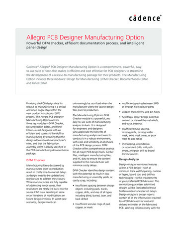
high-pass filter dSP techniquestxrxSerial link designers can incorporate measurement-based S-Parameter modelsin native Touchstone format. Combiningmeasured S-Parameter topology elementswith designed-in circuit elements allowusers to quickly do loss budget trade-offswith click of a mouse. This integratedS-Parameter support allows users to doquick multiple iterations of what-ifs bychanging the topology elements. de-emphasis Multi-tapCHANNEL ANALYSIS TO PREDICTBIT ERROR RATE (BER)Figure 4: Proven advanced macro-modeling capabilities for devices with pre-emphasis of receiver equalization—without sacrificing simulation performancefunctional physical prototypes. Thisadvanced technology offers integratedserial link design and analysis environment built on top of proven Allegro PCBSI capabilities.Multi-gigabit serial links are driven bytransmitters with multi-tap pre-emphasisand receivers with multi-tap equalization.These technological advances allow engineers to architect systems that havehigher performance and throughput.However, many of the EDA solutionsrequired to design these systems have notkept pace, leaving engineers forced touse disparate, stand-alone products.Allegro PCB SI GXL addresses the challenges typically created as systemdesigners work to provide ultra-highbandwidth for data transfer againstshrinking time-to-market windows.Another key challenge for multi-gigabitdesigners is to ensure that the timingand voltage margins are met. As traditional circuit simulators are limited toapproximately 1,024 bits of custom stimulus pattern length, the effect of intersymbol interference (ISI) is not adequatelymodeled. To accurately predict the eyeopening, engineers need solutions thatcan simulate stimulus patterns of 10 to100 million bits with various noisesources modeled and accounted for.www.cadence.comLOSS BUDGET TRADEOFFSTHROUGH INTEGRATEDS-PARAMETER SUPPORTDesigning multi-gigabit serial linksrequires capabilities that quickly and accurately model each element of the signal’spath. This is because at high frequenciesthe losses on a signal mount as the signaltravels through different discontinuitiessuch as vias, connectors, and differentlayers in one or more printed circuitboards. Ensuring that losses in criticalsignals are acceptable is an important stepin the design of multi-gigabit serial links.To accomplish this, Allegro PCB SI GXL letsengineers perform loss budget tradeoffsquickly and iteratively using S-Parameters.It also provides a way to change the MGHsignal’s topology and view expected lossthrough the system interconnect withinseconds. Allegro PCB SI GXL offers engineers an easy-to-use, highly integratedvirtual prototyping environment thatincludes built-in productivity capabilitiesfor MGH designs.MACRO MODELINGMacro modeling capabilities enable engineers to model and simulate MGHdrivers and receivers faster and moreaccurately—with simulation performanceimprovements of 20x to 400x over transistor-level simulation. (See Figure 4.)Channel analysis provides BER predictionthrough two approaches. First, it offersBER prediction through time domainbit-by-bit channel simulation. With thisapproach, users can simulate 10 to 100million bits in a reasonable amount oftime. Second, for channel compliance earlyin the design process users can use purestatistical analysis method to predict BER.CHANNEL SIMULATIONA channel simulation engine withinAllegro PCB SI GXL addresses the need forhigh-capacity, high performance bit-by-bitsimulation that can ensure timing andvoltage margins are met for MGH signals.This allows users to simulate millions ofbits very rapidly. On a typical PC/Windowsplatform, it can simulate 10,000 bits injust seconds, a million bits in an hour.Channel simulation is consistent with thetraditional circuit simulation methodology.Users can quickly overlay transistor levelsimulation results on top of channel analysis simulation results. (See Figure 5.)Systems company users can quicklydevelop meaningful configurations(“tap settings”) for a complex driver orreceiver. To determine optimal settings,designers get a recommendation for aspecific topology in seconds, savingweeks of simulation time. Users can injectdeterministic or random jitter, crosstalkfrom adjacent channels or signals anddata encoding to determine eye heightand width.C ade nce PCB Sig nal and Po wer Integrit y
IC companies can use channel simulationto quickly evaluate if a new device candrive legacy system company channelswith frequency offset, Duty CycleDistortion (DCD) what-if analysis to lookat sampling errors and determine howwell Clock and Data Recovery (CDR) circuit works in terms of jitter tolerance.CHANNEL COMPLIANCE THROUGHSTATISTICAL EYE GENERATIONMany systems companies, early in thedesign process, want to find out if anexisting channel can handle higher datarate transmitter and receiver to increasethe throughput of the channel. To figureout if a channel can be driven by higherdata rate transceivers, Allegro PCB SI GXLprovides a statistical eye generationengine. It provides a generic Feed BackEqualizer (FBE), an ideal Feed ForwardEqualizer (FFE), and an ideal DecisionFeedback Equalizer (DFE). Users canchange the number of taps and set thetap coefficients in these built-in models todo channel compliance through a purestatistical analysis. (See Figure 5.)INTEROPERABILITY OF ADVANCEDSERDES MODELS THROUGHALGORITHMIC MODEL SUPPORTDevices that operate above 5 Gbpsrequire algorithmic models to model theirbehavior. Channel analysis allows usersto plug-in executable algorithmic modelsfrom advanced SERDES IP Vendors. Plug-inexecutable models are provided in theform of dynamically linked libraries (DLLs).Channel analysis provides the uniquecapability of interoperability of advancedSERDES models through the ability to plug-in executable models from IP Vendors.Figure 5: Eye shrinks with number of bits in stimulus pattern. A good eye diagram is important form-accuratejitter, insertion loss, and BER predictionCONSTRAINT-DRIVENPCB DESIGN PROCESSCadence PCB SI technology works seamlessly with the constraint managementsystem of Allegro PCB Design Suite.Constraints derived through simulationcan be put into an Electrical ConstraintSet (EC Set) from within SigXplorer. TheseEC Sets can then be applied to other netsin the design through the constraintmanagement system. The constraintmanagement system is found in AllegroPCB SI, Allegro Design Entry HDL andAllegro PCB Design allowing designersto use constraints developed throughsimulation and exploration and enable aconstraint-driven physical layout process.(See Figure 6.)SpecificationsDesign implementationModel developmentand verificationSolution spaceexplorationESTIMATED CROSSTALK TABLESEstimated crosstalk tables generated fromAllegro PCB SI enable shorter designcycles and higher densities on the PCBdesign, possibly reducing end productcost through reduction of layers needed.It allows users to create estimated crosstalk tables to drive interactive and automatic routing to avoid crosstalk issues onthe board. Estimated crosstalk tables aregenerated for each unique driver, spacing,layer-to-layer combination, and simulationmode (fast, typical, or slow). With estimated crosstalk tables and a constraintdriven-PCB layout methodology, userscan shorten their design cycle time byavoiding crosstalk issues.Logic andtiming designOptimalconstraintsConstraint-driven FPConstraint-drivenplace and routePost-layout verificationConstraintdriven physicalimplementationFigure 6: Allegro PCB SI allows engineers to explore and develop optimum constraints with a constraint-drivendesign flowwww.cadence.comC ade nce PCB Sig nal and Po wer Integrit y
POST-LAYOUT DESIGNVERIFICATIONAllegro PCB SI is seamlessly integratedwith Cadence PCB editors. It allows usersto do post-layout verification right fromthe PCB editor. It also allows users todebug critical signals by extracting directlyfrom Allegro PCB design database without any translation. Users can simulate anet, a group of nets or all nets on theboard. Model assignment, models, aswell as all the simulation-derived constraints are embedded into the PCBdesign database.RULES CHECKING USINGEMCONTROLBy applying a combination of standardrules and user-defined rules, EMControlcan eliminate weeks of manual checkingand improve product quality and reliability.For a standard rule set, EMControl providescomprehensive, knowledge-based, designrule checking (DRC) for common EMIrelated placement and routing issues. Foruser-defined rules, EMControl allowscreation of custom rules that fit within acompany’s design guidelines. Importantly,these rules capture the high-speed design“experience” as customized rules, which inturn can be reused on future designs. TheEMControl module predicts farfield differential-mode radiated emissions in bothSigXplorer and the Allegro PCB SI floorplanner. It also allows for exploration ofdesign strategies required to keep radiation within acceptable levels. Near-fieldEMI analysis, available within the AllegroPCB SI floorplanner, can predict radiatedenergy immediately above the boardsurface. By analyzing near-field EMI patterns, designers can identify which portions of a routed trace are producing themost radiated energy and adapt thedesign accordingly.PCB DESIGN PLANNERAllegro PCB Design Planner is an optionthat allows users to develop effectiveconstraints for nets as well as components. Engineers can access thermal analysis, SI, and PI tools to derive constraintson nets and components. When used inconjunction with design creation tools, itwww.cadence.comallows engineers to specify design intentwith constraints embedded in the frontend design database.The PCB design planner option alsoincludes a floorplanning capability thatprovides a graphical view of the PCBdatabase allowing users to view and editthe PCB design. Designers can quickly andeasily evaluate the effects of differentplacement strategies on design behavior.MODEL DEVELOPMENTAND VERIFICATIONCadence PCB SI technology includes amodel integrity module that allowsdesigners to create, manipulate, andvalidate models quickly in an easy-to useediting environment. Device model formats supported include: IBIS 4.2 External Model support forVerilog -A, Cadence Spectre , HSPICE,Cadence eSpice models IBIS ICM package and connector models Mentor/Quad XTK Cadence Device Modeling Language(DML) Synopsys HSPICE transistor-level models(requires HSPICE simulator and license,which is not included with Allegro PCB SI) Spectre transistor-level models (availableon Sun Solaris, HP-UX, and Linux RHEL3.0 platforms only). This utilizes anintegrated and limited capability versionof the Spectre simulator, which isincluded with Allegro PCB SI XLA Spectre-to-DML conversion moduleassists in creating DML models fromSpectre simulation runs. With the outputof the Spectre simulation run, bufferoptions file, users can quickly create DMLmodels. Model integrity identifies V-I andV-T tables for typical, maximum, andminimum corner cases from the Spectrerun file. A proven, intelligent best-curvefitting algorithm provides an accurateDML model. An HSPICE–to-IBIS conversionmodule allows users to create IBIS modelsfrom HSPICE simulation runs.POWER DELIVERYSYSTEM DESIGNAllegro PCB PI is an option that can beadded on to Allegro PCB SI. This unique,integrated design and analysis environment takes the guesswork out of quantifying and controlling noise in powerdelivery systems. It allows users to focuson the design instead of struggling withdata translation issues between the CADsystem and the analysis engines. It integrates proven technology from SunMicrosystems into the Cadence designand analysis environment to address thepower delivery issues encountered inhigh-speed design.The PCB PI option embodies a methodology used to design and optimize frequency-dependent characteristics (supplypath impedance) of power distributionsystems in high-speed PCB design. Itallows users to do quick and easy iterations of “change-simulate-analyze.” TheCadence approach is rooted in the factthat a power distribution system’s impedance is frequency dependent and must beanalyzed and controlled over frequencyranges of interest. The maximum supplycurrent and the tolerated voltage rippleare used to derive the main power delivery system’s design parameter—the targetimpedance. Optimizing the target impedance over the frequency range in whichthe system is expected to operate yields apower delivery system without hot spots.The option offers a unique approach tothe actual designing of power distributionsystems. It takes the integrated approacha step further by making the debuggingof a problem as simple as “click andview.” Clicking on a waveform in thewaveform display window highlights thecorresponding region on the PCB andoffers a suggestion on the type and number of capacitors needed to addressthe problem. Results are displayed inthe waveform window. By having a PCBdesign editor integrated with this analysisenvironment, engineers can select andplace decoupling capacitors in the necessary areas, and then quickly seethe problem resolved.C ade nce PCB Sig nal and Po wer Integrit y
SETUP WIZARDGathers all the necessary pieces fordesign and analysis including board outline; layer stack-up; power plane shapes/power and ground plane pairs; DC netsassociated with the power planes; andcapacitor libraries.FREQUENCY DOMAIN ANALYSISCombines the right frequency domainanalysis engine with the proven, powerfulAllegro PCB SI and Allegro PCB Designenvironments. It simulates the problemin the frequency domain to quantify theimpedance of the power delivery systemacross the frequency range of interest.During simulation, it takes into accountthe entire power delivery system—VRM,bulk capacitors, bypass capacitors, andpower planes. It calculates the numberand values of decoupling capacitors andguides users in placing them for optimalresults. Users can perform single nodeanalysis early in the design cycle to seeif the number of capacitors selected canmaintain the target impedance over adesired frequency range. And, as capacitors are placed on the board, multi-nodesimulation, which takes into account thelocation of the capacitors on the boardand the mounted loop inductance, canbe easily run.VOLTAGE RIPPLES IN TIMEDOMAINEffectiveness of decoupling capacitorselection and placement can be verifiedin time domain.VRM EDITINGAn easy-to-use input inductance calculator and a target impedance calculatormake it simple to specify the allowedvoltage ripple and dynamic current tocompute the target impedance, andthe target impedance is shown in thesimulation results waveform window.The simulation waveform window displaysa target impedance line, which makes iteasy to know which regions of the PCBare crossing the target.www.cadence.comIC DIE AND PACKAGECHARACTERISTICSPCB PI option allows users to develop arealistic target impedance by includingIC/package inductance, and to assignpackage and die power delivery models toan arbitrary position on a two-dimensionalplane structure on the board to performmulti-node simulations. Users can provideIC switching current profile, on-die capacitance, IC/package sub-circuit for components on the board. Users also have anoption to provide IC/package inductanceif a sub-circuit for any of the componentsin not available. IC switching currentprofile can be obtained from IC companies. A two-port or a multi-port modelof a DC net of an IC/package can begenerated from IC/package design andanalysis tools.STATIC IR DROP ANALYSISUsers can quickly ensure power distribution system can provide sufficient currentto drive signals on the design throughStatic IR drop analysis. Static IR drop analysis takes into account the trace neck-down, swiss cheese effect created bycomponents with dense pin grid arrays(BGAs) as well reduction of availablecopper caused by trace routing on powerand ground planes. It will also take intoaccount vias that connect multiple groundplanes of the same net.Static IR drop analysis allows users to viewresults in a graphical voltage drop displayor view a report that shows voltage drop atany pin that is marked as a current sink.Users can also view relative and absolutevoltage drop at any point on the net.COMPLETE DESIGN AND ANALYSISENVIRONMENTPCB PI option offers a unique approach tothe actual designing of power distributionsystems. It takes the integrated approacha step further by making the debuggingof a problem as simple as “click andview.” Clicking on a waveform in thewaveform display window highlights thecorresponding region on the PCB andoffers a suggestion on the type and umber of capacitors needed to addressnthe problem. Results are displayed in thewaveform window. By having a PCBdesign editor integrated with this analysisenvironment, engineers can select andplace decoupling capacitors in the necessary areas, and then quickly seethe problem resolved.DESIGN-IN IPPORTFOLIOSTime to volume production for IC manufacturers depends on quick adoptionof new devices by systems companies.However, the combination of differingdesign environments, complex I/O structures, and multi-gigabit-speed datarates make new device simulation andimplementation into a PCB system a complex and expensive process.Innovative silicon design-in IP portfoliosfrom Cadence and key industry partnerstackle these issues. Using technologyavailable in the Allegro PCB SI design andanalysis environment, IC manufacturerscan help shorten their customers’ designin time on complex silicon devices byproviding an executable version of theirdesign guides in the form of high-speedsilicon design-in IP portfolios. These silicondesign-in IP portfolios contain ready-tosimulate topologies with pre-validatedmodels, layout constraints embedded in asample PCB file to enable constraintdriven layout flows, tutorials, documentation, scripts, and other utilities. Design-inIP portfolios allow engineers to accuratelysimulate PCB topologies with minimalsetup, enabling them to obtain accuratesimulation results 20 times faster thanwould have been possible without silicondesign-in IP.All design-in IP portfolios are available forCadence users to download from http://www.cadence.com/products/si pk bd/ic design in dt.aspxC ade nce PCB Sig nal and Po wer Integrit y
DDR2 DESIGN CHAINA methodology for designing system-levelDDR2 memory interfaces leverages IPfrom Altera, Micron Technology, andCadence. The methodology shown in theDDR2 Design-in IP Portfolio can be appliedto other high-speed source synchronoussignals as well.PCI EXPRESS DESIGN CHAINAs MGH serial interfaces become morecommon, many systems companies arechoosing to use the next-generation PCIbus—PCI Express. The PCI Express designchain provides an environment in whichsilicon vendors can communicate thedesign-in requirements for their devicesusing PCI Express. Systems companies areable to make trade-offs regarding the performance of member companies’ siliconwith respect to system requirements.CHIP SETS SPECIFIC DESIGN-INIP PORFOLIOSMENTOR BOARDSTATION FLOWCADENCE SERVICESAND SUPPORTAllegro PCB SI can be used in conjunctionwith the Mentor Board Station PCB designsystem to provide high-speed design andanalysis within a Mentor-based PCBdesign environment. Allegro PCB SI isused to perform high-speed analysis andto define the high-speed design rulesused to drive the Allegro PCB Router.Once the design has been placed androuted in accordance with the high-speedrules, the results are passed back to theMentor Board Station environment. Thisallows Allegro PCB SI and the Allegro PCBRouter to be used for high-speed designand analysis, while the existing BoardStation-based manufacturing outputprocess is used for committing the designto manufacturing. Cadence application engineers cananswer your technical questions bytelephone, email, or Internet—they canalso provide technical assistance andcustom trainingOPERATING SYSTEMSUPPORT INTEL IXP2800 NETWORK PROCESSORDESIGN-IN IP PORTFOLIOAllegro platform technology:For more information, contact your Intelrepresentative and ask for the hardwaredesign kit (HDK) for the IXP2800 networkprocessor. Linux XILINX VIRTEX II-PRO DESIGN-IN IPPORTFOLIOOrCAD technology: Cadence certified instructors teachmore than 70 courses and bringtheir real-world experience intothe classroom More than 25 Internet Learning Series(iLS) online courses allow you the flexibility of training at your own comput
Cadence allegro PCB Si l, Xl, and gXl Cadence orCad Signal explorer CADEnCE PCB SIGnAL AnD POwER InTEGRITy. www.cadence.com CADEnCE PCB SIGnAL AnD POwER InTEGRITy SoUrCe SynChronoUS, CoMMon CloCK Signal deSign SigXPlorer ModUle Cadence PCB SI technology contains a module for pre-route topology design and analysis even before a schematic is created (the SigXplorer module). This type of .