Transcription
Institutionen för systemteknikDepartment of Electrical EngineeringExamensarbeteImplementation of CAN Communication Stack inAUTOSARExamensarbete utfört i Datorteknikvid Tekniska högskolan vid Linköpings universitetavJohan Alexandersson och Olle NordinLiTH-ISY-EX-ET–15/0440–SELinköping 2015Department of Electrical EngineeringLinköpings universitetSE-581 83 Linköping, SwedenLinköpings tekniska högskolaLinköpings universitet581 83 Linköping
Implementation of CAN Communication Stack inAUTOSARExamensarbete utfört i Datorteknikvid Tekniska högskolan vid Linköpings universitetavJohan Alexandersson och Olle rs Nilssonisy, Linköpings universitetSimon TegelidÅF ConsultingExaminator:Anders Nilssonisy, Linköpings universitetLinköping, 15 juni 2015
AbstractIn the automotive industry today, embedded systems have reached a level of complexity which is not maintainable with the traditional approach of designingautomotive embedded systems. For this purpose, many of the world’s leadingautomotive manufacturers have formed an alliance to apprehend this problem.This has resulted in AUTOSAR, an open standardized architecture for automotiveembedded systems, which strives for increased flexibility and safety regulations.This thesis will explore the possibilities of implementing a CAN Communicationstack using the AUTOSAR architecture and its corresponding methodology. As aresult of this thesis, a complete AUTOSAR CAN communication stack has beenimplemented, as well has a simulator application with the purpose of testing itsfunctionality.iii
AcknowledgmentsFirst and foremost, we would like to thank Simon Tegelid and Magnus Carlssonat ÅF, for endless support whenever needed. We would also like to thank Anders Nilsson at ISY for consistently being available with good advice. Additionalaccolades go out to friends and family.Linköping, June 2015Johan Alexandersson and Olle Nordinv
ContentsNotation1 Introduction1.1 The Company1.2 Background .1.3 Purpose . . . .1.4 Limitations . .1.5 Equipment . .ix.1112222 Theory2.1 AUTOSAR . . . . . . . . . . . . . . . .2.1.1 Layered Software Architecture2.1.2 Basic Software Layer . . . . . .2.1.3 BSW modules . . . . . . . . . .2.1.4 CAN Communication Stack . .2.1.5 Application Layer . . . . . . . .2.1.6 Runtime Environment . . . . .2.2 Controller Area Network . . . . . . . .2.2.1 Layers . . . . . . . . . . . . . .2.2.2 CAN Messages . . . . . . . . . .55678815171919193 Method3.1 AUTOSAR Methodology . . . . . . . . . . . . . . .3.1.1 BSW configuration . . . . . . . . . . . . . .3.1.2 Develop System Description . . . . . . . . .3.1.3 Design System . . . . . . . . . . . . . . . . .3.1.4 Develop Application Software Components3.1.5 Build ECU Software . . . . . . . . . . . . . .3.1.6 Modeling approach . . . . . . . . . . . . . .3.2 Development Tools . . . . . . . . . . . . . . . . . .3.2.1 Arctic Studio . . . . . . . . . . . . . . . . . .3.2.2 HALCoGen . . . . . . . . . . . . . . . . . .3.2.3 Code Composer Studio . . . . . . . . . . . .232324242425252526262627.vii.
viiiContents3.2.4 PyQtGraph . . . . . . . . . . . . . . . . . . .3.2.5 PyQt . . . . . . . . . . . . . . . . . . . . . .3.3 Project Method . . . . . . . . . . . . . . . . . . . . .3.3.1 Pre-Study . . . . . . . . . . . . . . . . . . .3.3.2 AUTOSAR Development . . . . . . . . . . .3.3.3 BSW Configuration . . . . . . . . . . . . . .3.3.4 Develop System Description . . . . . . . . .3.3.5 Develop Application Software Component .3.3.6 Design System . . . . . . . . . . . . . . . . .3.3.7 Build Ecu Software . . . . . . . . . . . . . .3.3.8 Simulator Application Development . . . .3.3.9 Testing . . . . . . . . . . . . . . . . . . . . .2727282830304042444647514 Results4.1 ECU . . . . . . . . . . . . . . . . . . . . . . . . . . . . . . . . . . . .4.2 Simulation . . . . . . . . . . . . . . . . . . . . . . . . . . . . . . . .5353555 Discussion5.1 Analysis of the results5.2 Method . . . . . . . .5.3 Conclusions . . . . .5.3.1 Future work .7373747474.List of Figures76A Appendix A: Flowcharts81Bibliography85
ix
nACKAP IAU T OSARBSWCANCAN I fCCSCOMCRCDI ODLCECUECU CECU ME/EGI OGU IHWIDI DEI P DULP DUMCALMCUOSP DUP DU RRECRT ERT RSWSW CT ECAcknowledgementApplication Peripheral InterfaceAutomotive Open System ArchitectureBasic Software LayerControl Area NetworkCan InterfaceCode Composer StudioCommunicationCyclic Redundancy CheckDigital Input/OutputData Length CodeElectronic Control UnitECU ConfigurationECU ManagerElectrical/ElectronicGeneral-Purpose Input/OutputGraphical User InterfaceHardwareIdentifierIntegrated Development EnvironmentInternal Layer Protocol Data UnitData Link Layer Protocol Data UnitMicrocontroller Abstraction LayerMicrocontroller UnitOperating SystemProtocol Data UnitPDU RouterReceive Error CounterRuntime EnvironmentRemote Transmission RequestSoftwareSoftware ComponentTransmit Error Counter
1Introduction1.1The CompanyThis thesis will be conducted at ÅF Consulting in Linköping. ÅF Consultingis a Swedish consulting company with over 7000 employees all over the world[3]. The company covers many different areas including for example industry,infrastructure and technology. Our thesis will be carried out at ÅF’s technologysection.1.2BackgroundIn the automotive industry there has always been trouble with integrating software into different hardware components. In order to solve this problem, an international open source standard was developed in collaboration between manyof the world’s leading automotive companies. This standard was to be named AUTOSAR and its purpose is to improve the compatibility between different ECUs,regardless of hardware and manufacturer. At ÅF there has been a project with asmall electrical car model type Sinclair C5. This project has consisted of upgrading the hardware and developing some software for controlling the car. This hasbeen done in a traditional manner with no regard to the AUTOSAR specifications.One of the components of this vehicle is a control unit which controls the different units of the vehicle for example the motor driver. The control unit basicallyserves as a CAN-hub, sending and receiving messages to and from other ECUs inthe vehicle. This thesis will explore the possibilities of implementing this controlunit in a system based on the AUTOSAR system architecture.1
211.3IntroductionPurposeThe purpose with this thesis is to implement a platform for CAN-communicationusing the AUTOSAR system architecture, going through all software layers to agraphical interface on the PC. The main focus with this thesis will be the configuration of the BSW modules within AUTOSAR, as well as the implementationand modelling of the SWCs. The platform needs to be compatible with the CANnetwork of the Sinclair, which means it needs to be able to process 36 differenttypes of CAN IDs, and also to be able to send and receive messages with a datalength of 5 bytes. In specific, the following needs to be investigated: How to configure the Basic Software Modules in order to achieve CAN communication. How to create software components with the task of reading, interpreting,and writing CAN signals. How to set up the AUTOSAR Runtime Environment, which connects thesoftware components with the Basic Software Modules How to send and receive signals exceeding limits on internal signal lengths. How to create a GUI with the task of sending and receiving CAN signalsand displaying these signal values on a plot.1.4LimitationsThe following limitations are set for this project: The actual control unit software for the Sinclair will not be integrated inAUTOSAR software. Instead, a CAN communication stack will be implemented which will leave room for future integration of the control unitsoftware. Ethical aspects of any kind will not be discussed in this thesis.1.5EquipmentIn this thesis, the following equipment and software will be used: ArcCore Arctic Studio– An IDE based on Eclipse where AUTOSAR embedded applications aredeveloped. ArcCore Arctic Core– An embedded platform based on the AUTOSAR specification.
1.5Equipment Kvaser Leaf Light HS v2– USB Can Adapter Texas Instruments TMDX570LS20SMDK– A development kit for Cortex ARM-R MCUs3
2Theory2.1AUTOSARGiven the increased complexity in automotive embedded systems today, the automotive industry has seen a need of an open industry standard for automotiveelectronic architecture. This has resulted in many of the world-leading automotive companies forming a partnership, which goal is to establish this standard.The standard, as well as the partnership, is called AUTOSAR, which stands forAutomotive Open System Architecture. The partnership was founded in 2002,initially by BMW, Bosch, Continental, DamienChrysler, and Volkswagen, withSiemens joining the partnership shortly thereafter. [6]According to the AUTOSAR website, the motivation for establishing the standard are the following points: "Management of E/E complexity associated with growth in functional scope" "Flexibility for product modification, upgrade and update" "Scalability of solutions within and across product lines" "Improved quality and reliability of E/E systems"[5]The goals with AUTOSAR are the following: "Fulfillment of future vehicle requirements, such as, availability and safety, SWupgrades/ updates and maintainability" "Increased scalability and flexibility to integrate and transfer functions" "Higher penetration of "Commercial off the Shelf" SW and HW componentsacross product lines"5
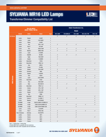
62Theory "Improved containment of product and process complexity and risk" "Cost optimization of scalable systems"[5]2.1.1Layered Software ArchitectureSince one of the main goals of AUTOSAR is to provide flexibility, a layered software architecture has been conceived. It is mainly divided up in three layers,shown in Fig. 2.1 below.Figure 2.1: Layered Software Architecture2.1.1.1Basic Software LayerThe first layer, starting from the bottom, is called the Basic Software Layer (BSW).The purpose of this layer is to provide an hardware independent abstraction toother layers. This means that the BSW layer needs to interact with the microcontroller itself, making it hardware dependent. Due to this, the BSW layer needsto be implemented depending on what kind of hardware is used. The BSW layercontains standardized infrastructure for example the communication stack, thememory stack, diagnostic services, and the operating system. [7]2.1.1.2Runtime EnvironmentThe next layer in the architecture is the Runtime Environment, commonly abbreviated RTE. The purpose of this layer is to abstract the application layer fromthe BSW layer. In practice, this basically means that the RTE provides the Application Layer and the Basic Software Layer with a common interface, providinginteraction between the two layers. [7]
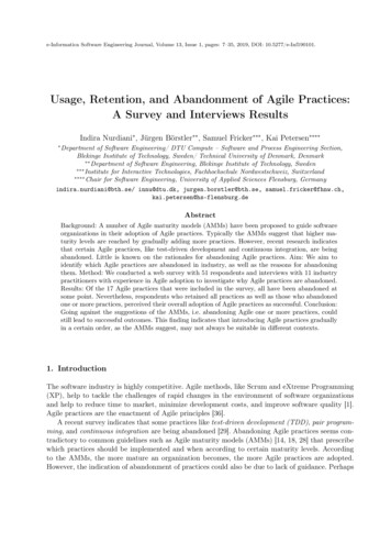
2.17AUTOSAR2.1.1.3Application LayerThe final layer is the Application Layer. This layer contains application moduleswhich are called Software Components (SWC). These contain software for thesystem which is completely hardware independent. This means for example thatan SWC of an ECU with one kind of hardware can interact with an SWC of anECU with another kind of hardware with great ease. [17]2.1.2Basic Software LayerThe Basic Software Layer is furtherly divided into sublayers, as shown in Fig. 2.2below. Explanations for layers not used in this thesis are excluded.Figure 2.2: Basic Software Layer2.1.2.1Microcontroller Abstraction LayerThe Microcontroller Abstraction Layer (MCAL) is the layer at the bottom of theBSW layer. The modules in this layer interact directly with the MCU. The purposeof this layer is to make layers above this layer hardware independent, as this layerprovides functions defined by the AUTOSAR specification. Given the fact thatthis layer interacts directly with the MCU, this layer is hardware dependent. [7]2.1.2.2ECU Abstraction LayerThe next layer in the BSW layer is called the ECU Abstraction Layer (ECUAL).This layer provides an interface of the drivers found in the MCAL layer to thelayers situated above the ECU Abstraction Layer. Drivers for external devicessuch as CAN transceivers are included here as well. [7]
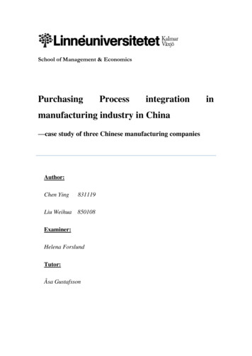
82.1.2.32TheorySystem Services LayerThe upper layer in the BSW layer is called the System Services Layer. This layerprovides functions for the Application Layer, hence its position in the hierarchy.It contains modules for the operating system, communication services, memoryservices, ECU state management, and so on. [7]2.1.3BSW modulesThis section explains some of the modules in the BSW layer, mainly the onesused in this thesis. These modules are divided into functional groups, which areshown in Fig. 2.3 below.Figure 2.3: BSW Functional Groups2.1.4CAN Communication StackThe purpose of the CAN communication stack is to accommodate a completeCAN communication interface for the Application Layer. This means that SWC’sneed to pay no regard to identifiers, data lengths, bit timing and so on, this isall handled by the communication stack. It is comprised by several modulesfulfilling this purpose, which are shown in Fig. 2.4 below. [7]
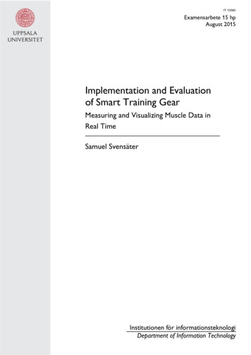
2.19AUTOSARFigure 2.4: CAN communication stack2.1.4.1Protocol Data UnitProtocol Data Unit (PDU) is a term which describes the data of a specific communication protocol. Signals sent in a CAN communication stack are grouped inCAN PDUs which in turn are mapped to CAN frames. A CAN frame is in factalso a PDU but on the link layer, and might be referred to as an L-PDU whilethe CAN PDUs operating on the higher layers in the stack are referred to as IPDUs. These signal paths of the PDUs are routed between different modules ofthe CAN communication stack. The signal paths are routed from the COM module, through the PDU router, to the CAN interface, providing the COM modulewith means to initiate CAN data transmission, as well as receiving data at such
102Theoryan event. All communication above the PDU router is passed through I-PDUS aswell as the communication to and from the CANIf module. However, below theCANIf module, the communication is via L-PDUs. The connection of the PDUpaths is shown in Fig. 2.5 below. [18]Figure 2.5: PDU connections within the CAN communication stack
2.111AUTOSARFigure 2.6: Example of communication with PDUIn the Fig. 2.6 above, an example of the whole process of communicationthrough I-PDUs is shown. In this case we have an example of CAN data beingsent. Initially, the COM module initiates the communication process by callingthe PduR TRANSMIT() function. Due to the routing tables of the PDU routerthat have been previously configured, it is known that this data’s destinationis the CAN bus. Thus, the CanIf Transmit() function is called. Once the CANinterface has received an acknowledgement bit from the CAN receiver it willcall the PduR CanIfTxConfirmation() function, and the PDU router will call theCom TxConfirmation().2.1.4.2CAN DriverThe CAN Driver is situated at the bottom of the CAN communication stack,which is depicted in Fig. 2.4 above. The CAN driver module provides hardware access to the upper layers within the communication stack. To do this, itprovides the Communication Hardware Abstraction layer with a standardizedAPI.[18] The CAN Driver includes several hardware objects, which are used tocontrol the transmission and reception of L-PDUs. [9]2.1.4.3CAN InterfaceNext in order in the CAN communication stack is the CAN interface module,CANIf. The CANIf module is located between the Communication Services Layerand the Communication Drivers Layer in the CAN communication stack, as isseen in Fig. 2.4. As well as controlling the initialization of the CAN driver module, it also provides the CAN driver module with notification services, such as
122Theorythe function CanIf RxIndication for reception, as well as CanIf TxConfirmationfor transmission. The CANIf module acts as a user of the CAN driver module’shardware objects for reception and transmission. This makes the CANIf module independent of hardware, since the CANIf module is not accessing hardwarefunctionality directly, but instead using the CAN Driver module. [10]2.1.4.4PDU RouterFurther up in the CAN communication stack is the PDU router. The PDUR module provides routing paths within the CAN communication stack. This way, thedestination and the source of a PDU is specified. Receiving I-PDUs are routedwith the CANIf module as the source, and to an upper module in the Communication Services layer of choice as the destination. Transmitting I-PDUs are donein the reverse approach, and are routed with a Communication Services Layermodule of choice as the source, and the CAN Interface Layer as the destination.[13]2.1.4.5COMThe COM module is placed at the top of the CAN communication stack. TheCOM module handles all of the signals going to and from the RTE, as sender andreceiver signals. These signals are each referring to an individual I-PDU for thecommunication throughout the BSW layer. [11]2.1.4.6Operating systemThe OS module is part of the system services layer. The OS provides an interfacefor startup as well as the shutdown of the system. Moreover, the OS also managesthe activation/termination of tasks and the execution of these in a scheduled order based on priority. There are two types of tasks namely extended task as wellas basic task. As can be seen in Fig. 2.7 below the extended task consists of fourdifferent states, Wait state, Running state, Ready state and Suspended state. Thetask changes state depending on state transitions. The state transitions are thefollowing: Preempt, Start, Terminate, Wait, Release, and Activate. Preempt isa state transition where the task makes a transition from Running to Ready, itoccurs when the OS task scheduler starts another task with higher priority. TheStart transition occurs when a task is in the Ready state and is being selected bythe task scheduler. The Termination transition occurs when a termination of taskfunction is called, for example TerminateTask(), the task makes a transition intothe suspended state. The Wait transition occurs in extended task when the task isin the Running state but needs to wait for an event to occur. As for the activationof an extended task, it can be done for example through the usage of alarms, thiswill cause the task to enter the Ready state. These alarms could for example beset to trigger a specific event for example an event telling that a specific resourceneeded by an extended task is available. That event will trigger the extendedtask to go from the waiting state into the ready state and causes the task to beexecuted, this step transition is called Release. [22]
2.113AUTOSARFigure 2.7: States of an extended taskThere are also basic tasks which are not using events to be triggered, they aretherefore lacking the "Wait" state. This can be seen in the Fig. 2.8 below. Thesetasks will instead be activated via the triggering of an alarm or by being activatedvia other tasks. Similar to the transitions in the extended task, the basic task usesmost of them except for the ones regarding the Wait state. [22]Figure 2.8: Illustration of a basic taskIn the Fig. 2.9 below, there is an example of the execution of tasks based onpriority.
142TheoryFigure 2.9: Task prioritiesGiven these specifications the tasks will be executed in the following order:A - B - C. However, since A will occur once again during the execution of C,A will be executed and interrupt C. This is due to the priority between the tasks,which can be seen in the Fig. 2.10 belowFigure 2.10: Example of Task Execution2.1.4.7ECU managerThe ECU manager controls the initialization of the OS, as well as the initialization of the MCU-drivers for example the DIO-drivers, CAN-drivers, and the Portdrivers. First and foremost all the drivers necessary for the OS functionality areinitialized and there on after, a callout for the initialization of additional driversis used, an example of this is shown below. Moreover, the ECUM also controlsthe shutdown of the OS as well. The startup sequence of the ECUM is shown inFig. 2.11 below.[12]
2.115AUTOSARFigure 2.11: EcuM startup sequence2.1.5Application LayerThe purpose of the application layer is to provide the actual functionality of thesystem. This is done through the usage of SWCs, which are components containing software. An example of such a component is displayed in Fig. 2.12 below.[14]Figure 2.12: Example of software component
162.1.5.12TheoryPortsFig. 2.12 shows an example of the port setup of an SWC. These ports are used toconnect the SWC to other instances. The most basic type of ports are the senderand receiver ports. These are used to provide means of data transmission between different SWCs, or between the SWC and the RTE. Sender/Receiver portsare depicted as squares with black arrows. For example, in Fig. 2.12 the port"SeatSwitch" is a receiver port, and the port "DialLED" is a sender port. A receiver port must have a corresponding sender port and vice versa. This is shownin Fig. 2.13 below.Figure 2.13: Example of sender/receiver interface
2.117AUTOSARAnother common type of port interface is the Client/Server. These ports areused when the SWC needs to use a function (in the application layer these areknown as runnables) contained within another SWC or a function of a BSW module. The client port (HeatingElement in the Fig. 2.12) is the port requesting afunction to be called, and the server port (Setting in the Fig. 2.12) is the portbelonging to the entity who provides the function. Below is a Fig. 2.14 whichshows Client/Server connections between different SWCs.[14]Figure 2.14: Example of client/server interface2.1.5.2RunnablesThe functional implementation of an SWC is known as a "runnable entity", orsimply a runnable. An SWC may contain a single runnable, as well as a largernumber of runnables. A runnable contains a sequence of instructions in a codinglanguage of choice.[15] The activation of a runnable is done by setting an event,and there are several different types of these events. If the runnable is invokedby a timingEvent, the runnable will be activated periodically with a given timeperiod. A runnable can also be invoked by a dataReceivedEvent, which means thatthe runnable will be activated when data has been received on a given receiverport of the SWC. As described in the previous section, the runnable can also beinvoked by a Client/Server interface, in this case the server port will produce anoperationInvokedEvent which will activate a runnable set to a client port. Theseare only a handful of the events available in AUTOSAR.[14]2.1.6Runtime EnvironmentIn order for an SWC in the application layer to communicate with other SWCsand BSW modules, a common interface for the Application Layer and the BasicSoftware Layer is required. The RTE was conceived for this purpose.[21] Anexample of how the RTE is used with the other modules is presented in Fig. 2.15below.
182TheoryFigure 2.15: Runtime Environment interaction with other modulesIn the Fig. 2.15 above, it is shown how the RTE is connected to different modules. It is implemented in the form of a bus, so each SWC can access any softwaremodule in the top layer of the BSW layer. This also enables the communicationbetween the SWCs. In order to implement the RTE, a tool called the "RTE Generator" is used. This is a configuration tool which generates code correspondingto configurations set by the user. This configuration step involves mapping SWCrunnables to OS tasks and events. The code generated includes functions used bythe SWC runnables to call functions of modules in the BSW layer. To illustratethis, a code example is shown below.uint32 message 0xFFFF;void Runnable {Rte IWrite Runnable SenderPort data(message);}The runnable in the code example uses a function generated by the RTE towrite a hexadecimal value 0xFFFF to a port of the SWC. This port is affiliatedwith an internal signal specified in the communication stack. For example, if thesignal is specified to be connected to the CAN interface, this function will sendout a CAN message on the CAN bus
2.2Controller Area Network2.219Controller Area NetworkThe controller area network is a communication protocol for serial transfer ofdata. It has been used ever since its introduction 1985. Today with the increasingamount of electronic devices in cars, one of the biggest concerns is establishingsecurity and to be able to as easily as possible integrate electronics into the car. Today when integrating electronic circuits into the car, the CAN Network becomesattractive as a solution to minimize the wiring required for the devices to be ableto function correctly. This saves a lot of space, and makes it cost-effective.[16]CAN is divided into three different layers, the object layer, transfer layer andthe physical layer which will be explained a little more thoroughly below.[16]2.2.1Layers2.2.1.1Object layerThe CAN object layer’s task is to decide which messages are to be transmittedas well as which messages received are to be used. This is also called messagefiltering. [16]2.2.1.2Transfer layerThe transfer layer’s task is to perform arbitration to check priority of messages, aswell as the fault confinement with the three different states of a node (Active, Passive or bus off). Moreover it also controls error detection and message validation.Furthermore the transfer layer also controls the transfer rate and the bit timingsettings. It also checks if the CAN bus is free to start a new transmission of amessage from the object layer or whether a reception of a message to the objectlayer has just been started.[16]2.2.1.3Physical layerThe physical layer is defined as how the communication between two devices ormore should be handled with regard to the physical medium used as connectionbetween these devices. [23]2.2.2CAN MessagesThere are four different types of CAN messages: remote frames, data frames, error frames and overload frames. These frames will be described below.[16]2.2.2.1Data frameThe data frame consists of seven different fields with the objective to carry datafrom a transmitter to a receiver. The first field of a data frame is named "start offrame" which contains a single logical bit set to ’0’ (dominant bit). This indicates
202Theorythat either a new data frame or a new remote frame is on the bus.[16] Fig. 2.16below shows the fields of the Data frame.Figure 2.16: Fields within the Data frameNext, the data frame consists of an arbitration field, which is made up of anidentifier field as well as an RTR-bit. The identifier field in the arbitration fieldserves as either an 11 or 29 bit identifier for the content of the message. Thisis known as either a standard identifier or an extended identifier, respectively.Commonly, the standard identifier format is used. The identifier is then used bythe nodes in the network to decide if they should use the information or not. Theidentifier also contains the necessary information on how to prioritize messageswhich are simultaneously sent out on the CAN bus. This is done by comparingthe messages bitwise and the one with the lowest identifier gains arbitration. TheRTR-bit is set to dominant to indicate that it’s a data frame, if it’s set to ’1’ (recessive) it instead indicates that it’s a remote frame. [16] A Fig. 2.17 illustrating thearbitration field is shown below.Figure 2.17: Illustration of the arbitration fieldAfter the arbitration field, the data frame consists of a control field which ismade up of six bits. Two reserved bits are set to dominant. Thereafter there are
2.2Controller Area Network21four bits regarding the length in bytes of the data to be transmitted, 0 up to 8bytes. [16] Fig. 2.18 located below is illustrating the control field.Figure 2.18: Illustration of the control fieldThereafter the data frame consists of a field called data field. It is made up of8 bits, with the eight bit being the most significant, bit and can contain up to 64bytes of data. [16]Further on we have the CRC field which consists of a CRC sequence as wellas a CRC delimiter. The CRC sequence is used for error detection. It performs aCRC on the data sent or received and compares the received CRC-value with anexpected value. If these values differ, the CRC has detected a data error and willeither reread the data or request a new transmission. The last bit of the CRC fieldis called the CRC delimiter, which is a single recessive bit. [16] Fig. 2.19 belowdepicts the CRC field.Figure 2.19: Illustration of the CRC fieldThereafter the data frame is made up of an ACK field which consists of twobits. The ACK slot can either be dominant or recessive. If it’s a node transmittingdata, the ACK slot will consist of a recessive bit. When a node receives the sentframe, the receiver verifies the integrity of the frame and sends a dominant bitduring the ACK part of the frame if it was received correctly. The last bit of the
222TheoryACK field is called the ACK delimiter, which is a single recessive bit. [16] Fig.2.20 below illustrates the ACK field.Figure 2.20: Illustration of the ACK fieldFinally, the data frame consists of a field named "end of frame" which is madeup of seven recessive bits. This will indicate the end of the data
Kvaser Leaf Light HS v2 - USB Can Adapter Texas Instruments TMDX570LS20SMDK - A development kit for Cortex ARM-R MCUs. 2 Theory 2.1AUTOSAR Given the increased complexity in automotive embedded systems today, the au-tomotive industry has seen a need of an open industry standard for automotive