Transcription
EECT6326 Cadence Virtuoso 6 SetupFall 2022Contents1 NoMachine Setup12 One-Time Cadence Virtuoso Setup63 Every Time You Launch Cadence Virtuoso4 How to Use Cadence Virtuoso4.1 Making a Schematic Cell View4.2 Adding Instances and Wires . .4.3 Running a Simulation . . . . .4.4 Parametric Sweeps . . . . . . .4.4.1 Secondary Sweeps . . .10.5 Example Project: Amplifier1.12121415171819NoMachine SetupNote: If you have already set up NoMachine on your computer for a different class, you can skip this section.This refers to the connection to the NoMachine server itself - even if you have Cadence Virtuoso set up foranother class, you will need to follow the steps in the other sections to set up Cadence Virtuoso for this class.1. Download the NoMachine client from https://www.nomachine.com/download and run the installer onyour computer. It is available for Windows, Mac, and Linux. You may have to restart your computerafter the installer finishes.2. For the following steps, make sure your are connected to either: CometNet if you are on campus The UTD VPN if you are off campus. See https://www.utdallas.edu/oit/vpn/ for instructionson setting up the UTD VPN.Note that you will need to be connected to CometNet or the UTD VPN every time you connect toNoMachine, not just for setup.1
3. When you first launch NoMachine, continue past the welcome screen. Then, click on Add to add anew connection.4. In the Address tab, set the following:(a) Give your connection some useful Name, such as UTD NoMachine .(b) Type in engnx.utdallas.edu as the Host.(c) Make sure that the Port is 4000 and that the Protocol is NX5. Then, click Connect2
6. The first time you launch the connection, you may see a message asking to verify the host authenticity.Click Yes to continue.7. Enter your Net ID and password when prompted. If you wish, you can save the password so you don’thave to type it in every time you connect. Click Login to continue.3
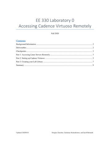
8. If you do not already have a virtual desktop open, you will need to create one. If you see a screen asbelow, click on New Desktop. Your screen may already look like the one in the next step - if so,move on to creating the new desktop.9. We will now create the new desktop. Either the GNOME or KDE desktop environments should befine. Personally, I prefer KDE, so I will click on Create a new KDE virtual desktop, then clickthe Create button.10. The next several screens will show you some ways to control NoMachine. You can read through themand click OK. If you want, you can select Don’t show this dialog anymore if you do not want tosee the controls instructions every time you log in.4
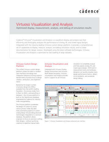
11. You should now see the NoMachine desktop, which looks like the picture below if you chose the KDEdesktop environment. Any windows you open in the virtual desktop will stay open as long as thevirtual desktop does, even if you disconnect from NoMachine.5
2One-Time Cadence Virtuoso SetupNote: This section only needs to be done once, not every time you want to use Cadence Virtuoso. You willneed to do this even if you have Cadence set up for another class, since you will be using a particular modelfile for the simulations in this class.1. Connect to your NoMachine desktop. We will need to launch the terminal emulator, called Konsolein KDE. In the bottom left menu, click on Red Hat icon, then click on Terminal. Note that there isalso a shortcut to launch the terminal in the lower right part of the screen as well. If you are using theGNOME environment, you may need to search for the Terminal application.2. Type the command cd and hit enter to make sure that you are in your home directory.3. Type the command tar zxvf /proj/cad/startup/EE4340.tar.gz and hit enter to untar that file intoyour current directory. You can check that the command worked by typing the command ls andhitting enter to see if a directory called EE4340 was created.6
Now we will create a library in which you can create all of your files for this class.1. First, in the terminal, type the command cd EE4340 and hit enter to change to the Cadence directoryfor this class.2. We need to replace the profile to be for the latest version of Cadence. To do this, type rm -f profile.ic-5and hit enter to remove the old profile. Then, typecp /proj/cad/startup/profile.ee7325 ./profile.ic-6 to copy the Cadence 6 profile to your directory witha new name.3. Then type the command source profile.ic-6 and hit enter to setup your environment variables.4. Type virtuoso& and hit enter to launch the command interpreter window (CIW). If you get a What’snew in IC6 Overview window, you can close it.5. Now open the Library Manager by clicking on Tools, then Library Manager.7
6. Click on File, then New, then Library.7. Give your library a useful name like EE4340 and click OK8. Select Do not need process information and click OK. Note that the window might open upbehind others.8
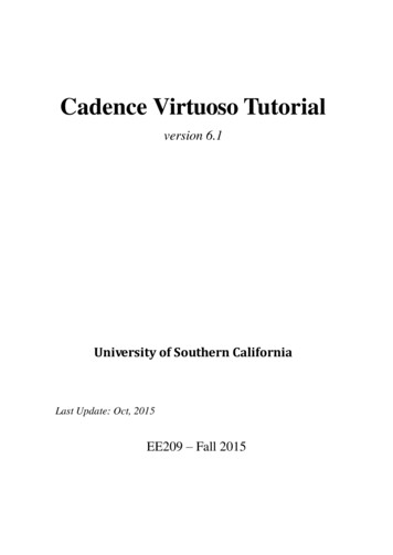
9. You should now see your library in the Library Manager. This is where you will create all yourschematics for this class.9
3Every Time You Launch Cadence VirtuosoNote: These steps are to launch Cadence Virtuoso if it is not currently open. If you already have Cadenceopen for this class and can see your Library Manager, you do not need to do this.1. Connect to your NoMachine desktop. We will need to launch the terminal emulator, called Konsolein KDE. In the bottom left menu, click on Red Hat icon, then click on Terminal. Note that there isalso a shortcut to launch the terminal in the lower right part of the screen as well. If you are using theGNOME environment, you may need to search for the Terminal application.2. Run the following commands to change to the Cadence directory for this class, set up the environment,and launch the command interpreter window (CIW).cdcd EE4340source profile.ic-6virtuoso&10
3. Open the Library Manager by clicking on Tools, then Library Manager.11
4How to Use Cadence VirtuosoIn this section, we will make a schematic cell view and look at some components that could be useful in thisclass. Note that you don’t have to make all the things described in this section - it is mostly here for yourreference.4.1Making a Schematic Cell ViewEach time you want to make a new schematic, do this:1. If Cadence is not launched, launch Cadence as shown in Section 3.2. In the Library Manager, click on File, then New, then Cell View. Note that the window may appearbehind the Library Manager.3. In the New File window, make sure that your library for this class is selected in the Library dropdown.Then give your cell some useful name - in this case, I will call it test cell . Finally, make sure thatthe Type is set to Schematic - the other fields, such as View and Open With, should be setautomatically as long as the Type is Schematic.12
4. If you get a Next License window giving you a warning, click Yes to continue.5. You should now see a view that looks like this:13
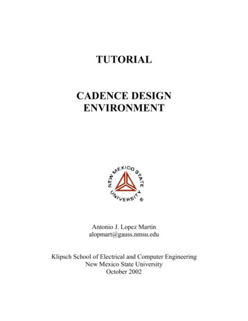
4.2Adding Instances and WiresTo add an instance of a transistor, power supply, or other component to your circuit, use the Add Instancedialog. You can access it in the menu Create Instance; through the Create Instance button in thetoolbar (the transistor with the green plus by it); or by using the shortcut i .Basically all instances we will need for this class can be found in analogLib. Select that as the Library,then you can select the cell you want to add. Here are a few useful ones for this class: nmos4 - An NMOS device with the body terminal explicitly shown. Use this whenever you want anNMOS transistor in your circuit. Set the Model name to NMOS , then set the Width and Lengthas desired. The minimum length is 240nm, but most HW assignments will tell you what length to use. pmos4 - A PMOS device. It has the same fields as nmos4, except that you should set the Modelname to PMOS . vdc - A DC voltage source. You can set the DC voltage field to set the DC voltage. You can alsouse this as an AC voltage source by setting the AC magnitude field. Note that if you use it as anAC voltage source, it produces a small signal that doesn’t change any bias points - it’s not a numberof volts it applies. vpulse - This is useful for transient simulations. Set the Voltage 1, Voltage 2, Period, Rise time,Fall time, and Pulse width as needed idc - A DC current source. Has the same fields as vdc, but is in amps rather than volts gnd - Represents ground. You will need at least one in your circuit if you’re going to run a simulation. vdd - Represents VDD . Note that it does not provide any power by itself - you will still need to connectit to a DC voltage source. See the circuit in the example project to see how to use vdd. cap - A capacitor. Set the Capacitance field. res - A resistor. Set the Resistance field. vcvs - A voltage controlled voltage source. Set the Voltage gain field. You may also want to set theMaximum Output Voltage and Minimum Output Voltage fields to make sure the output isn’thigher than VDD or lower than ground.14
Note that you can type the values for different fields as a number, with exponents, or with common SIprefixes. Some examples: A 500 mV voltage source could be specified as 0.5 , 5e-1 , or 500m A 1 pF capacitor could be specified as 1e-12 pr 1p A 1µm transistor width could be specified as 1e-6 or 1u A 350 nm transistor length could be specified as 3.5e-7 , 350n , or 0.35uOnce you have an instance selected, you can place as many as you want, then press the escape key tostop placing instances. You can edit the properties of an instance by clicking on it, then pressing q .To add a wire, you can go in the menu Create Wire (narrow); through the Create Narrow Wirebutton in the toolbar (the thinner zigzagged wire); or by using the shortcut w . Make sure to use narrowwires and not wide wires. You can place as many wires as you like, then press the escape key to stop placingwires.To give a wire a useful name, you can go in the menu Create Wire Name.; through the CreateWire Name button in the toolbar (the wire with abc written above it); or by using the shortcut l . Typeas many wire names as you like in order, separated by spaces, then click on the wires you want to name inthe same order. Then press the escape key to stop.4.3Running a SimulationIn order to run simulations, you can launch the Analog Design Environment in Launch ADE L. If youget a Next License window giving you a warning, click Yes to continue.15
To set up a simulation, you will need to go to Analyses Choose.Some of the ones that would be useful for this class are: tran - A transient analysis. Set the Stop Time field and select the conservative accuracy default. dc - A DC sweep. If you just need the operating point rather than a sweep, then select the SaveDC Operating Point box. If you do need to do a sweep, you can select either a Design Variable(explained in the next subsection) or a Component Parameter. The Component Parameterselection is useful if you need to sweep something simple, like the DC voltage of a vdc. Make sure youalso set the Start and Stop of the sweep range as desired. It is recommended that you explicitly selectwhether you want a Linear or Logarithmic sweep and set the Number of Steps to something high(like 2000). ac - An AC simulation, which you can use to generate a Bode plot. Set the Start and Stop frequenciesas desired. It is recommended you set the Sweep type to Logarithmic and set the Number ofSteps to something high (like 2000).To choose outputs to plot, you can go in Outputs To Be Plotted Select On Design, then clickon any nodes (wires) whose voltage you want to plot and/or any component inputs/outputs through whichyou want to measure the current, then hit the escape key to stop selecting things.16
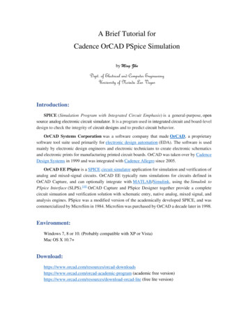
If you want to plot more complicated things, then you can write out an expression in the calculator inTools Calculator . In addition to arithmetic operations such as adding, subtracting, etc, some usefulexpressions are: VT , VS , VF are the voltage at a node for a transient simulation; a DC simulation; and an ACsimulation, respectively. Note that your expression must use the right expression for the type ofsimulation you are running. For example, to plot the voltage at node net4 in a DC simulation, youcould enter VS(”/net4”) IT , IS , IF are the current through a component terminal for a transient simulation; a DC simulation; and an AC simulation, respectively. Again, your expression must use the right expression for thetype of simulation you are running. For example, to plot the current through the drain of transistorM0 in a DC simulation, you could enter IS(”/M0/D”) dB20 converts a value to dB. Useful for AC transfer functions.You can use the save and open icons in the ADE L window to save and load the state of your simulationsetup so you don’t have to set it up all over again each time.4.4Parametric SweepsSometimes, the variable you want to sweep is a bit more complicated than a single parameter of a singlecomponent - maybe you want to sweep the widths of two transistors together, for example. In this case, youcan just type the name of your parameter in place of an actual value in the instance’s properties. Here is anexample with an NMOS transistor:It is good to give your parameters some descriptive name. Note that you don’t have to prefix theparameter names with p ; I just like to do that to clarify that I’ve made a parameter.Then in the ADE L window, right click in the Design Variables area and select Copy From Cellview.You should then see your variables appear. Make sure to give the variables some default value.17
4.4.1Secondary SweepsSometimes, you want to sweep more than one variable at once. For this, you can go to Tools ParametricAnalysis and add another sweep variable there. Be cautious of choosing too many points for the secondarysweep, as the plot could become very cluttered and the simulation could take a long time. If you are doinga secondary sweep this way, make sure to click the green play button in the Parametric Analysis windowrather than the one in the ADE L window.18
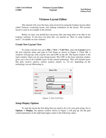
5Example Project: AmplifierIn this example project, we will create and simulate the DC transfer function of a common source amplifierwith source degeneration.NOTE: This is NOT the circuit you need to make for HW 1. HW1 asks you to simulate the IVcurves of the transistors. This is just an example to show you how to use Cadence Virtuoso.1. If Cadence is not launched, launch Cadence as shown in Section 3.2. In the Library Manager, create a new cell view. Give your cell view a useful name like cs amplifier .3. You should now see the schematic editor window. Create the following circuit using the Add Instancewindow and by placing wires. Check and save you schematic when you are done. Note that: The NMOS has a length of 0.5µm and a width of 10µm. Type these as 0.5u and 10u , respectively. Make sure to set the model name to NMOS Resistors can be found in the library analogLib as the cell res , where the resistance should be1k for Rs and 2k for Rd . The input source is a vdc source that has a DC voltage of 1.5 and an AC magnitude of 1 .The AC transfer function is not plotted in this guide, but feel free to try it for yourself. VDD 3V If you are unable to place an item, make sure that the library is analogLib and that the view issymbol in the add instance window.19
4. We will do an DC analysis for this example. Open the analog environment window and click onAnalyses, then Choose. In the window that appears: Select dc as the analysis Select Component Parameter as the sweep variable Type a forward slash and the name of you input source ( /Vin in this example) as the componentname Enter dc as the parameter name Select Start-Stop as the sweep range, and type 0 for the start and 3 for the stop so that therange is from 0V to VDD . Select Linear as the sweep type and enter a small value, like 0.001 , as the step size.Then click OK.20
5. In the analog environment window, click on Outputs, then To Be Plotted, then Select on Schematicto select your output. You will then need to click on the wire of output node on the schematic.6. In the analog environment window, click on Simulation, then Netlist and Run to run your simulation. Click OK on the Welcome to Spectre if it comes up. You can close the log window thatappears once the simulation is finished.21
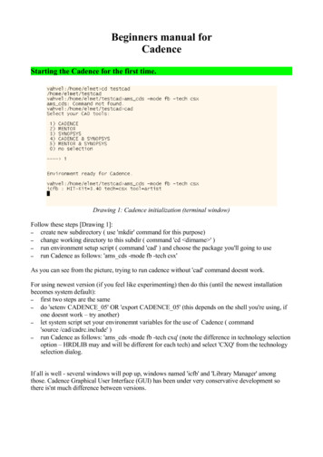
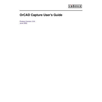
7. Your final result graph of the DC voltage transfer function should automatically pop up and shouldlook like the following picture.Note: If you want to plot the current into the terminal of a device (for e.g., into the drain of an NMOS),you can click on that terminal when selecting the output to plotNote: If you unintentionally select the wrong output to plot, you can select it in the analog environmentwindow and delete it using the red X symbol on the right22
2 One-Time Cadence Virtuoso Setup Note: This section only needs to be done once, not every time you want to use Cadence Virtuoso. You will need to do this even if you have Cadence set up for another class, since you will be using a particular model file for the simulations in this class. 1.Connect to your NoMachine desktop.