Transcription
A Brief Tutorial forCadence OrCAD PSpice Simulationby Ming ZhuDept. of Electrical and Computer EngineeringUniversity of Nevada Las VegasIntroduction:SPICE (Simulation Program with Integrated Circuit Emphasis) is a general-purpose, opensource analog electronic circuit simulator. It is a program used in integrated circuit and board-leveldesign to check the integrity of circuit designs and to predict circuit behavior.OrCAD Systems Corporation was a software company that made OrCAD, a proprietarysoftware tool suite used primarily for electronic design automation (EDA). The software is usedmainly by electronic design engineers and electronic technicians to create electronic schematicsand electronic prints for manufacturing printed circuit boards. OrCAD was taken over by CadenceDesign Systems in 1999 and was integrated with Cadence Allegro since 2005.OrCAD EE PSpice is a SPICE circuit simulator application for simulation and verification ofanalog and mixed-signal circuits. OrCAD EE typically runs simulations for circuits defined inOrCAD Capture, and can optionally integrate with MATLAB/Simulink, using the Simulink toPSpice Interface (SLPS).[18] OrCAD Capture and PSpice Designer together provide a completecircuit simuation and verification solution with schematic entry, native analog, mixed signal, andanalysis engines. PSpice was a modified version of the academically developed SPICE, and wascommercialized by MicroSim in 1984. MicroSim was purchased by OrCAD a decade later in 1998.Environment:Windows 7, 8 or 10. (Probably compatible with XP or Vista)Mac OS X 10.7 nloadshttps://www.orcad.com/orcad-academic-program (academic free rcad-lite (free lite version)
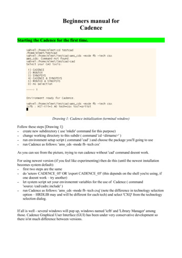
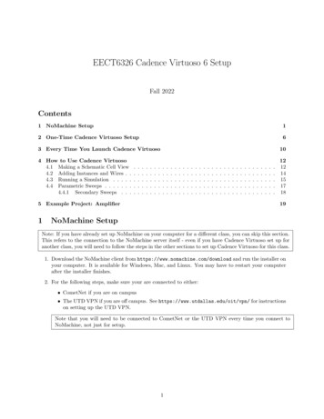
Simulation Step-by-Step1. Start OrCAD Capture CIS2. Start a new project using PSpice Analog or Mixed A/D.Create the project name and edit the project location if necessary.
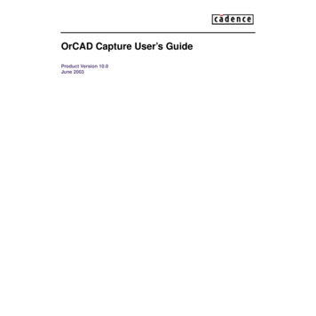
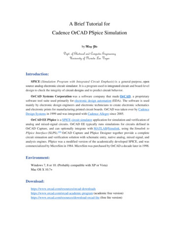
Click OK, and OK again in the following window.3. Now you can see the following window, and most icons in tool bar are in color now. You can see the files and their hierarchy at left side (Arrow #1). Use instance in right column (Arrow #2) to edit your schematic (Arrow #3). Document info are listed in right bottom corner (Arrow #4). Use probes and advanced analysis to observe circuit performance (Arrow #5)
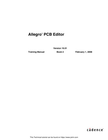
4. Add instances to build your circuit. A simple RC circuit is demonstrate below. Add and select new libraries and search for parts if necessary. Press “Enter” to select parts and drop it onto the schematic. Replace “GND” to the following symbol. Use “VAC” and “VSIN” as voltage source, respectively. Edit “VOFF”, “VAMPL”,“FREQ” in “Edit Properties.” and hit “Apply”. Compare the simulation results.
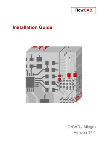
5. Wire the circuit and save the design/schematic file. Run the simulation (Arrow #1). Biased voltage values on connection nodes may be displayed (Arrow #2). A PSpice netlist will be created (Arrow #3) if there are no connection errors in theschematic. A “PSpice A/D (Lite)” window will pop up, to set up the simulation profile.
6. Create a new simulation profile, and inherit from an existing profile.7. Click “OK” and hit the “Run” button in OrCAD Capture CIS for simulation again. Rightclick in the black panel area and pull up the signal trace you want to observe. Place probeson schematics if necessary.
References:https://en.wikipedia.org/wiki/OrCADYou can ALWAYS learn from Internet (e.g. Google, Wikipedia, Youtube, etc.)!!
A Brief Tutorial for Cadence OrCAD PSpice Simulation . OrCAD was taken over by Cadence Design Systems in 1999 and was integrated with Cadence Allegro since 2005. OrCAD EE PSpice is a SPICE circuit simulator application for simulation and verification of analog and mixed-signal circuits. OrCAD EE typically runs simulations for circuits defined in OrCAD Capture, and can optionally integrate .