Transcription
Allegro PCB Editor Version 16.01Training ManualBook 2February 1, 2008This Technical tutorial can be found on https://www.jotrin.com
1990-2008 Cadence Design Systems, Inc. All rights reserved.Printed in the United States of America.Cadence Design Systems, Inc., 555 River Oaks Parkway, San Jose, CA 95134, USACadence TrademarksTrademarks and service marks of Cadence Design Systems, Inc. (Cadence) contained in this document are attributed to Cadence with the appropriate symbol.For queries regarding Cadence’s trademarks, contact the corporate legal department at the address above or call 800.862.4522.Allegro Accelerating Mixed Signal Design Assura BuildGates Cadence (brand and logo)CeltIC Conformal Connections Diva Dracula ElectronStorm Encounter EU CAD Fire & Ice First Encounter HDL-ICE Incisive InstallScape IP Gallery NanoRoute NC-Verilog NeoCell NeoCircuit OpenBook online documentation libraryOrCAD Palladium Pearl PowerSuite PSpice SignalStorm Silicon Design Chain Silicon Ensemble Silicon Express SKILL SoC Encounter SourceLink online customer supportSpecman Spectre Speed Bridge UltraSim Verifault-XL Verification Advisor Verilog Virtuoso VoltageStorm Xtreme Other TrademarksOpen SystemC, Open SystemC Initiative, OSCI, SystemC, and SystemC Initiative are trademarks or registered trademarks of Open SystemC Initiative, Inc. inthe United States and other countries and are used with permission.All other trademarks are the property of their respective holders.Confidentiality NoticeNo part of this publication may be reproduced in whole or in part by any means (including photocopying or storage in an information storage/retrieval system)or transmitted in any form or by any means without prior written permission from Cadence Design Systems, Inc. (Cadence).Information in this document is subject to change without notice and does not represent a commitment on the part of Cadence. The information contained hereinis the proprietary and confidential information of Cadence or its licensors, and is supplied subject to, and may be used only by Cadence’s customer in accordancewith, a written agreement between Cadence and its customer. Except as may be explicitly set forth in such agreement, Cadence does not make, and expresslydisclaims, any representations or warranties as to the completeness, accuracy or usefulness of the information contained in this document. Cadence does notwarrant that use of such information will not infringe any third party rights, nor does Cadence assume any liability for damages or costs of any kind that mayresult from use of such information.RESTRICTED RIGHTS LEGEND Use, duplication, or disclosure by the Government is subject to restrictions as set forth in subparagraph (c)(1)(ii) of theRights in Technical Data and Computer Software clause at DFARS 252.227-7013.UNPUBLISHED This document contains unpublished confidential information and is not to be disclosed or used except as authorized by written contract withCadence. Rights reserved under the copyright laws of the United States.
Table of ContentsAllegro PCB EditorNOTE: Lab exercises for this class were developed in cooperation with Altera Corporation to provide real designexamples. Please read the following notice before proceeding with the course.CUSTOMER TERMS AND CONDITIONS1. License Grant. Subject to the limitations contained herein, Cadence hereby grants to Customer a limited, revocable,non-transferable, non-sublicenseable, non-exclusive license to use, copy, have copied, modify, create or have createdderivative works, perform, and display the database design # 140-0365000-01 Rev C (“Design”) solely to aid inits/their training on the use of Cadence products (“Training”). Customers is expressly prohibited from (a) using theDesign to develop or program any non-Altera devices, and (b) distributing, selling, and/or otherwise marketingproducts containing the Design to any third party. Notwithstanding any provision of this agreement to the contrary,Altera shall at all times retain all title to and ownership of the Design and any derivative works created by Customer.All rights not expressly granted herein or to Cadence and/or its Customers shall be retained by Altera.2.Confidentiality. The Design is Altera confidential information. Customer agrees not to disclose the Designto any third party or use the Design for any purpose other than the purposes set forth in Section 1. Upon written demandby Altera or Cadence, Customer shall: (a) immediately cease using Altera’s confidential information, (b) return theconfidential information and all copies, notes or extracts thereof in its possession to Altera or Cadence within seven (7) daysof receipt of demand, (c) destroy all residual copies, notes or extracts of the confidential information, and (d) upon Altera’sor Cadence’s request, immediately certify in writing that Customer have complied with the obligations set forth in thisparagraph.3.No Warranties. The Design is provided to Customer on an AS-IS basis. CADENCE AND ALTERASPECIFICALLY DISCLAIMS ALL WARRANTIES, INCLUDING, WITHOUT LIMITATION, THEWARRANTIES OF NON-INFRINGEMENT, MERCHANTABILITY, FITNESS FOR A PARTICULAR PURPOSE,OR ANY WARRANTY THAT THE DESIGN WILL BE DEFECT-FREE OR BUG-FREE. Customer acknowledgesthat neither Cadence nor Altera has any obligation to provide any maintenance or support in connection with its/theiruse of the Design.4.Limitation of Liability. IN NO EVENT SHALL ALTERA OR CADENCE BE LIABLE UNDER ANYLEGAL THEORY, WHETHER IN TORT, CONTRACT OR OTHERWISE (a) FOR ANY LOST PROFITS, LOSTREVENUE OR LOST BUSINESS, (b) FOR ANY LOSS OF OR DAMAGES TO OTHER SOFTWARE OR DATA,OR (c) FOR ANY INCIDENTAL, DIRECT, INDIRECT, CONSEQUENTIAL OR SPECIAL DAMAGESRELATING TO THE USE OF THE DESIGN BY CADENCE OR ANY CUSTOMER, EVEN IF ALTERA HASBEEN ADVISED OF THE POSSIBILITY OF SUCH LIABILITY AND NOTWITHSTANDING ANY FAILURE OFESSENTIAL PURPOSE OF ANY LIMITED REMEDY STATED HEREIN. Some jurisdictions do not allow thelimitation or exclusion of special, incidental or consequential damages, so the above limitations or exclusions may notapply to Customer in full but shall be interpreted to apply to the maximum extent permissible under applicable law.5.Termination. Cadence may terminate this agreement (a) at any time for any reason by providing Customer atleast thirty (30) days prior written notice or (b) immediately upon breach of this agreement by Customer. The licenserestrictions and the ownership terms in Section 1, and Sections 2 through 7 shall survive the termination of thisagreement.6.Export. Customer shall not export or re-export, directly or indirectly, the Design without first obtaining anynecessary U.S. or other governmental licenses and approvals.7.General Provisions. Customer agrees that the validity and construction of these terms and conditions shall begoverned by the laws of the State of California, without regard to conflict of law or choice of law principles. Customeragrees to submit to the exclusive jurisdiction of the courts in the State of California for the resolution of any dispute orclaim arising out of or relating to these terms and conditions. Cadence and Customer hereby agree that the party whodoes not prevail with respect to any dispute, claim, or controversy relating to these terms and conditions shall pay thecosts actually incurred by the prevailing party, including any attorneys’ fees. Each party agrees to waive its rights to ajury trial related to these terms and conditions.February 1, 2008Cadence Design Systems, Inc.iii
Allegro PCB EditorivTable of ContentsCadence Design Systems, Inc.February 1, 2008
ContentsLesson 1: Customizing PCB Editor to Increase Productivity.1-1Course Directory Structure.1-2PCB Editor Database Tool - DBDoctor .1-3PCB Editor Initialization .1-6The PCB Editor Environment.1-8Global Environment File - 1.1-9Environment File Variables.1-13Labs .1-19Lab 1-1: Managing Your User Environment .1-20Lab 1-2: Customizing the PCB Editor User Interface .1-27Answers to Search Path Quiz .1-29Lesson 2: High-Speed Constraint Management .2-1The Constraint Manager .2-2The Constraint Manager Main Window.2-3Creating an Electrical Constraint Set.2-6Assigning the ECSet to Objects.2-8DRCs in Constraint Manager .2-11Labs .2-12Lab 2-1: Constraint Manager Tour .2-13Lab 2-2: Using the Constraint Manager .2-17Lesson 3: More Constraints .3-1Electrical DRC Modes.3-3On-Line DRC .3-4Design Constraints.3-5Constraint Regions .3-7Creating a Region-Class Rule.3-10Nets and Xnets.3-11Labs .3-12Lab 3-1: Viewing Existing Rules Previously Defined in a Board Design.3-13Lab 3-2: Routing Lines on Specified Subclasses.3-15Lab 3-3: Defining Extended Design Rules for Regions .3-21Lab 3-4: Automatically Routing the Extended Design Rules.3-23Lesson 4: Differential Pairs .4-1Defining Diff Pairs in Constraint Manager .4-6Defining Diff Pair ECSets .4-7Assigning the ECSets to the Diff Pair .4-9Turn DRC Checking On .4-10Primary Gap.4-11Primary Line Width .4-12Neck Gap and Neck Width.4-12Separation Gap Tolerance .4-13Minimum Line Space .4-14Max Uncoupled Length .4-15February 1, 2008Allegro PCB Editorv
Allegro PCB EditorTable of ContentsGather Control .4-16Phase Tolerance .4-17Interactively Routing Diff Pairs.4-18Differential Impedance Calculator .4-21Different Rules for Different Layers .4-22Lab .4-23Lab 4-1: Differential Pair Setup.4-24Lab 4-2: Defining Diff Pairs and Routing using the PCB Router .4-31Lesson 5: Interactive Etch Editing.5-1Reviewing Basic Techniques.5-2Group Routing .5-10Tips for Interactive Routing.5-11Lab .5-13Lab 5-1: Adding and Editing Etch .5-14Color Visibility Views.5-25Using the My Favorites Color Folder.5-26Displaying Disconnected Pins on VCC and GND .5-27Labs.5-29Lab 5-2: Changing Color Visibility for Routing.5-30Lab 5-3: Viewing Disconnected Voltage Pins.5-32Controlling Line Length .5-37Delay Tuning .5-38Etch Length Readout on Non-Critical Traces .5-39Display Parasitics on a Connect Line .5-40Z Axis Delay.5-42Pin Delay .5-43Lab .5-44Lab 5-4: Controlling Line Length.5-45High-Speed Etch Editing .5-53Logical Net Editing.5-57Lab .5-58Lab 5-5: Rat Ts .5-59Lesson 6: Copper Planes.6-1Split Planes .6-2Complex Planes .6-4Negative Plane Island Check .6-7Labs.6-8Lab 6-1: Split Plane Using Anti-Etch Subclass .6-9Lab 6-2: Split Plane Using Add Polygon.6-13Lab 6-3: Complex Planes.6-24Lab 6-4: Viewing Negative Shapes and Negative Plane Island Check .6-27Lesson 7: Testpoint Generation .7-1How Testprep Works.7-4Setting Testprep Properties.7-5Setting Testprep Parameters .7-7Padstack Selections.7-12Probe Types .7-13Generate Testpoints .7-14viCadence Design Systems, Inc.February 1, 2008
Table of ContentsAllegro PCB EditorThe Testprep Log File .7-15Lab .7-17Lab 7-1: Test Preparation .7-18Altering Testpoints .7-24Fixing Testpoints and Creating a Fixture .7-25Unit Area Check .7-27Unit Area Check Density Log .7-28Component Area Check.7-29Component Area Check Density Log.7-30Generating a Drill File for the Test Fixture.7-31Lab .7-32Lab 7-2: Interactively Working with Testpoints.7-33Lesson 8: Technology Files .8-1Reasons for Using Technology Files.8-2Lab .8-6Lab 8-1: Using Technology Files .8-7Lesson 9:Glossing.9-1Preparing for Automatic Glossing.9-1The Glossing Controller .9-3Labs .9-14Lab 9-1: Fixing Critical Nets before Glossing.9-15Lab 9-2: Using Gloss for Sequential Cleanup .9-17Labs .9-21Lab 9-3: Adding and Removing Fillets .9-22Lab 9-4: Custom Smoothing.9-24Lesson 10: Design For Assembly .10-1DFA Overview .10-1DFA Feedback.10-2DFA Procedures .10-3Library Adoption Process.10-4DFA Symbol Update Utility.10-5DFA Update Log File .10-6DFA Boundary Area.10-7DFA Constraint Dialog Spreadsheet .10-8Adding Footprints to the Spreadsheet .10-9Adding Symbol Classifications .10-10Initial Load of Library Symbols with Classes .10-11Purging Classified Symbols.10-12Setting DFA Spacing Values.10-13Saving the Spreadsheet.10-14Loading a DFA Spreadsheet.10-15A Loaded DFA Spreadsheet .10-16DFA Driven Interactive Placement .10-17Lab .10-17Lab 10-1:Placing Parts with DFA Rules .10-18Lab 10-2:Updating Parts for DFA .10-20Lesson 11: Automatic Placement Tools .11-1Prerequisites for Placement .11-2February 1, 2008Cadence Design Systems, Inc.vii
Allegro PCB EditorTable of ContentsAccessing PCB Router Autoplacement .11-3Interactive Placement Hints.11-6Lab .11-7Lab 11-1:Automatic Placement using PCB Router .11-8Lesson 12: Accessing Information to Enhance Productivity with PCB Editor .12-1cdnshelp - Cadence Online Documentation .12-2What is SourceLink?.12-4Available Web Resources.12-9Live and Archived Webinars .12-10Labs.12-11Lab 12-1:Starting the Online Documentation.12-12Lab 12-2:Opening Documents.12-13Lab 12-3:Using the Command Bar.12-15Lab 12-4:Searching Documents.12-16viiiCadence Design Systems, Inc.February 1, 2008
1Lesson 1: Customizing PCB Editor to IncreaseProductivityLearning ObjectivesIn this lesson you will: Review the course directory structure and get information about how thePCB Editor database works using DB Doctor or Write Locks. Identify which files are generated when starting PCB Editor. Personalize the PCB Editor environment: Variables Function keys Aliases Define the differences between macros and scripts.In this lesson you will learn to customize the Allegro PCB Editor environment toaccelerate design work by using macros, scripts, aliases and function key definitions, andsetting User Preferences options.This part of the course does not follow a design flow. The objective is to broaden yourknowledge by introducing ways that can help you to become a productive user of the tool.We worked with the Allegro PCB Design L tool earlier in the course. This part of thecourse uses Allegro PCB Design XL. During the rest of the course there is no specificdesign flow. The course material continues assuming you know the basics of the tool. Weplan to show you the power of the PCB Editor tool, which hopefully will encourage you towork further with the tool on your own.February 1, 2008Allegro PCB Editor1-1
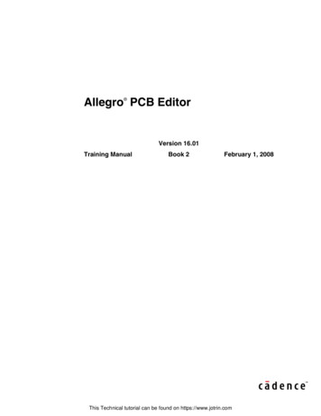
Customizing PCB Editor to Increase ProductivityLesson 1Course Directory Structure root dir Directory structure forthis course installation course inst dir
Trademarks and service marks of Cadence Design Systems, Inc. (Cadence) contained in this document are attributed to Cadence wit h the appropriate symbol. For queries regarding Cadence's trademarks, contact the corporate legal department at the address above or call 800.862.4522. Confidentiality Notice