Transcription
Significant Features of High-Strength SteelWeld Metal MicrostructuresOptimal combinations of microstructure and mechanicalproperties are identified for high-strength steel submergedarc weld metalBY P. T. OLDLAND, C. W. RAMSAY, D. K. MATLOCK AND D. L. OLSONABSTRACT. Microstructural changes withheat input during submerged arc weldingof a high-strength, low-carbon, 5 wt-%nickel Cr-Mo steel were evaluated withboth optical and transmission electronmicroscopy (TEM), and the results werecorrelated with mechanical properties. Aclassification scheme was developed toidentify the complex microstructural features observed in the TEM analysis ofhigh-strength steel weld metal. Anincrease in heat input from 1 to 4 MJ/m(25 to 100 kj/in.), decreased the strength,increased the ductility and the toughness,and caused the weld metal microstructure to change from autotempered martensite to a mixture of martensite, bainite,and retained austenite. An optimal combination of microstructure and propertieswas identified, and the potential for modifying the consumable compositions toproduce this structure over a wide rangeof heat inputs was discussed, based oncontinuous cooling transformation behavior.IntroductionThe economical utilization of highstrength steels with yield strengths greater than 690 MPa (100 ksi) in fabricatedstructures depends on the use of highheat-input welding processes, properselection of welding consumables, andpreheat and postweld heat treatmentprocedures. Significant literature on thewelding of high-strength steel exists, butmuch of this work is focused on theheat-affected zone microstructure andproperties (Refs. 1-6). There is only limited literature on the microstructure andproperties of high-strength-steel weldmetal (Refs. 7-10).P. T. OLDLAND, C. W. RAMSAY, D. K. MATLOCK and D. L. OLSON are with the Centerfor Welding Research, Colorado School ofMines, Golden, Colo.Paper presented at the 69th Annual AWSMeeting, held April 17-22, 1988, in NewOrleans, La.158-s APRIL 1989The submerged arc welding processhas been successfully applied (Ref. 11) tolower-strength "ferritic" steels with yieldstrengths less than 690 MPa in the 1 to 4MJ/m (25 to 100 kj/in.) heat input range.In contrast, submerged arc welding ofhigh-strength steels with heat inputsgreater than 2 MJ/m (50 kj/in.) does notyet consistently produce weldments withacceptable combinations of strength andtoughness (Ref. 11). To extend the usableheat input ranges for submerged arcwelding of high-strength steels, a quantitative characterization of the microstructure and mechanical properties isrequired. A fundamental understandingof the influence of heat input on themicrostructure and properties of highstrength-steel weld metal will lead toincreased utilization of these materials.ing arc. The final microstructures in steelweld deposits result from austeniticdecomposition, either through the nucleation and growth of ferrite and bainite orthrough the athermal transformation tomartensite, which can be modified by avariety of precipitation reactions (Ref.12). Previous studies have shown thatweld metals with yield strengths less than560 MPa (80 ksi) consist primarily offerrite, while weld metals with yieldstrengths greater than 690 MPa (100 ksi)consist primarily of martensite and bainite(Refs. 13-15). In this paper, a detailedanalysis of effects of heat input on microstructural development in high-strengthsteel weld metal is presented.Variations in high-strength-steel weldmetal microstructures and properties areprimarily due to two factors: the coolingrate and the weld metal composition.The cooling rate experienced by theweld metal deposit is controlled by acombination of heat input and heatextraction. The heat extraction from theweld pool depends on joint geometry,plate thickness, and extent of preheat.The rate of heat extraction increases withan increase in plate thickness or adecrease in the preheat temperature.The weld metal composition is dependent on base metal and electrode wirecompositions, dilution, and the pyrometallurgical chemical reactions in the weld-A low-carbon, 5 wt-% nickel Cr-Mohigh-strength steel was received in theform of 51-mm (2-in.) thick plate, andwelds were prepared with t w o weldingwires, identified as wire 1 and wire 2, andone commercial basic welding flux. Complete chemical analyses of the base metaland welding wires are presented in Table1. The nominal composition of the fluxused in this study is listed in Table 2.Single-pass, bead-on-plate weldmentswere prepared by the submerged arcwelding process over a heat input rangeof 1.2 to 3.7 MJ/m (30 to 93 kj/in.) forfive test series. Series I and ll weldmentswere produced on 300- X 51- X 19-mm(12- X 2- X 0.75-in.) coupons using electrode wires 1 and 2. These initial weldments were used in a screening processto determine the compositional stability,hardness, and microstructural changesoccurring with changes in heat input.Series III weldments, which were used forthe majority of this study, were producedon 690- X 76- X 51-mm (27- X 3- X 2in.) coupons with a 6.5-mm-deep (0.25in.) 60-deg included angle groove, usingelectrode wire 1. The larger couponswere used to provide a significant heatsink. However, the cooling rate in thelaboratory coupons may be less thanwould be obtained in full-size structures.KEY W O R D SHigh-Strength SteelHY-130 Steel WeldsWeld MicrostructuresSubmerged Arc WeldingEmission SpectrometerARL SpectrometerOptical MetallographyMartensite BainiteFractographyExperimental Procedure
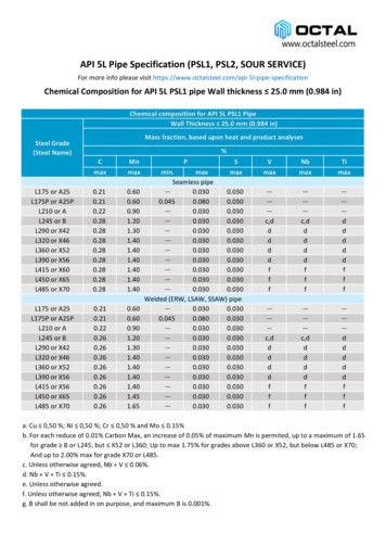
Table 1—Chemical Compositions of the 5 wt-% Nickel Cr-Mo High-Strength-Steel Base Metal, Welding Wires and FluxMaterialCMnSiPSNiMoCrCuBase plateWire 1Wire able 2—Nominal Chemical Composition of Submerged Arc Welding Flux in wt-%FluxSi0 2AI2O3MgOMnOCaOTi02CaF2Na20Fe 2 0 3C10.717.231.76.61.10.8624.10.781.90:35T h e w e l d g r o o v e w a s necessary t o p r o vide e n o u g h w e l d b e a d f o r mechanicaltesting and t o yield a p p r o x i m a t e l y t h esame dilutions o b t a i n e d in Series I and IIw e l d m e n t s . A d d i t i o n a l w e l d metal p r o d u c e d in Series III w a s used f o r Series IVa n d V in an a t t e m p t t o simulate theeffects of reheating o f w e l d metal d u r i n gmultipass w e l d i n g . This w a s a c c o m plished b y heat treating t w o sets o fC h a r p y V - n o t c h samples f o r 1 m i n at6 8 8 a n d 8 3 2 C ( 1 2 7 0 a n d 1529 F), f o rSeries IV and V , respectively, f o l l o w e d b yair c o o l i n g . D i a m o n d p y r a m i d hardnessmeasurements w e r e m a d e o n t h e t e m p e r e d w e l d metal a n d t h e Series III w e l dmetal for c o m p a r i s o n . These t e m p e r e dspecimens w e r e b r o k e n at t e m p e r a t u r e snear the ductile-to-brittle transition t e m peratures of t h e u n t e m p e r e d w e l d s .Chemical analyses of t h e as-receivedbase plate a n d the w e l d metal of Series I,II, III, IV a n d V w e r e o b t a i n e d using an ARLemission s p e c t r o m e t e r (for the elementsmanganese, silicon, p h o s p h o r u s , nickel,m o l y b d e n u m , c h r o m i u m , c o p p e r , vanad i u m a n d titanium) a n d w i t h a Leco interstitial c o m b u s t i o n analyzer (for c a r b o na n d sulfur).W e l d m e n t s p r o d u c e d in Series I, II andIII w e r e e v a l u a t e d w i t h standard opticalmetallographic m e t h o d s t o characterizeb o t h t h e m a c r o s t r u c t u r e a n d microstruct u r e o f each w e l d . T h e w e l d metal specimens w e r e s e c t i o n e d transverse t o thewelding direction, m o u n t e d , and mechanically polished t h r o u g h 0.05pmAI2O3 p o w d e r . Several special etchantsw e r e used in this study, a n d it w a sd e t e r m i n e d that LePera's e t c h (Ref. 16)r e v e a l e d details o f t h e solidification struct u r e that w e r e n o t o b s e r v a b l e w i t h stand a r d Nital steel etchants. T h e LePera'sand Nital etchants, the e t c h i n g p r o c e d u r e , and their effect o n t h e microstruct u r e are p r e s e n t e d in Table 3. T h e samples w e r e e t c h e d w i t h LePera's e t c h ,analyzed, r e p o l i s h e d , e t c h e d w i t h Nital,a n d analyzed again. Longitudinal sectionsw e r e p r e p a r e d in t h e Series III w e l d m e n t snear t h e centerline t o o b t a i n , along w i t ht h e transverse m i c r o g r a p h s , a t h r e e dimensional v i e w o f the w e l d metalmicrostructures. Series III specimens usedf o r optical m i c r o s c o p y w e r e analyzedusing a scanning e l e c t r o n m i c r o s c o p ew i t h e n e r g y dispersive x-ray s p e c t r o m e try. Series III w e l d metal specimens, w h i c hw e r e analyzed w i t h the transmission electron microscope, w e r e punched f r o mw a f e r s of w e l d metal cut transverse t ot h e w e l d i n g d i r e c t i o n . These w a f e r s w e r epolished w i t h a t w i n - j e t electropolisher in5 v o l - % p e r c h l o r i c acid, and 95 v o l - %acetic acid solution at 1 3 C (55 F).Hardness measurements w e r e m a d eo n the transverse sections of Series I, IIand III w e l d s using the R o c k w e l l hardnesstester. M e c h a n i c a l testing of t h e Series IIIw e l d s consisted o f tensile testing of flatall-weld-metal tensile bars in a c c o r d a n c ew i t h A S T M standards (Ref. 17), w i t h ar e d u c e d gage section o f 25 X 6.3 X 3.7m m ( 1 X 0 . 2 5 X 0 . 1 4 in.), a n d C h a r p yV - n o t c h toughness testing. A S T M stand a r d 5-mm-thick (0.2-in.) subsized Charp y specimens (Ref. 18) w e r e m a c h i n e df r o m Series III, IV and V w e l d s . T h enotches w e r e o r i e n t e d t o cause crackp r o p a g a t i o n along t h e w e l d centerline inthe welding direction.Fracture surfaces of Series III C h a r p yV - n o t c h samples b r o k e n at — 1 9 6 C(—321 F) w e r e analyzed using e n e r g ydispersive x-ray s p e c t r o m e t r y o n t h escanning e l e c t r o n m i c r o s c o p e . T h e features o f t h e fracture surfaces w e r e t h e nc o m p a r e d t o t h e w e l d metal microstructures. A qualitative analysis of s o m e inclusions present o n the f r a c t u r e surfacesw a s c o n d u c t e d d u r i n g this study.ResultsCompositional StabilityThe w e l d metal chemical c o m p o s i t i o n sa n d delta quantities f o r Series I, II and IIIare listed in Table 4. T h e data in Table 4include t h e series n u m b e r , heat input,a n d dilution f o r each w e l d s p e c i m e n ascalculated directly f r o m measurements ofb e a d g e o m e t r y . H e r e , t h e dilution w a sheld t o a range of 45 t o 5 5 % .The c o m p o s i t i o n a l stability of the w e l ddeposit w a s e v a l u a t e d using t h e deltaquantity (Ref. 19). T h e delta q u a n t i t y ist h e d i f f e r e n c e b e t w e e n t h e analytical(measured) w e l d metal c o m p o s i t i o n a n dt h e p r e d i c t e d (calculated) w e l d metalc o m p o s i t i o n , based o n dilution of t h ee l e c t r o d e w i r e a n d t h e m e l t e d base m e t al. T h e delta quantity directly reflects thechemicalreactionsoccurringduringw e l d i n g . A positive delta q u a n t i t y f o r anelement indicates that the element w a sa d d e d t o t h e w e l d p o o l f r o m t h e flux. ATable 3—Summary of Special Etchants, Etching Procedure and the Etching Effect on the WeldMetal MicrostructureEtchantProcedureEffect on MicrostructureNital2% nitric in methanol. Swab at roomtemperature for approximately 45seconds.Etches grain boundaries. Highlightssecond phase, such as martensite,and bainite.LePera's1% sodium metabisulfate in distilledwater plus 4% picric acid in ethanol,mixed in a 1:1 volume ratio. Thespecimen should be etch-polishedusing 4% picral to remove all thedisturbed metal (approximatelythree etch-polished sequences aresufficient). The etchant is thenmixed and the specimen isimmediately immersed for 5-10seconds.Martensite appears white, bainiteappears black, ferrite appears tan(or gray). Shows coring ofsolidification structure in weldmetal.W E L D I N G RESEARCH S U P P L E M E N T 1159-s
Table 4 - -Chemical Compositions, Delta Quantities, Heat Inpul s and Dilutions for Series I, II and III, Sing e-Pass Weld Metal, in .0090.0100.0090.0090.009Delta Quantitiesnegative delta quantity for an elementindicates that the element was extractedfrom the weld pool due to chemicalreactions with the liquid flux. The elements that exhibited significant deltaquantities were carbon, manganese andsilicon. The delta quantities for thesethree elements were shown to be independent of heat input in the 1 to 4 MJ/mrange. Silicon and manganese had positive delta quantities of 0.10 wt-% and0.05 wt-%, respectively. However, thecompositional changes to the weld poolrepresented by these delta quantities donot have a significant effect on the hardenability of the weld metal (Ref. 20).Carbon had a negative delta quantity,resulting in a decrease in the weld metalcarbon content of approximately 0.01wt-% to a mean value of 0.081 wt-%. Asshown in Table 4, the delta quantities forthe remaining alloying elements werenegligible.In general, the weld metal compositionwas stable with a change in heat input.This stability results primarily from the useof a highly basic flux with a low silicacontent. Silica is a major oxygen source insubmerged arc welding, and thus the lowsilica content minimizes the oxidationpotential of the weld pool (Ref. 21). Thedelta quantities remained constant withvariations in heat input. This observationsuggests that variations in wire composition can be conveniently used to make160-sl APRIL 1989Nisystematic alterations of the weld metalcomposition and, thus, weld microstructure and properties. This also suggeststhat variations in cooling rate withchanges in heat input are responsible forthe observed microstructural changesdiscussed below.Mechanical PropertiesThe mechanical properties of theweldments varied systematically withheat input. The hardnesses of the weldmetal produced in Series I and II on300- X 51- X 19-mm coupons, and SeriesIII on 690- X 76- X 51-mm coupons areshown in Fig. 1. For all three series, thehardness decreased with an increase inheat input. The hardness of Series I weldmetal produced with wire 1 decreasedfrom Rockwell C 38 at 1.2 MJ/m (31kj/in.) to Rockwell C 31 at 3.7 MJ/m (94kj/in.). The hardness of the Series ll weldmetal produced with wire 2 was consistently lower than that of Series I weldmetal, and varied from Rockwell C 37 at1.2 MJ/m to Rockwell C 29 at 3.7 MJ/m.The thicker plate and the more complexgeometry used for Series III resulted inhigher cooling rates at a given heat input.Therefore, the Series III weld metal hardnesses produced with wire 1 were consistently higher than the correspondingdata for Series I and II weld metal, andvaried from Rockwell C 39 at 1.2 MJ/mto Rockwell C 35 at 3.7 MJ/m.Figure 2 shows the room-temperaturetensile properties of Series ill weld metalas a function of heat input. Both the yieldand ultimate tensile strengths decreasedand the elongation to failure increasedwith an increase in heat input. As shownin Fig. 2, an increase in the heat input by afactor of three results in a decrease in theyield strength from 950 MPa (140 ksi) to850 MPa (120 ksi), a decrease in ultimatetensile strength from 1240 MPa (180 ksi)to 1080 MPa (160 ksi), and an increase inthe tensile ductility from 10 to 15%. Thedata in Fig. 2 correspond directly to thehardness data in Fig. 1.Energy absorbed and percent brittlefracture versus test temperature transition curves were obtained for ASTMstandard 5-mm subsized Charpy V-notchspecimens from Series III, IV and V weldmetal. The transition curves obtained byplotting all available data for 1.2-, 2.5- and3.7-MJ/m (30-, 64- and 94-kJ/in.) heatinputs are shown in Figs. 3A, B and C,respectively. There is limited scatter in thedata in Figs. 3A, B and C. All weldsexhibited a transition from ductile to brittle fracture behavior over the test temperature range investigated. The Series III1.2-MJ/m weld shows a narrow ductileto-brittle transition behavior (see Fig. 3A),while the transitions from the upper shelfto the lower shelf for the 2.5-MJ/m and3.7-MJ/m welds are gradual and occur
45— i1111rHIGH STRENGTH STEELWELD METAL1400HIGH STRENGTH STEELWELD METALSERIES I I I401200UJxu§ 351000UjCOLU80020.060015.0orx 30oD SERIES ISERIES IISERIES IIIl251.01.510.0400WIRE 1WIRE 2WIRE 1 Al3.52.02.53.0HEAT INPUT (MJ/m)4.0HOO1.0ULTIMATE TENSILE STRENGTH0.2% YIELD STRENGTHTOTAL ELONGATION2.0HEAT INPUT3.0(MJ/m)cnLUa. 5.00Fig. 1 — Rockwell C hardness as a function of heat input for Series I and II Fig. 2 —Ultimate tensile strength, 0.2% offset yield strength, and totalsingle-pass welds produced on 300- X 51- X 19-mm coupons, and for elongation to failure as a function of heat input for Series III single-passSeries III single-pass welds produced on 690- X 76- X 51-mm coupons weld metalover a range of approximately 100 C(180 F), as shown in Figs. 3B and C,respectively.To interpret the data shown in Fig. 3, aductile-to-brittle transistion temperature(DBTT) is defined at 15 J (11 ft-lb)absorbed energy. The fracture appearance transition temperature (FATT) isdefined to be at 50% brittle fracture. The15-J DBTT for Series III weld metaldecreases with increasing heat input from- 7 0 C (-94 F) at 1.2 MJ/m to - 1 3 3 C(—207 F) at 2.5 MJ/m and increasesslightly to - 1 1 3 C ( - 1 7 1 F) at 3.7 MJ/m.Similarly, the 50% FATT decreased withincreasing heat input from —90 C(-130 F) at 1.2 MJ/m to - 1 2 0 C(-184 F) at 2.5 MJ/m and increasedslightly to - 1 0 4 C (-155 F) at 3.7 MJ/m.These trends are shown in Figs. 3A, B andC. The upper-shelf absorbed energy forSeries III weld metal, shown in Figs. 3A, Band C, increased from 22 J (16 ft-lb) at 1.2MJ/m to 32 J (24 ft-lb) at 2.5 MJ/m, andto 34 J (25 ft-lb) at 3.7 MJ/m. The lowershelf of absorbed energy of Series III weldmetal remained fairly constant with heatinput, 2 J (1.5 ft-lb) at 1.2 MJ/m and 3.7MJ/m, and 3 J (2 ft-lb) at 2.5 MJ/m.input are shown in Fig. 4. Reheating theweld metal decreases the hardness in allcases. The hardness of Series IV weldmetal, heated to 688 C (1270 F),decreases with increasing heat input. Thissoftening corresponds to an aging treatment for steel when heated in the subcritical temperature range, below theAc-i. The Series V weld metal hardnessincreases with increasing heat input. Thisis due to a secondary strengtheningeffect occurring in the weld metal, possibly from recrystallization when heated to832 C (1530 F), in the intercritical temperature range, between the Ac- and theAC3. Also, austenite formed during inter-Series IV and V specimens were testedto determine the effects of reheating onthe weld metal mechanical properties.The diamond pyramid hardnesses forSeries 111, IV and V as a function of heatvcritical annealing may transform on cooling to martensite or bainite, producingstrengthening.The effects of reheating on the ductileto-brittle transition behavior of the weldmetal as described by either DBTT or theFATT were also analyzed. The partialtransition curves for the reheated weldmetal for 1.2-, 2.5- and 3.7-MJ/m heatinputs are shown in Figs. 3A, B, and C,respectively. The DBTT and FATT inSeries IV and V are summarized in Table 5for the 1.2-, 2.5- and 3.7-MJ/m weldmetal. The DBTT and FATT are also listedin Table 5 for the Series III, nonreheatedweld metal, for reference. Most of theTable 5—Summary of Ductile-to-Brittle Transition Temperatures (DBTT) and FractureAppearance Transition Temperatures (FATT) a SeriesIVHeat Input (MJ/m)2.5Property1.2DBTT ( 5(-104)-78-120(-133)-104(-113)FATT ( C)DBTT ( C)(-70)FATT ( C)3.7-68-95-80(-90)(-120)(-104)(a) Reheated specimens, Series IV and V, single-pass weld metal produced at 1.2, 2.5 and 3.7 MJ/m, and as-welded Series III weldmetal at corresponding heat inputs, in parentheses for reference.WELDING RESEARCH SUPPLEMENT 1161-s
specimens showed an increase in theDBTT and FATT when reheated. The1.2-MJ/m weld metal was affected mostwhen reheated to 688 C, Series IV,which caused the DBTT to increase 20 C(36 F) and the FATT to increase 50 C.(90CF). Two combinations of reheatingtemperature and heat input caused adecrease in the DBTT. The 1.2-MJ/mweld metal DBTT decreased 8 C (14 F)when reheated to 832 C, Series V, whilethe FATT increased 22 C (39 F) in thesame specimens. This situation alsooccurred in the 3.7-MJ/m weld metalwhen reheated to 688 C, Series IV. Theweld metal DBTT decreased 15 C (27 F),while the FATT increased 9 C (16 F)when reheated.4035MBZll i.30JJR25mDi 3--.E'J*r *XInxicr - cn 2 0CB5 15UJz E710- ».5-100-50TEMPERATURE0( C)4035HIGH STRENGTH STEELWELD METALHEAT INPUT 2 . 5 MJ/m30SERIESNUMBERIIIIVVcn 20HEATTREATMENTNONEO B8B C a A AB32 C15ENERGYOOABSORBED10PERCENT BRITTLEFRACTURE Acr100UJDC75A50crLUCD2500 I-250-200-150-100-50TEMPERATURE403511050100150B( C)1—HIGH STRENGTH STEELWELD METALHEAT INPUT 3 . 7 MJ/m30SERIESNUMBER 25HEATTREATMENTNONE688 C832 CIIIIVVcn 20CD 15cr10cr100 3O " A A75ENERGYOD AABSORBED50PERCENT BRITTLEFRACTURE A25UJCL-250-200-150-10050-50TEMPERATURE100150 C)Fig. 3-Energy absorbed and percent brittle fracture versus test temperature transition curves forSeries III single-pass weld metal produced at various heat inputs. A - 1.2 MJ/m; B — 2.5 MJ/m;C-3.7MJ/m162-s APRIL 1989The fracture surfaces of the Series IIICharpy specimens broken in the uppershelf region of the transition curvesshowed fully ductile fracture. Decreasingthe test temperature through the transition zone caused the fracture to bemixed between ductile and brittle modesuntil the lower shelf was reached andbrittle fracture occurred alone. The fracture surfaces of the 1.2-, 2.5- and 3.7MJ/m weld samples broken at - 1 9 6 C(—321 F), lower shelf, were evaluatedwith scanning electron microscopy andenergy dispersive x-ray spectrometry.The fracture surfaces were compared tothe weld metal microstructures. Figure 5shows the fractographs and the corresponding micrographs of the weld metalat the same magnifications. The weldsamples broken at —196 C have brittlefractures with a quasi-cleavage fracturemode. This type of fracture is identifiedby the flat facets caused by brittle fracture, shown in gray on the fractographs,with very-small tear ridges where ductilefracture occurred, the white network onthe fractographs. In general, the fracturesurface roughness increased with increasing heat input. The low-heat-input weld,1.2 MJ/m, exhibits a fairly flat fracturesurface with large facets and small steps,as shown in Fig. 5A, corresponding to thelarge packets with different orientationsshown in Fig. 5B. Also shown in Fig. 5A isan arrow oriented parallel to the solidification growth direction. A series of tearridges, observed parallel to the arrow,indicate that the fracture morphologywas controlled by the solidification structure. The 2.5-MJ/m weld metal has avery irregular fracture surface with smallfacet faces and more tear ridges, shownin Fig. 5C, corresponding to the interlocking or "basket-weave" type structure,shown in Fig. 5D. The fracture surface ofthe 3.7-MJ/m weld, shown in Fig. 5E,closely resembles that seen in the 2.5MJ/m weld metal fracture surface, i.e.,very irregular with more tear ridge areathan that found in the 1.2-MJ/m weld.Figure 5F shows the microstructure of the3.7-MJ/m weld and the "basket-weave"
type structure.Qualitative analysis, using scanningelectron microscopy and energy dispersive x-ray spectrometry of some of theinclusions on the fracture surfaces of the1.2- and 2.5-MJ/m welds discussed previously, revealed that the inclusions wereall spherical and exhibited several different compositions. The inclusions in the1.2-MJ/m weld contained large amountsof aluminum and smaller amounts ofsulfur, manganese, titanium and iron.Three compositional groups of inclusionswere identified on the 2.5-MJ/m weld.One group contained large amounts ofaluminum with iron and very smallamounts of manganese. A second groupconsisted almost entirely of manganeseand iron. A third group consisted primarily of manganese with small amounts oftitanium and sulfur.450. HIGH STRENGTH STEELWELD METALUi400SERIESNUMBERIIIIVVSHEATTREATMENTNONE 68B C 832 CQ.olLU Xotr tnZuiSQ.o uiOOptical MicroscopyOptical microscopy of the Series IIIwelds was performed. Metallographicspecimens were prepared in both thetransverse and longitudinal directions ofweld metal produced at each of the threeheat inputs to obtain a three-dimensionalrepresentation of the microstructure. Theresulting micrographs are presented inFigs. 6 through 8 for the 1.2-, 2.5- and3.7-MJ/m heat input welds, respectively.Each figure includes a three-dimensionalmicrograph for specimens etched in Nital(A) and LePera's etch (B). Also included isa schematic drawing illustrating the metallographic specimen orientation.2501.02.03.0HEAT INPUT (MJ/m)Fig. 4 —Diamondpyramid hardness as a function of heat. - input for Series III, IV'and V single-passweld metalUJtnUJtrKZUJ Q.olUJ oCE The transformed structure, as revealedby the Nital etchant and presented in Figs.6A, 7A and 8A, is very fine and consistsprimarily of martensite and bainite. Themicrostructure of the 1.2-MJ/m weld islath martensite, shown in Fig. 6A, while inthe 2.5- and 3.7-MJ/m welds a mixedmicrostructure is present. Evaluation ofthe 2.5- and 3.7-MJ/m microstructures inFigs. 7A and 8A in conjunction with theSEM micrographs of these weld metals,shown in Figs. 5D and F, shows thepresence of a basket-weave structurewith star shapes beginning at inclusions,suggesting the occurrence of nucleationevents. In the SEM micrographs, ferritelaths are present, originating from intragranular nucleation sites. These intragranular ferrite laths are also observed in thelight micrographs. The appearance ofthese laths, oriented in several directionsand originating from one nucleation site,is similar to acicular ferrite (Ref. 22).The solidification structure was revealed through the use of LePera's etch.LePera's etch delineates solidification segregation associated with the cored cellular structure. In Figs. 6B, 7B and 8B, thesolidification microstructures of the 1.2-,2.5- and 3.7-MJ/m weld metals, respectively, are shown. The effect of the- Xutr UltnmtrzUisQ.o-JUi UiOQtr UitoUitr\zUi a.o UiooIE UitnFig. 5 — SEM fractographs of 5-mm subsizedCharpy V-notch specimens broken at— 196 Cand the Uicorresponding SEM micrographs of Nital-etched samples of Series III single-pass weld metal. A and CEB- 1.2 MJ/m; C and D-2.5 MJ/m; E and F-3.7 MJ/mWELDING RESEARCH SUPPLEMENT j 163-s
(a)20 urn1.2 M J / m1.2 M J / m2% Nital E t c hLaPera's E t c hBFig. 6 — Three-dimensional optical micrograph showing transformed microstructure. A, and solidification segregation, B, of Series III single-pass weldmetal produced a 1.2 Ml/m, and a schematic drawing showing the orientation of metallography specimens. A—2% Nital etch; B — LePera's etch\ ,(a)20 pm2.5 M J / m2% Nital EtchFig. 7— Three-dimensional optical micrograph showing transformed microstructure, A, and solidification segregation, B, of Series III single-pass weldmetal produced at 2.5 Ml/m, and a schematic drawing showing the orientation of metallography specimens. A—2% nital etch; B —LePera's etch164-s APRIL 1989
40-i111r353025E20CJ Q.15J\ lHIGH STRENGTH STEELWELD METALLUCJ10(a)20 um3.7 MJ/mSERIES ISERIES II SERIES III0D2% Nital Etch,iWIRE 1WIRE 2WIRE 1iFig. 8 — Three-dimensional optical micrograph showing transformed4.01.02.03.0microstructure, A, and solidification segregation, B, of Series III singleHEATINPUT(MJ/m)pass weld metal produced at 3.7 MJ/m, and a schematic drawingshowing the orientation of metallography performed. A—2% Nital etch;Fig. 9 — Cell spacing as a function of heat input for Series I, ll and 111B —LePera's etchsingle-pass weld metalLePera's etchant causes the higher alloycontent intercellular region to appeardark gray and the lower alloy content cellcores to appear light gray. Evaluation ofthese solidification structures revealedthat the cell spacing in the Series III weldmetal varied with heat input. The cellspacings of Series I and II weld metal weremeasured in addition to Series III weldmetal as a function of heat input, and areshown in F
specimen should be etch-polished using 4% picral to remove all the disturbed metal (approximately three etch-polished sequences are sufficient). The etchant is then mixed and the specimen is immediately immersed for 5-10 seconds. Effect on Microstructure Etches grain boundaries.