Transcription
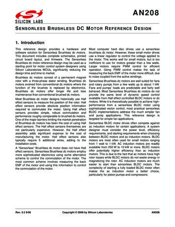
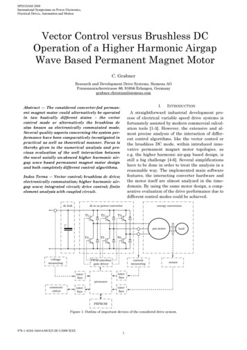
IJSRD - International Journal for Scientific Research & Development Vol. 3, Issue 03, 2015 ISSN (online): 2321-0613Sensorless Control of Brushless DC Motor using Zero Cross Back EMFDetection TechniqueMaqbul U. Ghanchi1 Dr. Saurabh N Pandya21Research Scholar 2Associate Professor1,2Department of Electrical Engineering1,2L.D. College of Engineering, Ahmedabad, IndiaAbstract— Normally, Brushless DC (BLDC) motor usesensors to detect the rotor position. But motor with sensorshave some limitations. To overcome these problems, anothercontrol technique for sensor less Brushless DC motorsuggest in this paper. Modeling and simulation of sensorless control of Permanent Magnet Brushless DC (PMBLDC)motor is carried out using zero-cross detection of back e.m.f.technique. Simulink is utilized with the help of MATLAB togive a very flexible and reliable simulation. Modeling ofBLDC motor in state space model to overcome thelimitations of transfer function based model. With statespace model representation, the motor performance can beanalyzed for variation of motor parameters. Results formotor three phase back e.m.f., three phase current, threephase torque and rotor speed get from simulation.Key words: Sensor less, BLDC Motor State Space Model,Zero Crossing DetectionI. INTRODUCTIONBrushless DC (BLDC) is one type of permanent magnetsynchronous machine. Recently much advancement inpermanent magnet materials, solid state devices and digitalcontrol techniques increase the efficiency of motor, betterpower factor and better dynamic performance [1,2]. Due tothese reasons BLDC motors are used so many applicationssuch as computers, printers and house hold appliances,electric vehicle, robotics etc. In BLDC motor electroniccommutation used rather than mechanical commutation inconventional DC motor. So BLDC motor needs invertercircuit and position sensors to detect the rotor position.Based on rotor position, inverter circuit switches actiontakes and commutates the motor line current in phase withcorresponding Back Electro Motive Force (BEMF). But theuse of sensors in BLDC motor have several limitations suchas it makes the motor body heavy, increasing size of motorand also complex wiring required which produces problemin interfacing the design, increase the cost, and increase thesize of the motor. Sensors less control of BLDC motor havemany advantages such as it has no problem of cleaning hallsensors after periodic interval [3]. BLDC motor withoutsensors can also be mounted in less accessible location.Motor with sensors below one watt power rating have lessefficiency due to power consumption in position sensors.PMBLDC motor operation without sensors using zero crossdetection technique modeled and simulated in MATLABSIMULINK [4].harmonic voltage (c) Detection of conducting interval offree-wheeling diodes connected in anti-parallel with thesolid-state switches (d) Monitoring the inductance variationin the d-q axes [1,5,6].The magnitude and polarity of line back e.m.f.change at the instant of zero crossing point. The zerocrossing of these e.m.f. give specific instants ofcommutation and can be used in the same way as Hall-effectsensor signals output to switch the devices in a particularsequence of power inverter [6]. Each transition occurs atevery 60 electrical degrees and thus there are sixcommutation instants in one cycleThe reliability of zero cross detection methoddepends on the measured signals of back e.m.f. voltages. Atthe time of motor starting, there is no back e.m.f. in motorand this control technique totally depends on the back e.m.f.of the motor. Means this method is suitable only when aminimum speed of about 5% of the rated speed is achieved.Hence, during starting time, the motor operates in open loopmode and is driven by the inverter which operates in 120degree conduction mode. When the motor reaches theminimum speed to facilitate zero-crossing detection of backe.m.f. the control is shifted to zero-crossing detection circuitand the drive operates in the closed loop mode.The sequence of operation of the motor duringstarting and running time can be seen in the block schematicdiagram as shown in Fig. 1.At the time of starting, the motor run in open loopmode due to BEMFs have not build up at sufficient level. Inthis mode motor supply input through by 120 degreeinverter block. After some time (threshold time), whenmotor has minimum 5% back e.m.f. of rated , than afterchanger block disconnects the 120 degree inverter block andmotor drives through logical inverter which is close loopmode. In close loop mode motor control through controllerblock and inverter opertate through it.II. DIFFERENT CONTROL STRATAGIESThe rotor position detection of the PMBLDC motor can beobtained using anyone of the four techniques. They are: (a)Detection of the line back e.m.f. voltages of motor (zerocrossing detection technique) (b) Detection of stator thirdAll rights reserved by www.ijsrd.com1669
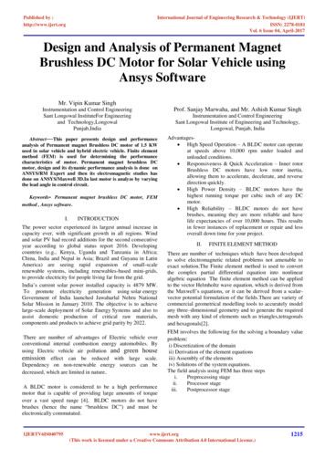
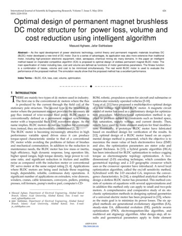
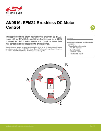
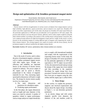
Sensorless Control of Brushless DC Motor using Zero Cross Back EMF Detection Technique(IJSRD/Vol. 3/Issue 03/2015/412) PERMANENT MAGNETBRUSHLESS DC MOTORVaVb LOADEcEb-X (t) [u (t) [ZERO V. SIMULINKDC POWERSUPPLY120 DEGREECONDUCTIONMODETIMER- ( )*(5)By using this five basic equations, state spaceequations for BLDC motor can be obtained which are givenbelow.̇ A X (t) B u (t)(6)EaVcCHANGER BLOCK(3)Fig. 1: Schematic Block Diagram for Sensor Less Operationof PMBLDC MotorA. Simulation of Zero Cross Detection:Zero crossing can be defined as a point where the sign of amathematical function changes (e.g. from positive tonegative), represented by a crossing of the axis (zero value)in the graph of the function. It is a commonly used term inelectronics, mathematics, sound, and image processingapplications. Simulation diagram for zero cross detectionshown in Fig. 3.III. MODELING OF BLDC MOTORThe mathematical model of BLDC motor is fundamental forcorresponding analysis of drives performance and design ofcontrol system for which is suitable to required performanceof the drives. For appropriate modeling, the structurecharacteristics and working modes of BLDC motor shouldbe considered. The modeling defined here is state space typemodeling which has certain advantages over transferfunction modeling [4, 5].Assumptions:The assumptions made for the development of PMBLDCmotor model are:1) Induced currents in the rotor due to stator areneglected2) Three phase star connected motor is considered3) Iron and stray losses are neglected4) The motor’s three phase are symmetric, includingtheir resistaaance, inductance and mutualinductances [7].Equivalent circuit of BLDCM is shown in fig. 2 whichhas three phase windings in star fashion. Each winding hasresistance Rs, inductance Ls and mutual inductance is L-M.Fig. 2: Equivalent Circuit of Stator WindingsThe stator three phase current changes with respectto time can be defined as (1) (2)Fig. 3: Simulation Diagram for Zero Cross DetectionB. Simulation of BLDC Motor:Simulation of BLDC motor is shown in fig. 4 [8]. Statespace modeling of BLDC motor is used in this simulationwhich is implemented in BLDC block. This simulation hasfive main blocks which are BLDC BLOCK, estimate block,controller block, inverter block and changer block.BLDC block contains two subsystems one is‘mybldc’ and another is ‘S-Function’. State space equationsof BLDC motor implement in this subsystem. The core ofthe state space model calculates the five variables I a, I b,I c, ω and θ.These variables are further processed to give atotal of 25 outputs that can be monitored.‘S-function’ presents a table that contains thesimulation constants like number of turns per phase, rotorlength etc. Appropriate values for these parameters shouldbe filled in S-function table.Logic used for controller block is that if the actualcurrent of phase U is less than actual current than transistorQ1 will be conduct. If actual current of phase U is more thanrequired current, than transistor Q1 will be turned off andAll rights reserved by www.ijsrd.com1670
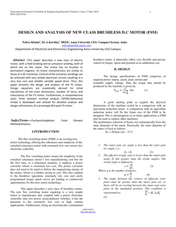
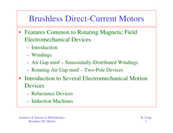
Sensorless Control of Brushless DC Motor using Zero Cross Back EMF Detection Technique(IJSRD/Vol. 3/Issue 03/2015/412)transistor Q4 will be turned on. Output of controller signalsare fed to the inverter circuit. The inverter ‘ALL PHASE’block consists of six transistor switches. PHASE U, PHASEV, PHASE W are the output of ‘ALL PHASE’ block whichare input for BLDC block via changer block.Fig. 4: Simulation of Brushless DC Motor with Zero Cross DetectionV. FLOWCHARTSequence of operation of BLDC motor simulation can beunderstood by referring the flowchart in the Fig. 5. Insimulation, the estimate block contains PID controller withthe values of Kp 16.61, Ki 0.0134 and Kd 0 which istuned by Ziegler Nichols method.This block calculates the reference phase current from thespeed and required torque. Required torque is calculated byactual speed and the speed error value. The above value willbe read and used in a PID controller [9]. The required torqueis calculated as follows, [E()] [(9)Fig. 5: Flowchart for Whole Control ProcessAll rights reserved by www.ijsrd.com1671
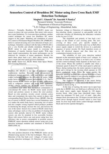
Sensorless Control of Brushless DC Motor using Zero Cross Back EMF Detection Technique(IJSRD/Vol. 3/Issue 03/2015/412)The required current is calculated from theinstantaneous required torque. Then this ’sTransformation to three phase currents. The approximatedpark’s transformation gives the corresponding phase currentto every stator phase according to the rotor’s position.Current34 ATorque0.9 N.mSelf inductance per winding2.72 mHNo. of turns per phase100Rotor radius20 cmMutual inductance between windings-1.5 mHFlux density0.8167 wbMotor inertia0.0002Rotor length30 cmCoulomb friction0.0178 NNumber of poles4Static friction0.089 NRotor radius20 cmWinding resistance per0.7 ΩPhaseTable 1: BLDC Motor ParametersFig. 7: Three Phase Current.VI. SIMULATION RESULTSThe simulation was run in MATLAB 6.5 [3] for0.20seconds (Simulation time). When the reference speedequals to 4000 rpm, the simulation curves of 3Φ back e.m.f.,3Φ current and rotor speed are shown in Fig. 6, 7, 8, andFig. 9.Fig. 8: Three Phase TorqueFig. 6: Three Phases BEMFFig. 9: Rotor SpeedVII. CONCLUSIONBLDC motor analysis based on state space model has beencarried out. Using zero cross detection technique, motorAll rights reserved by www.ijsrd.com1672
Sensorless Control of Brushless DC Motor using Zero Cross Back EMF Detection Technique(IJSRD/Vol. 3/Issue 03/2015/412)precise control can be achieved with low cost. State spacemodel has many advantages over transfer function model.The performance characteristics of the BLDCmotor can be evaluated for different machine parameters,which can be easily varied in the simulation study and it isuseful to get information of motor output. The simulationresults demonstrate that the simulated waveforms fittheoretical analysis well.REFERENCES[1] Jacek F. Gieras, Mitchell Wing: Permanent MagnetMotor Technology Design and Applications,Marcel Decker, Inc, 2002.[2] Duane, C. Hanselman. (1994): Brushlesspermanent-magnet motor design New York,McGraw-Hill.[3] 2003 Microchip Technology Inc., pp13[4] MATLAB 6.5, The Mathworks Inc., 2002[5] G.K.Dubey: Power Semiconductor Control Drives,Prentice-Hall, Eaglewood Cliffs, 1989[6] R.Krishnan: Electric Motor Drives Modeling,Analysis and Control, Prentice Hall of India PrivateLimited, New Delhi, 2002, pp 578-580.[7] Chee-Mun Ong: Dynamics of Electrical MachineryUsing MATLAB/ SIMULINK, Prentice Hall PTR,1998.[8] Figueroa, J.; Brocart, C.; Cros, J.; Viarouge, P.(2003): Simplified methods for ployphase brushlessDC motors. Mathematics and Computer inSimulation, 63 (3-5), pp. 209-224.[9] Palani, S. (2010): Contol system engineering.Second edition, McGraw Hill, India.All rights reserved by www.ijsrd.com1673
less control of Permanent Magnet Brushless DC (PMBLDC) motor is carried out using zero-cross detection of back e.m.f. technique. Simulink is utilized with the help of MATLAB to give a very flexible and reliable simulation. Modeling of BLDC motor in state space model to o