Transcription
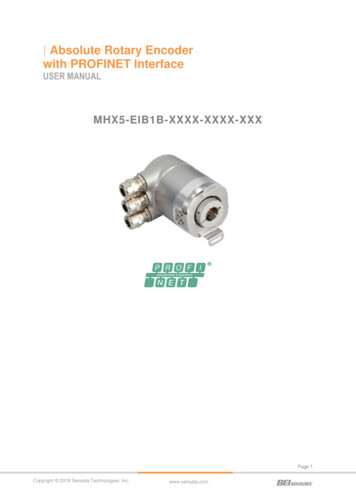
Absolute Rotary Encoderwith PROFINET InterfaceUSER MANUALMHX5-EIB1B-XXXX-XXXX-XXXPage 1Copyright 2018 Sensata Technologies, Inc.www.sensata.com
Content3.11 Rotary encoder function description . 22Content . 23.11.1 Code sequence . 221. Introduction. 43.11.2 Class 4 functionality . 221.1 Absolute rotary encoder . 43.11.3 Preset control for G1 XIST1 . 231.2 PROFINET technology. 53.11.4 Scaling function control . 231.3 Features of the Encoder. 53.11.5 Alarm channel control . 232. Installation. 62.1 Electrical Connection . 62.2 Ethernet cables . 62.3 Diagnostic LEDs . 72.4 Status LED indication . 72.5 Instructions for mechanical installation andelectrical connection of the rotary encoder. 83. Device configuration . 93.11.6 Compatibility mode . 233.11.7 Preset value . 243.11.7.1 Telegram 81-84 . 243.11.7.2 Telegram 860 . 263.11.8 Offset value . 263.11.9 Scaling parameters . 263.11.10 Max. Master Sign-Of-Life failures . 263.1 Standardization . 93.11.11 Velocity measuring units . 273.2 Encoder Classes . 93.11.12 Velocity filter . 273.3 Encoder functions . 103.11.13 Endless Shaft (RoundAxis) . 273.4 Signal list for Cyclic Data Transmission . 103.11.14 Encoder Profile version . 273.4.1 Format of actual position values . 113.4.2 Encoder control word (STW2 ENC) . 123.4.3 Encoder status word (ZSW2 ENC). 133.4.4 Encoder control word (G1 STW) . 133.4.5 Encoder status word (G1 ZSW) . 143.5 Standard manufacture telegrams . 153.6 Configuration principle . 173.7 Rotary encoder functionality overview. 174. Configuring with STEP7 . 284.1 Installing the GSDML file . 284.2 Engineering an encoder into a STEP7 project. 294.3 Module Access Point Parameter setup : 324.4 HW Config IRT-Setup: . 334.5 IRT- Topology. . 364.6 LLDP (Link Layer Discovery Protocol) . 364.7 SIMOTION SCOUT . 413.8 Rotary encoder functions – data format . 175 IRT communication . 493.9 Parameter for Acyclic Data Transmission185.1 IRT settings . 49Beginning with GSDML it is possible to changethe telegram type without changing the MAPparameters. . 185.2 User data reliability. 493.9.1 Base Mode Parameter . 195.2.2 Controller's Sign-Of-Life (C-LS) . 493.9.2 Device Parameter . 195.2.3 DO’s Sign-Of-Life (DO-LS) . 513.9.3 Vendor Parameter . 195.2.1 General . 495.2.4 Counting strategy for the Sign-Of-Life failurecounter . 533.10 Patronized Parameter . 19Page 2Copyright 2018 Sensata Technologies, Inc.www.sensata.com
ABSOLUTE ROTARY ENCODERWITH PROFINET INTERF ACEUSER MANUAL5.2.5 Error codes in G1 XIST2 . 545.3.5 Coding . 605.3 Base Mode Parameter Access . 545.3.6 Data flow . 645.3.1 General . 546. Configuring with TIA-Portal . 655.3.2 General characteristics . 547. Configuring with PC Worx . 678 FAQ . 735.3.3 DO addressing modes . 555.3.4 Parameter requests and parameterresponses . 559 Technical data, accessories and type keys7510 Glossary . 7711 Revision index . 78Page 3Copyright 2018 Sensata Technologies, Inc.www.sensata.com
ABSOLUTE ROTARY ENCODERWITH PROFINET INTERF ACEUSER MANUAL1. INTRODUCTIONThis manual describes the implementation andconfiguration of an absolute rotary encoder withPROFINET interface. The device fulfills therequirements of a PROFINET IO device with RT (realtime) or IRT (isochronous real time) classification.1.1 Absolute rotary encoderThe basic principle of an absolute rotary encoder is theoptical sampling of a transparent code disc which isfixed on the driving shaft.The absolute rotary encoder has a maximum resolutionof 65,536 steps per revolution (16 bits).The multi-turn versions can detect up to 16,384revolutions (14 bits). Therefore, the largest resultingresolution is 30 bits 230 1,073,741,824 steps. Thestandard single-turn version has 13 bits, the standardmulti-turn version 25 bits.For further information about the functioning principleor the setup of a PROFINET network please, refer toProfinet International (PI) at the following URLhttp://www.profibus.com/pn.Page 4Copyright 2018 Sensata Technologies, Inc.www.sensata.com
ABSOLUTE ROTARY ENCODERWITH PROFINET INTERF ACEUSER MANUAL1.2 PROFINET technologyPROFINET is an Industrial Ethernet standard mergingplant automation with other enterprise IT resources.PROFINET IO uses a view of distributed I/O similar toPROFIBUS DP. IO controllers (e.g. PLCs) run anIt provides comparable functionality to PROFIBUS withtechniques used by engineering, IT, and managementpersonnel.Established IT standards are employed as the basis ofcommunication: TCP, UDP, IP. XML are used asdescription languages for device profiles (GSDMLfiles).Two ways of using PROFINET are available:PROFINET IO, similar to PROFIBUS DP as adistributed I/O system and PROFINET CBA as amodular component-based system for larger systems.PROFINET offers scalable communication for differentapplications in industrial automation: PROFINET NRT (non real time) is suited fornon-time-critical process automation withclock rates of roughly 100 msec. PROFINET RT (real time) offers acommunication channel with optimizedperformance (10 msec clock rate) for mostfactory automation tasksautomation program, IO devices (e.g. absoluteencoders) are remotely assigned field devices, and IOsupervisors (e.g. programming devices) are used forcommissioning and diagnostics. PROFINET IRT (isochronous real time)employs special communication hardware toenable clock rates of less than 1 msec and ajitter precision of less than 1 µsec. Thischannel is mainly for use in motion controlapplications.The engineering of PROFINET IO is done similar toPROFIBUS. The field buses (i.e. Ethernet topologies)are assigned to control systems during configuration.The IO device is configured in the actual system basedon the contents of its GSDML file.After completion of the engineering the installer loadsthe data for the expansion into the IO controller (PLC)and the IO controller assumes data exchange with theIO device.An IO device is addressed within PROFINET (and alsopossibly by external IT components) through its IPaddress.Data can be exchanged from the IO controller to the IOdevice (and vice versa) cyclically (for process data).Apart from this, parameter data can be exchangedasynchronously during engineering of the IO device orby the use of PLC programming blocks.1.3 Features of the Encoder Integrated Boot loader for customerfirmware upgradesRound axis (Endless shaft)Neighboring detection Engineering identification callDifferent filters for velocityUsed Profinet Encoder Profile V4.0/V4.1Page 5Copyright 2018 Sensata Technologies, Inc.www.sensata.com
ABSOLUTE ROTARY ENCODERWITH PROFINET INTERF ACEUSER MANUAL2. INSTALLATION2.1 Electrical ConnectionThe rotary encoder is connected by a 4 pin M12connector for the power supply and two 4 pin,D-Coded M12 connectors for Ethernet.The Encoder uses a second D-coded connector andprovides integrated switch functionality. On or in thepackaging of the connector is the mountingdescription.Connector Ethernet4 pin female, D-codedConnector power supply4 pin male, A-codedPin NumberSignalPin NumberSignal1Tx 1US (10 - 30 V DC)2Rx 2N.C.3Tx -3GND (0V)4Rx Sketch on encoder view4N.C.23142.2 Ethernet cables2.2.1 RJ45 – M12 crossedSignalRJ45 Pin M12 Pin2.2.3 M12 – M12 crossedSignalM12 PinM12 PinTx 12Tx 11Tx-24Tx-22Rx 31Rx 33Rx-63Rx-442.2.2 RJ45 – M12 straightSignalRJ45 Pin M12 PinTx 11Tx-23Rx 32Rx-64Page 6Copyright 2018 Sensata Technologies, Inc.www.sensata.com
ABSOLUTE ROTARY ENCODERWITH PROFINET INTERF ACEUSER MANUAL2.3 Diagnostic LEDsLEDColorDescription for LED onActive1YellowIncoming and outgoing traffic at port 1Link1*GreenLink to another Ethernet component via port 1Active2YellowIncoming and outgoing traffic at port 2Link2*GreenLink to another Ethernet component via port 2Stat1GreenStatus 1, details see next tableStat2RedStatus 2, details see next table* Flashes with 2Hz if engineering identification call is activated and link connection is available2.4 Status LED indicationStatus 1GreenStatus 2Red(Bus failure)MeaningCauseOffOffNo powerFuse blown or cable defectOnOnNo connection to controllerCriteria: no data exchange- Bus disconnected- IO-Controller not availableswitched off / not in run/OnBlinking 1)Parameterization fault, no data - Slave not configured yet or able. - Wrong station address assignedHowever, the slave did not switch to(but not outside the permittedthe data exchange mode.range)- Actual configuration of the slavediffersfromthenominalconfigurationOnOffData exchange.Slave and operation ok.1)The blinking frequency is 0.5 Hz. Minimal indication time is 3 sec.Page 7Copyright 2018 Sensata Technologies, Inc.www.sensata.com
ABSOLUTE ROTARY ENCODERWITH PROFINET INTERF ACEUSER MANUAL2.5 Instructions for mechanical installation and electrical connection of the rotary encoderThe following points should be observed: Do not drop the encoder or subject it toexcessive vibration. The encoder is aprecision device. Do not open the encoder housing. If thedevice is opened and closed again, it canbe damaged and dirt may enter the unit. The encoder shaft must be connected tothe shaft to be measured through asuitable coupling (full shaft version). Thiscoupling is used to dampen vibrations andimbalance on the encoder shaft and toavoid inadmissible high forces. A variety ofsuitable couplings are available. Although absolute encoders are rugged,when used in tough ambient conditions,they should be protected against damageusing suitable protective measures. Theencoder should not be used as handles orsteps. Only qualified personnel may commissionand operate these devices. These arepersonnel who are authorized tocommission, ground and tag devices,systems and circuits according to thecurrent state of safety technology. It is not permissible to make any electricalchanges to the encoder. Route the connecting cable to the encoderat a considerable distance or completelyseparated from power cables with theirassociated noise. Completely shieldedcables must be used for reliable datatransfer and good grounding must beprovided. Cabling, establishing andinterrupting electrical connections mayonly be carried-out when the equipment isin a no-voltage condition. Short-circuits,voltage spikes etc. can result in erroneousfunctions and uncontrolled statuses whichcan even include severe personnel injuryand material damage. The encoder should have a solidconnection to power and ground. If theflange doesn’t have a good electricalconnection to the machine then it isacceptable to use a piece of copper tapeabout 30cm long and 2cm wide to get theproper connection.Before powering-up the system, check all of theelectrical connections. Connections, which are notcorrect, can cause the system to functionincorrectly. Fault connections can result in severepersonnel injury and material damage.Page 8Copyright 2018 Sensata Technologies, Inc.www.sensata.com
ABSOLUTE ROTARY ENCODERWITH PROFINET INTERF ACEUSER MANUAL3. DEVICE CONFIGURATION3.1 StandardizationThis actual generation of PROFINET devices isbased on the Encoder Profile V4.0/V4.1 (PNONo. 3.162). With this standardization it is possibleto substitute all products that fulfill thespecification. Refer to the next figure forexamples of suitable product connections thatmeet the Profinet connection criteria.3.2 Encoder ClassesApplication ClassDescription3Isochronous mode is not supported (RT)4Isochronous mode is supported (IRT)Page 9Copyright 2018 Sensata Technologies, Inc.www.sensata.com
ABSOLUTE ROTARY ENCODERWITH PROFINET INTERF ACEUSER MANUAL3.3 Encoder functionsImplementationFunctionClass 3Class 4-/ * G1 XIST1 Preset control-/ * Scaling function control-/ * Code sequenceClass 4 functionality -/ * --Measuring units per revolution / Measuring step-/ * Total measuring range-/ * Measuring units per revolution 64bit-/ * Total measuring range 64bit-/ * Maximum Master Sign-Of-Life failures-/ * Velocity measuring unit-/ * Encoder Profile version Operating time--Offset value-/ * Offset value 64 bit-/ * Round axis (Endless shaft) Velocity filter Alarm channel controlPreset valuePreset value 64bit* If Class 4 functionality is activated3.4 Signal list for Cyclic Data h (bit)3Master’s sign-of-lifeSTW2 ENC16-4Slave’s sign of lifeZSW2 ENC16-6Velocity value ANIST A16 8Velocity value BNIST B32 9Control wordG1 STW16-10Status wordG1 ZSW16-11Position value 1G1 XIST132-12Position value 2G1 XIST232-39Position value 3G1 XIST364-SignPage 10Copyright 2018 Sensata Technologies, Inc.www.sensata.com
ABSOLUTE ROTARY ENCODERWITH PROFINET INTERF ACEUSER MANUAL3.4.1 Format of actual position valuesG1 XIST1 and G1 XIST2 are the actual positionvalues in binary. For absolute encoders one The default setting is G1 XIST1 left aligned. P979, Subindex 3 (Shift factor for G1 XIST1) format example is given below. NOTE: thealignment in the data-frame (left or right-aligned)is considered for each individual resolution.32 – Total resolution (next binary value) G1 XIST1 send values independent Bit 10 instw2 and Bit 13 in g1 stw1Example: 25 bit Multi-turn absolute encoder(8192 steps per revolution, 4096 distinguishablerevolutions). All values are presented in binary formatG1 XIST2 displays the error telegram insteadof the right aligned position value if error occurs. The shifting factors in P979 "sensor format"display the actual format. P979, Subindex 4(Shift factor for G1 XIST2) 0 The settings in the Encoder parameter dataaffect the position value in both G1 XIST1 andG1 XIST2.Case Encoder Profile 4.1* The default setting is G1 XIST1 right aligned. If a 32bit counter starts with the absoluteposition value. After increasing maximumcounter value start again with 0 or after 0decreasing to the maximum counter value P979, Subindex 3 (Shift factor for G1 XIST1) 0 G1 XIST1 send values independent Bit 10 instw2 and Bit 13 in g1 stw1* Profile 4.0 realized with GSDML-V2.2POSITAL-OCD-20100808, Profile 4.1 with newerfilesM Distinguishable Revolutions (Multi-turnvalue)S Pulses (Single-turn steps per revolution)Case Encoder Profile 7MMMMMMMMMMMMSSSSSSSSSSSSS6543210Absolute value in G1 XIST1 for Encoder Profile 6543210MMMMMMMMMMMMMMMMMMMSSSSSSSSSSSSS“Absolute value” in G1 XIST1 for Encoder Profile 6543210MMMMMMMMMMMMSSSSSSSSSSSSSAbsolute value in G1 XIST2Page 11Copyright 2018 Sensata Technologies, Inc.www.sensata.com
ABSOLUTE ROTARY ENCODERWITH PROFINET INTERF ACEUSER MANUALG1 XIST3For 64bit position values is the G1 XIST3 available. The binary value will transmit right aligned and without shiftingfactor.IO Data1Format23464 bit position value3.4.2 Encoder control word (STW2 ENC)4-Bit-counter, left justified. The master applicationstarts the sign of life with any value between 1and 15. The master increases the counter inevery cycle of the master application. Valid valuesfor the master’s sign of life are 1 to 15, “0”indicates an error and is left out in normaloperation.ImplementationBitFunction0 9Reserved, currently not used10Control by PLC11Reserved, currently not used12 15Controller Sign-Of-LifeClass 3Class 4 - BitValueSignificanceComments101Control by PLCControl via interface, EO IO Data is valid0No control by PLCEO IO Data is not valid. Except Sign-Of-LifeController Sign-Of-LifeSend continuous counting value from 0 to 1512 15Page 12Copyright 2018 Sensata Technologies, Inc.www.sensata.com
ABSOLUTE ROTARY ENCODERWITH PROFINET INTERF ACEUSER MANUAL3.4.3 Encoder status word (ZSW2 ENC)4-Bit-counter, left justified. The slave applicationapplication in every DP-cycle. Valid values for thestarts the sign of life with any value between 1and 15 after successful synchronization to theclock pulse. The counter is increased by the slaveslave’s sign of life are 1 to 15, “0” indicates anerror and is left out in normal operation.ImplementationBitFunction0 8Reserved, currently not used9Control requested10 11Reserved, currently not used12 15Encoder Sign-Of-LifeClass 3Class omments91Control requestedThe automation system is requested to assume control0No control by PLCEO IO Data is not valid. Except Sign-Of-LifeEncoder Sign-Of-LifeSend back continuous Controller Sign-Of-Life (countingvalue from 0 to 15)12 153.4.4 Encoder control word (G1 STW)BitValueFunction0.10CommentsReserved, currently not used110/1„Home position mode“121Set preset / request shift Preset (resp. shift) is set when changing this Bit to “1” (risingedge). Default preset value (shift): 0Warning: After setting the preset the offset will be save in thenonvolatile memory. In this 5-10ms the encoder will not sendposition values.131Request absolute valuecyclicallyRequest of additional cyclic transmission of the absolute actualposition in G1 XIST2. If no other data needs to be transferreddue to commands or errors the absolute position value will betransmitted automatically.141Activate parking sensorIf the “activate parking sensor” bit is set, the encoder transmitsno error messages.151Acknowledging a sensor Request to acknowledge / reset a sensor errorerrorSpecifies if the position value shall be set to a previouslyprogrammed absolute value or shifted by this value.0: set home position / preset (absolute)1: shift home position / preset (relative offset)Page 13Copyright 2018 Sensata Technologies, Inc.www.sensata.com
ABSOLUTE ROTARY ENCODERWITH PROFINET INTERF ACEUSER MANUAL3.4.5 Encoder status word (G1 ZSW)BitValueMeaning0.10CommentReserved, currently not used11Acknowledgementsensor error in processIs set if the reset of a sensor error (after acknowledging) takeslonger than one bus cycle.121Set preset / shiftAcknowledgement for “set preset / request shift”reference point executed131Transmit absolute valuecyclically141Parking sensor activated Acknowledgement for “activate parking sensor”. The encodertransmits no error messages.151Sensor errorAcknowledgement for “request absolute value cyclically”Indicates a sensor error. A device specific error code istransmitted in G1 XIST2.Page 14Copyright 2018 Sensata Technologies, Inc.www.sensata.com
ABSOLUTE ROTARY ENCODERWITH PROFINET INTERF ACEUSER MANUAL3.5 Standard manufacture telegramsStandard Telegram 81IO Data (DWord)1SetpointSTW2 ENC* G1 STW1*2* Details about the variables are available in chapter 3.4IO Data 1(DWord)Actualvalue245ZSW2 ENC* G1 ZSW1* G1 XIST1*Standard Telegram 82IO Data (DWord)1Setpoint6G1 XIST2*2STW2 ENC* G1 STW1*IO Data 1(DWord)Actualvalue32345ZSW2 ENC* G1 ZSW1* G1 XIST1*67G1 XIST2*NIST A*57Standard Telegram 83IO Data (DWord)1SetpointSTW2 ENC* G1 STW1*IO Data 1(DWord)Actualvalue224ZSW2 ENC* G1 ZSW1* G1 XIST1*Standard Telegram 84IO Data (DWord)1Setpoint6G1 XIST2*NIST B*7982STW2 ENC* G1 STW1*IO Data 1(DWord)Actualvalue323456ZSW2 ENC* G1 ZSW1* G1 XIST3*8G1 XIST2*10NIST B*Page 15Copyright 2018 Sensata Technologies, Inc.www.sensata.com
ABSOLUTE ROTARY ENCODERWITH PROFINET INTERF ACEUSER MANUALManufacture Telegram 860With this telegram it is not necessary to set specialbits to get cyclic data transmission. It is openaccording to the Profibus functionality and is an easy way to set a customer preset value while thePLC is running. The velocity value uses the formatthat is defined in the Velocity measuring unit.No control wordNo Status wordNo Life Sign monitoring.Output: 32 Bit-Unsigned Preset value (Bit 31 Preset-Control , less than Total Resolution)Input: 32 Bit-Unsigned Position Value 32 Bit-Integer Velocity ValueInput Data (Input data from Encoder to Controller): 8 BytesPosition value - 32 Bit Unsigned IntegerByte 0Byte 1Byte 2MSBVelocity value - 32 Bit Signed IntegerByte 3Byte 4LSBMSBByte 5Byte 6Byte 7LSBOutput Data (Output data from Controller to Encoder): 4 BytesPreset - 32 Bit Unsigned IntegerBit 31Bit 30 .Bit 0Preset ControlPreset value Total ResolutionPage 16Copyright 2018 Sensata Technologies, Inc.www.sensata.com
ABSOLUTE ROTARY ENCODERWITH PROFINET INTERF ACEUSER MANUAL3.6 Configuration principleThe rotary encoder with PROFINET interface canencoder has to be installed in the used PLCbe programmed according to the needs of theuser. The GSDML file pertaining to the rotaryengineering software tool.3.7 Rotary encoder functionality overviewFunctionCommunication channelPosition valueCyclic input (IO device - IO controller)PresetCyclic output (IO controller - IO device)Coding sequenceAcyclic input/outputScaling functionAcyclic input/output3.8 Rotary encoder functions – data formatPROFINET IO devices are set up in modules. Eachmodule can be plugged in physical and/or logicalslots. These are subdivided into sub slotsindividually to accommodate further data hierarchy.One sub slot can contain several cyclic input/outputchannels as well as acyclic record channels (usedfor parameters).PLCs there are in the GSDML-file two directories:Standard and Encoder Profile 4.Rotary encoders offer for the standard profile oneslot (address #0) with one sub slot (address #0) forall device data for old PLC’s that don’t supportseveral sub slots.Device parameters are grouped together as recordsThere are two versions of PLC available. Some ofthem support only one sub slot. Other ones i.e. S7400 support several sub slots. To work with bothin the PROFINET interface. The following tablegives an overview of the rotary encoder’s datachannels.GSDML fileRotary encoderAcyclic datatransmission(Parameters)PLC engineering softwareCyclic datatransmission(process data)PLCPage 17Copyright 2018 Sensata Technologies, Inc.www.sensata.com
ABSOLUTE ROTARY ENCODERWITH PROFINET INTERF ACEUSER MANUAL3.9 Parameter for Acyclic Data TransmissionThe user parameter data is sent to the encoder in thePROFIdriveparametersandencoderspecificstart-up phase as a Record Data Object using the datarecord 0xBF00. For the mapping of the differentencoder functions into the user data section of theRecord Data Object. In addition to the parameter dataconfiguration the encoder supports a number ofparameters accessible via the Acyclic Data Exchangeservice.Beginning with GSDML it is possible to changethe telegram type without changing the MAPparameters.Page 18Copyright 2018 Sensata Technologies, Inc.www.sensata.com
ABSOLUTE ROTARY ENCODERWITH PROFINET INTERF ACEUSER MANUAL3.9.1 Base Mode ParameterFunctionSlotSub slotIndexOffsetLengthIOCode sequence110xBF000.01 Bit-Class 4 functionality110xBF000.11 Bit-G1 XIST1 Preset control110xBF000.21 Bit-Scaling function control110xBF000.31 Bit-Alarm channel control110xBF000.41 Bit-Compatibility mode110xBF000.51 Bit-Measuring units per revolution110xBF0018 Byte-Total measuring range110xBF0098 Byte-Maximum Master Sign-Of-Life failures110xBF00171 Byte-Velocity measuring unit110xBF00181 Byte-FunctionSlotSub slotIndexOffsetLengthPreset value110xB02EVia Parameter Number 65000FunctionSlotSub slotIndexOffsetLengthVelocity filter110x100001 Byte3.9.2 Device ParameterIO-3.9.3 Vendor ParameterIO-3.10 Patronized ParameterAccording to the Profidrive profile the followingparameters are availableRecord Read-Write Index : 0xB02ECreate Parameter Request Program: (example:Parameter Read)Avoid splitting tables across pagesNumberParameterRead only922Telegram selection925Number of life sign failures that may be tolerated964Drive Unit identification 965Profile identification number 971Transfer into a nonvolatile memory975DO identification 979Sensor format 980Number list of defined parameter 65000Preset65001Operating statusRead/Write Page 19Copyright 2018 Sensata Technologies, Inc.www.sensata.com
ABSOLUTE ROTARY ENCODERWITH PROFINET INTERF ACEUSER MANUALParameter modelPage 20Copyright 2018 Sensata Technologies, Inc.www.sensata.com
ABSOLUTE ROTARY ENCODERWITH PROFINET INTERF ACEUSER MANUALSample of configuration according to Encoder Profile V4.1Page 21Copyright 2018 Sensata Technologies, Inc.www.sensata.com
ABSOLUTE ROTARY ENCODERWITH PROFINET INTERF ACEUSER MANUAL3.11 Rotary encoder function descriptionDetails of this functionality are available on the nextpages.ImplementationFunctionClass 3Code sequenceClass 4DescriptionChapter-/ * 3.11.1 3.11.2G1 XIST1 Preset control-/ * 3.11.3Scaling function control-/ * 3.11.4Alarm channel control 3.11.5Compatibility mode 3.11.6-/ * 3.11.7Class 4 functionalityPreset valuePreset value 64bit---Measuring units per revolution / Measuring step-/ * 3.11.9Total measuring range-/ * 3.11.9Measuring units per revolution 64bit-/ * -Total measuring range 64bit-/ * -Maximum Master Sign-Of-Life failures-/ * 3.11.10Velocity measuring unit-/ * 3.11.11Encoder Profile version 3.11.14Operating time---Offset value-/ * 3.11.8Offset value 64 bit-/ * -Round axis (Endless shaft) 3.11.13Velocity filter 3.11.12* If Class 4 functionality is activated3.11.1 Code sequenceThe parameter “code sequence“ defines thecounting direction of the position value. The codeincreases when the shaft is rotating clockwise (CW)or counter-clockwise (CCW) (viewingthe shaft).Code sequenceDirection of rotation when viewing the shaftCode sequence0 (default)Clockwise (CW)Increasing1Counter-clockwise (CCW)Decreasing3.11.2 Class 4 functionalityThe parameter “Class 4 functionality“ defines thatthe scaling, preset and code sequence affects theposition value in G1 XIST1, 2 and 3.Class 4 controlClass 4 function0 (default)Deactivated1ActivatedPage 22Copyright 2018 Sensata Technologies, Inc.www.sensata.com
ABSOLUTE ROTARY ENCODERWITH PROFINET INTERF ACEUSER MANUAL3.11.3 Preset control for G1 XIST1The parameter “preset control” defines the presetPreset control is disabled then the Preset will not befunctionality. If parameter Class 4 is activated andaffected for G1 XIST1.Preset controlPreset function1Preset does not affect G1 XIST10 (default)G1 XIST1 is affected by a Preset command3.11.4 Scaling function controlThe parameter “scaling function control” enable /disable the scaling function. If not, the physicalScaling function controlScaling function0Deactivated1 (default)Activatedposition value is returned by the rotary encoder.This is only available if class 4 control is activated.3.11.5 Alarm channel controlThe parameter “Alarm channel control” defines thelength of diagnostic telegram. If the Alarm channelAlarm channel controlAlarm channel function0 (default)Deactivated1Activatedis deactivated then it will only transmit the first 6bytes of the diagnostic telegram.3.11.6 Compatibility modeThis parameter defines if the encoder should run ina mode compatible to Version 3.1 of the EncoderProfile. See next tables for an overview of thefunctions affected when the compatibility mode isenabled.Compatibility modeCompatibility functionMeaning0EnableCompatibility with Encoder Profile V3.11 (default)DisableNo backward compatibilityPage 23Copyright 2018 Sensata Technologies, Inc.www.sensata.com
ABSOLUTE ROTARY ENCODERWITH PROFINET INTERF ACEUSER MANUALFunctionCompatibility mode Enable ( 0)Compatibility mode Enable ( 1)Control by PLCIgnored; the Control word (G1 STW)Supported(STW2 ENC)and setpoint values are always valid.Control requested (ZSW2 ENC) is notsupported and is set to 0Userparameter“MaximumMasterSign-Of-Life failures”SupportedNot supported; one Sign-Of-Life failuretolerated, P925 is optional to controlthe life sign monitoringUser parameter “Alarmchannel control”SupportedNot supported; the application alarmchannel is active and controlled by aPROFIdrive parameterP965 - Profile version31 (V3.1)41 (V4.1)3.11.7 Preset value3.11.7.1 Telegram 81-84With the Preset value it is possible to adapt the encoderzero point to the zero point of the application. Whenusing this function the current encoder position value isset to the desired preset value. The integrated microcontroller
1.1 Absolute rotary encoder The basic principle of an absolute rotary encoder is the optical sampling of a transparent code disc which is fixed on the driving shaft. The absolute rotary encoder has a maximum resolution of 65,536 steps per revolution (16 bits). The multi-turn versions can detect up to 16,384 revolutions (14 bits).
