Transcription
ESRS – EncoderSignal ReferenceSimulator(Cat. No. 4100-ESRS)Installation and Setup Manual
Important User InformationBecause of the variety of uses for the products described in thispublication, those responsible for the application and use of thiscontrol equipment must satisfy themselves that all necessary stepshave been taken to assure that each application and use meets allperformance and safety requirements, including any applicable laws,regulations, codes and standards.The illustrations, charts, sample programs and layout examples shownin this guide are intended solely for purposes of example. Since thereare many variables and requirements associated with any particularinstallation, Allen-Bradley does not assume responsibility or liability(to include intellectual property liability) for actual use based uponthe examples shown in this publication.Allen-Bradley publication SGI-1.1, Safety Guidelines for theApplication, Installation and Maintenance of Solid-State Control(available from your local Allen-Bradley office), describes someimportant differences between solid-state equipment andelectromechanical devices that should be taken into considerationwhen applying products such as those described in this publication.Reproduction of the contents of this copyrighted publication, in wholeor part, without written permission of Rockwell Automation, isprohibited.Throughout this manual we use notes to make you aware of safetyconsiderations:ATTENTION!Identifies information about practices orcircumstances that can lead to personal injury ordeath, property damage or economic lossAttention statements help you to: identify a hazard avoid a hazard recognize the consequencesIMPORTANTIdentifies information that is critical for successfulapplication and understanding of the product.Allen-Bradley is a trademark of Rockwell Automation
European Communities (EC)Directive ComplianceIf this product has the CE mark it is approved for installation withinthe European Union and EEA regions. It has been designed andtested to meet the following directives.EMC DirectiveThis product is tested to meet the Council Directive 89/336/ECElectromagnetic Compatibility (EMC) by applying the followingstandards, in whole or in part, documented in a technicalconstruction file: EN 50081-2 EMC — Generic Emission Standard, Part 2 —Industrial Environment EN 50082-2 EMC — Generic Immunity Standard, Part 2 —Industrial EnvironmentThis product is intended for use in an industrial environment.Low Voltage DirectiveThis product is tested to meet Council Directive 73/23/EEC LowVoltage, by applying the safety requirements of EN 61131-2Programmable Controllers, Part 2 - Equipment Requirements andTests. For specific information required by EN 61131-2, see theappropriate sections in this publication, as well as the Allen-Bradleypublication Industrial Automation Wiring and Grounding GuidelinesFor Noise Immunity, publication 1770-4.1.This equipment is classified as open equipment and must bemounted in an enclosure during operation to provide safetyprotection.
Table of ContentsPrefaceUsing This ManualRead This Manual . . . . . . . . . . . . . . . . . . .Who Should Use this Manual. . . . . . . . . . .Purpose of this Manual . . . . . . . . . . . . . . .Safety Precautions . . . . . . . . . . . . . . . . . . .Contents of this Manual . . . . . . . . . . . .Related Documentation . . . . . . . . . . . .Terminology . . . . . . . . . . . . . . . . . . . . . . .Common Techniques Used in this Manual .Product Receiving & Storage ResponsibilityAllen-Bradley Support . . . . . . . . . . . . . . . .Local Product Support . . . . . . . . . . . . .Technical Product Assistance . . . . . . . .On the Web . . . . . . . . . . . . . . . . . . . . . . .Chapter 21-31-41-41-41-41-41-51-51-5OverviewESRS Description. . . . . . . . . . . . .Principal features of the ESRS .ESRS Front Panel. . . . . . . . . . . . .ESRS Footprint . . . . . . . . . . . . . .ESRS Principal Specifications . . . .Mechanical Specifications . . . .Environmental Specifications .Power Supply and Fuses . . . . . . .Power Supply Specifications. .Quadrature Output . . . . . . . .Index Pulse . . . . . . . . . . . . . .I/O Filtering . . . . . . . . . . . . .Chapter 2.InstallationMounting the ESRS . . . . . . . . . . . . . . . . . . . . . . . . . . . . . . 2-2Enable Input. . . . . . . . . . . . . . . . . . . . . . . . . . . . . . . . . . . 2-2External Power Supply . . . . . . . . . . . . . . . . . . . . . . . . . . . 2-6iPublication 4100-IN505A-EN-P - October 2000
iiChapter 3OperationGeneral . . . . . . . . . . . . . . . . . . . . . . .Indicators . . . . . . . . . . . . . . . . . . . . . .Controls . . . . . . . . . . . . . . . . . . . . . . .Line Speed . . . . . . . . . . . . . . . . . .When Set To Unidirectional. . . . .When Set To Bi-directional . . . . .Acceleration. . . . . . . . . . . . . . . . . .Rounding . . . . . . . . . . . . . . . . . . .Line Selection . . . . . . . . . . . . . . . .Inputs and Outputs . . . . . . . . . . . . . . .Line Speed Ref Out . . . . . . . . . . . .Strobe Out. . . . . . . . . . . . . . . . . . .Ext Line Speed In. . . . . . . . . . . . . .P1 . . . . . . . . . . . . . . . . . . . . . . . . .Enable Voltage . . . . . . . . . . . . . .Enable Input. . . . . . . . . . . . . . . .Direction Output . . . . . . . . . . . .P2 . . . . . . . . . . . . . . . . . . . . . . . . .Options Switch . . . . . . . . . . . . . . . . . .Setting the Option Switch. . . . . . . .Mode Selection . . . . . . . . . . . . . .Index Division Ratio Selection . . .Maximum Effective Motor Speed .IndexPublication 4100-IN505A-EN-P - October 3-53-53-63-63-73-73-83-8
PrefaceRead This ManualRead and understand this instruction manual. It provides thenecessary information to let you install, connect, and set up theEncoder Signal Reference Simulator for safe, reliable operation. Thispreface covers the following topics: Who should use this manual The purpose of this manual Terminology Common techniques used in this manual Allen-Bradley supportWho Should Use thisManualYou should read this manual if you are responsible for the installationor set up of the Encoder Signal Reference Simulator.If you do not have a basic understanding of the products listed below,contact your local Allen-Bradley representative for information onavailable training courses before using this product. S Class Compact motion controller 1394 GMC System modulePurpose of this Manual1This manual is an installation and set up guide for the Encoder SignalReference Simulator. It describes the procedures necessary to properlyinstall and configure it into your motion control system.Publication 4100-IN505A-EN-P - October 2000
PrefaceP-2Safety PrecautionsThe following general precautions apply to the Encoder SignalReference Simulator:ATTENTION!Electric shock can kill. Make sure the Encoder SignalReference Simulator is safely installed in accordancewith the Installation and Set-up chapters of thismanual. Avoid contact with electrical wires andcabling while power is on. Only trained servicepersonnel should open the electrical cabinet.This product contains stored energy devices. Toavoid hazard of electrical shock, verify that allvoltage on the capacitors has been discharged beforeattempting to service, repair, or remove this unit. Youshould only attempt the procedures in this manual ifyou are qualified to do so and familiar withsolid-state control equipment and the safetyprocedures in publication NFPA 70E andBS-EN60204.The system integrator is responsible for local safetyand electrical codes.ATTENTION!Publication 4100-IN505A-EN-P - October 2000An incorrectly applied or installed product canresult in component damage or a reduction inproduct life. Wiring or application errors, such asundersizing or inadequate DC supply, or excessiveambient temperatures can result in a malfunction.The Encoder Signal Reference Simulator containsESD (Electrostatic Discharge) sensitive parts andassemblies. Static control precautions are requiredwhen installing, testing, servicing, or repairing thisassembly. Component damage can result if ESDcontrol procedures are not followed. If you are notfamiliar with static control procedures, refer toAllen-Bradley publication 8000-4.5.2, GuardingAgainst Electrostatic Damage or any otherapplicable ESD Protection Handbook.
PrefaceP-3Contents of this erationContentsDescribes the purpose, background, and scopeof this manual. Also specifies the audience forwhom this manual is intended.Provides a general description of the EncoderSignal Reference Simulator, its features andmechanical specifications.Provides the steps needed to successfullymount and wire the Encoder Signal ReferenceSimulator.Provides information on using the ESRS.Related DocumentationThe following documents contain additional information concerningrelated Allen-Bradley products. To obtain a copy, contact your localAllen-Bradley office or distributor.ForInstructions for installation and set-up for the 1394 GMCsystemInstructions for installation and set-up for the S ClassCompact motion controllerInstructions for using the Ultra PlusAn article on wire sizes and types for grounding electricalequipment (North American standards)Read This Document1394 Digital, AC, Multi-Axis Motion ControlSystem User ManualIMC S Class Compact Motion ControllerInstallation and Set-up Manual1398 Ultra Plus User ManualNational Electrical CodeAn article on wire sizes and types for grounding electricalequipment (European standards).A complete listing of current Allen-Bradley documentation,including ordering instructions. Also indicates whether thedocuments are available on CD-ROM or in multi-languagesA glossary of industrial automation terms and abbreviationsBS-EN 60204 Electrical Equipment ofMachinesAllen-Bradley Publication IndexTerminologyDocument Number1394-5.0999-1221398-5.1Published by theNational FireProtectionAssociation ofBoston, MA.Published by BritishStandards InstituteSD499Allen-Bradley Industrial Automation Glossary AG-7.1In order to avoid confusion, we have used the following general termsin a specific manner within this manual. We define them as follows:ESRS - Refers to the Encoder Signal Reference Simulator.Publication 4100-IN505A-EN-P - October 2000
PrefaceP-4For specific definitions of other terms used in industrial automation,see the Allen-Bradley Industrial Automation Glossary (publicationnumber AG-7.1).Common Techniques Usedin this ManualThe following conventions are used throughout this manual: Bulleted lists such as this one provide information, notprocedural steps. Numbered lists provide sequential steps or hierarchicalinformation. When we refer you to another location, the section nameappears in italics. The exclamation point inside of a triangle, followed by the word“ATTENTION” indicate circumstances that can lead to personalinjury, death, property damage or economic loss. See examplebelow.ATTENTION!Failure to observe these warnings may cause damageto the unit, unexpected and/or uncontrolledmovement of peripheral equipment, and your healthand safety. An important table indicates critical information. See thefollowing example.IMPORTANTProduct Receiving &Storage ResponsibilityPublication 4100-IN505A-EN-P - October 2000Identifies information that is critical for successfulapplication and understanding of the product.You, the customer, are responsible for thoroughly inspecting theequipment before accepting the shipment from the freight company.Check the item(s) you receive against your purchase order. If anyitems are obviously damaged, it is your responsibility to refusedelivery until the freight agent has noted the damage on the freightbill. Should you discover any concealed damage during unpacking,you are responsible for notifying the freight agent. Leave the shippingcontainer intact and request that the freight agent make a visualinspection of the equipment.
PrefaceP-5Leave the product in its shipping container prior to installation. If youare not going to use the equipment for a period of time, store it: in a clean, dry location within an ambient temperature range of 0 to 85 C (32 to 185 F) within a relative humidity range of 5% to 95%, non-condensing in an area where it cannot be exposed to a corrosiveatmosphere in a non-construction areaAllen-Bradley SupportAllen-Bradley offers support services worldwide, with over 75 Sales/Support Offices, 512 authorized Distributors and 260 authorizedSystems Integrators located throughout the United States alone, plusAllen-Bradley representatives in every major country in the world.Local Product SupportContact your local Allen-Bradley representative for: sales and order support product technical training warranty support support service agreementsTechnical Product AssistanceIf you need to contact Allen-Bradley for technical assistance, pleasereview the information in this manual first. Then call your localAllen-Bradley representative. For the quickest possible response, werecommend that you have the catalog numbers of your productsavailable when you call. See the Related Documentation section ofthis chapter for the publication numbers of other manuals that canhelp with this product.Publication 4100-IN505A-EN-P - October 2000
PrefaceP-6The Rockwell Automation Technical Support numbers are:in Europe: ( 44) 1270 580142in North America (603) 443-5419On the WebFor information about Allen-Bradley, visit the following World WideWeb site:http://www.ab.com/Publication 4100-IN505A-EN-P - October 2000
Chapter1OverviewESRS DescriptionThe Encoder Signal Reference Simulator (ESRS) generates a digitalspeed reference for a motor and encoder feedback combination. Inpractice the ESRS would be connected to the Master Encoder input ofa drive. The ESRS then generates quadrature pulses with selectableindex (i.e. marker) which a drive forces its motor/encoder to follow.The ESRS operates in either unidirectional or bi-directional mode asselected by the Options switch located on the printed circuit board(PCB) of the ESRS. The rounding and acceleration functions areoperational in all modes and for all inputs including STOP.Principal features of the ESRS Selectable Internal and External Line Reference inputs plus Stop. Separate Enable input, with status indication, allows for remotecontrol. Rate of acceleration and deceleration continuously variablebetween 1.5 and 15 seconds. Five positions of rounding plus “OFF”. Powered with a single 5V or 12V DC input voltage taken fromeither the drive’s Encoder connector or external power supply. User selectable Index pulse in the range 210, 211, 212, 213 counts. Motor speed selectable in the range 1875 to 15000 RPM. Product housed in a rugged steel box with mounting tabs. Operates in Unidirectional and Bi-directional mode. Separate square wave “STROBE” output, which is synchronizedwith the Index pulse, for triggering stroboscopes, oscilloscopes,and so forth. Analog output indication of commanded speed.1Publication 4100-IN505A-EN-P - October 2000
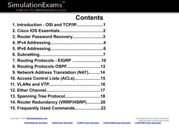
1-2Overview Digital output indicates phase of quadrature pulse train (i.e.direction of motor rotation).ESRS Front PanelThe following illustration shows the placement and labelling of majoritems on the ESRS front panel.Figure 1.1 ESRS Front Panel LayoutPublication 4100-IN505A-EN-P - October 2000
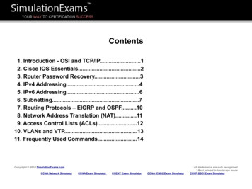
OverviewESRS Footprint1-3The following figure shows the footprint of the ESRS with fixing holedimensions and drilling details.Figure 1.2 ESRS DimensionsPublication 4100-IN505A-EN-P - October 2000
1-4OverviewESRS PrincipalSpecificationsMechanical SpecificationsTable 1.A Mechanical SpecificationsEnclosure TypeSteel case with integral mounting feet on rear edge.Enclosure SizeEnglish (inch)11.6 x 13.5 x 1.7Metric (mm)295 x 343 x 43Environmental SpecificationsTable 1.B Environmental SpecificationsOperatingPower Supply and FusesStorageTemperature0 to 60oCHumidity95% non condensing @ 60oC-40 to 70oCPower Supply SpecificationsTable 1.C Power SpecificationsInput Voltage 5 or 12V DC. Both 5%Current DrawApproximately 0.6A DCOvercurrent ProtectionOvercurrent protection is provided byseparate 5V (F102) and 12V (F103) PCBmounted fuses rated at T1.6A. A sparefuse (F101) is also provided on the PCB.If 5V and 12V are appliedsimultaneously, the ESRS selectsthe 12V input.The ESRS is intended to take itspower from the encoder supply ofthe target equipment. However, theuser should establish that thissupply has sufficient capacity toprovide the current indicated above.If necessary, an additional powersupply is required – see Chapter 2:Installation.Publication 4100-IN505A-EN-P - October 2000
Overview1-5Quadrature OutputTable 1.D Quadrature OutputNumber of quadrature outputs provided.OneOutput formatIncremental quadrature with Index pulse.Output data typeRS422 TTL Levels.Quadrature output frequency0 to 275kHz.Quadrature output phaseForward is defined as A phase leading B.Reverse is defined as B phase leading A.Index PulseTable 1.E Index PulseIndex division ratios.Selectable in the range : 210, 211, 212, 213pulses.Index pulse typeGatedThe index pulse is high (Logic 1 orTrue) only when the selecteddivision ratio has been satisfied andthe A and B phases are High.I/O FilteringTable 1.F I/O FilteringHigh Frequency Filtering.High Frequency filtering is provided on allpower, digital and analog I/O lines asappropriate.Over-Voltage ClampingOver-voltage clamping is provided on thepower supply inputs, the quadrature andindex outputs, and the “EXT LINE SPEEDIN” input.Publication 4100-IN505A-EN-P - October 2000
1-6OverviewPublication 4100-IN505A-EN-P - October 2000
Chapter2InstallationThe ESRS is designed to be mounted in an electrical cabinet via themounting tabs on its back panel. For all applications, this installationmethod should be observed. Before powering up your ESRS, makesure it has been configured correctly and that all peripheralequipment has been correctly connected to it.ATTENTION!Do not apply power to your ESRS when it is part of acontrol system without first establishing that this willnot have any adverse effects.Do not make or break any electrical connections toyour ESRS while power is applied.Do not change any option switch settings on yourESRS while power is applied.Failure to observe the above warnings may causeimmediate and uncontrolled movement of controlledhardware, damage to the ESRS, peripheralequipment, and your health and safety.The following safety points must be observed when installing the unit: The 5V or 12V DC supply must be electrically isolated from allother supplies with higher potentials. The 0V (common) side of the 24V DC supply must be connectedto a safety ground. The unit is intended for installation and use within an electricalcontrol cabinet in a normal industrial environment. When used in an electrical cabinet, the case of the ESRS must bebonded to the cabinet via the mounting feet.1Publication 4100-IN505A-EN-P - October 2000
2-2InstallationMounting the ESRSThe ESRS must be properly grounded to the metal enclosure panel.The following diagram shows how to ground the ESRS to the panel.Figure 2.1 Mounting and Grounding DiagramEnable InputThere are several ways in which the Enable Input can be wired. Thediagrams on the following pages indicate the various connectionoptions.The following diagram shows how to connect the ESRS to continuallyenable the device from the internal Enable supply.Publication 4100-IN505A-EN-P - October 2000
Installation2-3Figure 2.2 ESRS Continually Enabled – Power Supplied by the ESRSPublication 4100-IN505A-EN-P - October 2000
2-4InstallationThe next diagram shows how to connect the ESRS to enable thedevice from a source provided by the users equipment.Figure 2.3 ESRS Enabled – Power Supplied by Users EquipmentPublication 4100-IN505A-EN-P - October 2000
Installation2-5This figure shows how to connect the ESRS to enable the device fromits internal Enable supply and control with volt free contacts.Figure 2.4 ESRS Enabled via Volt Free Contacts – Power Supplied by ESRSPublication 4100-IN505A-EN-P - October 2000
2-6InstallationThis diagram shows how to connect the ESRS to enable the devicefrom a source provided by your equipment and control the Enablewith volt free contacts.Figure 2.5 ESRS Enabled via Volt Free Contacts – Power Supplied by UsersEquipmentExternal Power SupplyPublication 4100-IN505A-EN-P - October 2000The following diagrams indicate how an external power supplyshould be connected to the ESRS in cases where the encoder supplyin the target equipment has insufficient capacity to drive it. The
Installation2-7recommended minimum current capacity for the external powersupply is 1 Amp.ATTENTION!The ESRS does not contain reverse supply polarityprotection. You must observe polarity wheninstalling the unit. Reverse supply polarity canpermanently damage the ESRS.This diagram shows how to connect the ESRS to a power supplyadjacent to the ESRS.Figure 2.6 External Power Supply Adjacent to EncoderPublication 4100-IN505A-EN-P - October 2000
2-8InstallationThe next diagram shows the ESRS connected to a power supplyadjacent to the drive or controller.Figure 2.7 External Power Supply Adjacent to Drive/ControllerPublication 4100-IN505A-EN-P - October 2000
Chapter3OperationGeneralYour ESRS is fitted with a range of indicators and controls to alloweasy configuration and use. This chapter explains the function andoperation of these and provides additional technical data whereappropriate.IndicatorsThere are two green LED indicators provided on the ESRS front panel:OK and Enable.The OK indicator relates the status of the applied power (either 5VDC or 12V DC) and associated fuse. When the LED is lit, it indicatesthat power is applied and the fuse is healthy.The Enable indicator relates the status of the Enable input. When it islit, the Enable input is active and the ESRS is enabled.ControlsThe ESRS provides controls for Line Speed, Acceleration, Rounding,and Line Selection.Line SpeedThe Line Speed control of the ESRS allows the user to set the desiredline speed from the ESRS. The control is a 270 degree potentiometeraccessible from the front panel of the ESRS. For tamper avoidance, thecontrol is screwdriver operated. The function of this control isdependent on whether the Option Switch is set to Unidirectional orBi-directional.When Set To UnidirectionalWhen Unidirectional Mode is selected, zero speed occurs in the MINposition and maximum speed occurs in the MAX position. Thedirection of rotation in this mode is set by the Options switch.1Publication 4100-IN505A-EN-P - October 2000
3-2OperationWhen Set To Bi-directionalWhen Bi-directional Mode is selected, zero speed occurs at the centerof rotation. Maximum reverse speed occurs in the MIN position andmaximum forward speed occurs in the MAX position.AccelerationThe Acceleration control allows the user to set the rate of motoracceleration. It is a 270 degree potentiometer accessible from the frontpanel of the ESRS. For tamper avoidance, it is screwdriver operated.Minimum acceleration occurs in the MIN position and maximumacceleration occurs in the MAX position. The acceleration iscontinuously variable between these limits.When the rounding switch in the OFF position, the motor accelerates/decelerates linearly at the rate set by the ACCEL control. For anyparticular setting, the acceleration and deceleration rates are equal.RoundingThe Rounding control lets you round off the acceleration at the startand end points. The Rounding control is a 6 position rotary switchwith a knob mounted on the front panel of the ESRS.No rounding is applied in the OFF position. Minimum roundingoccurs at the next CW position and the maximum rounding is appliedin the MAX position. Within the selected range, the amount ofrounding applied is proportional to the rate of acceleration.Line SelectionThis 3 position toggle switch lets you select whether to use an internalline, an external line or stop.INT – Positioning the toggle switch at INT selects the line speedcontrol mounted in the ESRS.STOP – Toggling to the STOP position removes all line references andforces the motor to stop when the acceleration and rounding settingsallow. The STOP position overrides the Enable input and stops themotor even when the Enable input is active.Publication 4100-IN505A-EN-P - October 2000
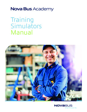
Operation3-3EXT – This setting selects a customer supplied line speed input via theEXT LINE SPEED IN input.Inputs and OutputsThe following analog and digital inputs and outputs are provided.Line Speed Ref OutThe ESRS provides an analog indication of commanded speed afterrounding and acceleration have been applied. The analog outputrange is 0V Vout 10V.The output produces a voltage ranging from 0 to 10 V DC as thecommanded speed varies from stationary to the selected maximum.Within the speed range selected, the output voltage is directlyproportional to speed.In Bi-directional Mode, this output produces 10V DC at maximumspeed for both directions of rotation. The direction of rotation is thendefined by the quadrature pulse phase via the Phase Output.The impedance of this output is approximately 300Ω. Therefore toensure low interface errors, any device connected to this outputshould have an input resistance of greater than 30kΩ.Strobe OutThe Strobe Out is a TTL Digital Output providing a buffered signal totrigger stroboscopes, oscilloscopes, and so forth.This output provides a TTL square wave whose rising edge issynchronized to the rising edge of the Index pulse.Publication 4100-IN505A-EN-P - October 2000
3-4OperationThe Strobe Out is a square wave. Its falling edge is centered betweenthe consecutive rising edges of the Index Pulse.Figure 3.1 ESRS Strobe and Index PulsesExt Line Speed InThis is an analog input requiring a DC voltage within the range of-10V Vin 10V. You can set the commanded speed from an analogvoltage within this range. Within the selected range, the motor speedis directly proportional to input voltage.In Unidirectional mode, zero speed occurs at 0V input voltage andmaximum speed occurs at 10V DC input voltage. The direction ofrotation in this mode is set by the Options switch.In Bi-directional mode, zero speed occurs at 0V DC input voltage.Maximum reverse speed occurs at -10V DC input voltage andmaximum forward speed occurs at 10V DC input voltage.When the ESRS is set to EXT, the LINE SPEED control has no function.The input resistance of this input is 100kΩ. Therefore the outputresistance of the device driving this input should be 1kΩ or less toavoid interface errors.Input clamping at 15V is provided at this input. The input current isnot limited by the ESRS when clamping occurs.Acceleration and rounding are operational in this mode.P1The P1 connector is a 2 part 6 way mating screw that lets you makethe connection to the Enable Voltage Input and Output and theDirection Output.Publication 4100-IN505A-EN-P - October 2000
Operation3-5The following table shows the Pin number and its signal name.Table 3.A P1 Pin FunctionsPin Number123456Signal NameEnable Voltage, 15VEnable Voltage, 0VEnable InputEnable InputDirection InputDirection Output, 0VEnable VoltageThis provides a current limited supply to power the Enable input.Enable InputThis input, which is opto-isolated, allows control of the ESRS via anapplied voltage in the range of 5 to 24V DC. The Enable voltage canbe applied with either polarity (AC voltages cannot be used). Voltagemust be applied to the Enable Input to make the chosen linereference available. Removing the Enable voltage has the same effectas selecting STOP on the SELECTION switch.In situations where it is required to control the ESRS via volt freecontacts, the Enable voltage provided can be routed through these tothe Enable Input.In cases where you supply the Enable voltage, the current required todrive this input can be determined by calculating:IENABLE (VENABLE - 1.5) / 4700Direction OutputThis digital output indicates the phase of the quadrature pulse train.The switched element is a relay with contact rating of 24V DC at 0.5 A.The following table defines the functionality of the Direction Output.Table 3.B Output Direction ValuesDirection OutputONOFFQuad. Pulse PhaseA leads BB leads APublication 4100-IN505A-EN-P - October 2000
3-6OperationP2The P2 connector is a 15 way male high density D connector. It allowsyou to make connection to the quadrature pulse train and index pluspower ( 5 and 12V DC).The following table shows the Pin Number and the matching Signalname.Table 3.C P2 Pin FunctionsPin Number123456789101112131415Signal NameA AB BI (Z )CommonCommon 12V DC 5V DCI- (Z-)Not UsedNot UsedNot Used 5V DCShieldThe A and A-, B and B-, I and I- outputs are RS422 TTL leveloutputs. These outputs are intended to be connected to bi-directionalline receivers in the target equipment. If single ended outputs arerequired A , B , and I outputs can be used and A-, B-, and I- are leftunconnected.Options SwitchPublication 4100-IN505A-EN-P - October 2
EMC Directive This product is tested to meet the Council Directive 89/336/EC Electromagnetic Compatibility (EMC) by applying the following . ESRS Description The Encoder Signal Reference Simulator (ESRS) generates a digital speed reference for a motor and encoder feedback combination. In . Installation.