Transcription
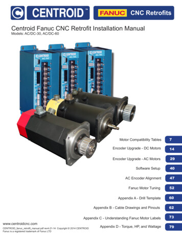
CNC RetrofitsCentroid Fanuc CNC Retrofit Installation ManualModels: AC/DC-30, AC/DC-60Motor Compatibility Tables7Encoder Upgrade - DC Motors14Encoder Upgrade - AC Motors29Software Setup40AC Encoder Alignment47Fanuc Motor Tuning52Appendix A - Drill Template60Appendix B - Cable Drawings and Pinouts62Appendix C - Understanding Fanuc Motor Labels73Appendix D - Torque, HP, and Wattage79www.centroidcnc.comCENTROID fanuc retrofit manual.pdf rev4-21-14 Copyright 2014 CENTROIDFanuc is a registered trademark of Fanuc LTD
Fanuc RetrofitsREAD YOUR CNC11 OPERATORS MANUAL AND AC/DC USERS GUIDE BEFORE PERFORMING A FANUC RETROFIT.FAILURE TO FOLLOW THE INSTRUCTIONS AND SAFETY PRECAUSTIONS IN THOSE MANUALS COULD RESULT INSERIOUS INJURY OR DEATH.DRIVE WARRANTY DOES NOT COVER DAMAGE BY FAULTY MOTORS OR WIRING.The information provided by CENTROID relating to wiring, installation, and operation of CNC components is intended onlyas a guide, and in all cases a qualified technician and all applicable local codes and laws must be consulted. CENTROID makesno claims about the completeness or accuracy of the information provided, as it may apply to an infinite number of field conditions.As CNC control products from CENTROID can be installed on a wide variety of machine tools NOT sold or support byCENTROID, you MUST consult and follow all safety instructions provided by your machine tool manufacture regardingthe safe operation of your machine and unique application.The procedures detailed in this manual are designed to be used by someone familiar with the AC/DC drive and MPU11software. This documentation is designed to be used in correlation with the available manuals and technical bulletins, and is notintended to replace any pre-existing documentation.Only Fanuc motor handling safety procedures are described in this procedure. Additional safety information can be foundin the CNC 11 Operators Manual and the AC/DC Users guide.Servo Motor HandlingWhen working with servo motors: NEVER pick up or carry the motor by the cables or the shaft. (Always carry by the frame.) Use a crane or lift tomove the motor when necessary. NEVER drop or subject the motor to impact. The servo motor is a precision device. NEVER set heavy or sharp objects on the motor or cables. Do not step or sit on the motor or cables. NEVER use a metal hammer on any part of the motor. If it is absolutely necessary to use a hammer, use a plastichammer.Keep the motor properly secured and away from the edge of the work area when servicing the motor, as a dropped motor couldcause personal injury or destroy the motor.Page 2 of 80
Fanuc RetrofitsComplete the Following Checklist BEFORE powering on your drive.Failure to do so could void your warranty.To be performed with motors disconnected from drive: Check for 100 MΩ between the motor chassis and motor power terminals.To be performed with motors connected to drive: Confirm continuity between the drive chassis and the motor chassis. On the drive terminals, check for 100 MΩ between motor shield and power terminals. Check VM wiring for correct polarity. Check motor wiring for correct polarity/phase. Check that all screws are tightened down properly.Driving a motor with a terminal loosenedcould result in the terminal block overheating and causing a fire. If you are unsure of the condition of a motor, have it inspected by a qualified professional.Refer to TB155 for further details.Page 3 of 80
Fanuc RetrofitsBasic Motor Safety, Procedures, and Best Practices Be safely dressed when handling a motor. Wear safety shoes and gloves. Avoid loose clothing which can get caughton the motor. Be careful not to let hair get caught in the rotary section of the motor. Do not handle the motor with wet hands. Shut off the power before working on a motor. Wait at least 5 minutes after the motor is shut off before touching anypower terminals. Always use the correct cables. Centroid cables are shown in the motor compatibility table. Wiring diagrams and pin outsfor motors are provided in Appendix B. Ensure that the motor and motor related components are mounted securely. Ensure that the base or frame to which themotor is mounted to is strong enough. Do not touch the rotary section of the motor when it is running unless instructed to. When attaching a component having inertia to the motor, ensure any imbalance between the motor and component isminimized. Be sure to attach a key to a motor with a keyed shaft. Use the motor in appropriate environmental conditions. Do not store flammables in close proximity to the motor. Whennot in use, store the motor in a dry location between 0 to 40 C. Do not remove the nameplate from a motor.Page 4 of 80
Fanuc RetrofitsTable of ContentsGetting StartedIntroduction. 7Motor Compatibility TablesAC Motors. 8DC Motors. 10Spindles Motors. 12Encoder Upgrade Kit InstallationDC MotorsBlack End Cap (Fanuc Gettys) with Tachogenerator.15DC Motors with Stock Encoders.22AC motorsEarly red cap and S Series. 30α and αC Series. 31Software SetupSoftware SetupControl Configuration. 41Motor Parameters. 42Temperature Coefficients. 43PID and Motor Setup. 44AC Encoder AlignmentIntroduction. 48Procedure. 49Tuning the Fanuc Motor on a AC/DCMaximum Feed Rate. 53Introduction to PID. 54PID Tuning Setup. 55Acceleration Tuning. 56Inertia Tuning. 57Position Kp Tuning. 58Position Kd Tuning. 59Performing a System Test. 60AppendicesAppendix A - Drill Template. 61Appendix B - Cable Drawings and PinoutsCentroid Encoder Cable. 63Fanuc Encoder Cable. 64QD200 Pigtail for Black Cap Motors. 65QR12 Pigtail for AC Motors.66QD200 Pigtail for Yellow Cap Motors.67Extra Large AC Power Cable. 68Large AC Power Cable. 69Large DC Power Cable. 70Medium AC/DC Power Cable.71Motor Pinouts. 72Appendix C - Understanding Fanuc Motor LabelsBlack Caps. 74Yellow Caps. 75AC Motors. 76Spindle Motors. 78Appendix D - Torque, HP, and WattageDC Motors. 80AC Motors. 81Page 5 of 80
Fanuc RetrofitsIntroductionWith the large number of aging FANUC equipped CNC machine tools in the world, CENTROID has answered the call foran affordable and reliable upgrade! Directly control FANUC servo motors with CENTROID's MPU11 based AC/DC drive.Retaining the Fanuc servo motor while eliminating the Fanuc user interface and motion control provides savings in time andmoney.This manual covers: How to install, align, configure, and tune Fanuc AC and DC motors using Centroid encoders. How configure and tune DC Fanuc motors re-using original Fanuc pulse coders The basics needed to connect a Fanuc spindle motor to a GPIO4DMotor series supported: Gettys Fanuc (Black Cap) M Series (Yellow Cap) Early red caps S Series α SeriesαC Seriesβ SeriesThree models of spindle servo motors.If the Fanuc motor has a yellow or black end cap, it is a DC motor. If the Fanuc motor has a red cap, it is an AC motor.The first step in retrofitting a motor to find your motor in our Motor Compatibility Tables listed on the following pages. Samples ofFanuc motor labels are shown in Appendix to help identify your motor.Page 6 of 80
Fanuc RetrofitsFanuc AC Motor Compatibility Table [1]Fanuc MotorSeriesMotorModelMotor TypePowerCable[4]AC/DCDriveModelEncoderRetrofit KitEncoderCable0A06B-0511-BxxxMedium AC or DC CableRetrofit Kit # 12859Drawing #. 6B-0501-BxxxEarly Red CapsInstructionsLarge AC Power Cable20A06B-0502-BxxxPage 31Drawing # S13362AC/DC - xxx5SA06B-0314-BxxxMedium AC or DC CableDrawing # S133705S/3000A06B-0514-BxxxAC/DC – 30[2]6SA06B-0316-BxxxRetrofit Kit # 128596S/3000A06B-0320-Bxxxor # 1287610SA06B-0315-Bxxx10S/3000 A06B-0317-BxxxSee next page toLarge AC Power Cable20SA06B-0502-Bxxxchoose a kit for yourSub assembly # 12894S Series20S/1500application.Drawing # S13362A06B-0505-Bxxx20M[7]AC/DC - 6030SA06B-0590-Bxxx30RExtra Large AC Power CableA06B-0506-BxxxDrawing # S1337130/200040A06B-0581-Bxxx20S/3000 A06B-0318-Bxxx30S/3000 A06B-0319-BxxxNot Recommended [3]40S/2000 A06B-0583-Bxxxα3/3000A06B-0123-BxxxMedium AC or DC Cableα6/2000A06B-0127-BxxxDrawing # S13370α6/3000A06B-0128-BxxxAC/DC – 30[2]αC12/2000 A06B-0141-BxxxAC/DC Encoder Cableα12/2000 A06B-0142-BxxxRetrofit Kit # 12876 Sub assembly #12912α12/3000 A06B-0143-BxxxDrawing # S13369Large AC Power CableαC22/1500 A06B-0145-BxxxInstallationSub assembly # 12894α22/1500 A06B-0145-BxxxInstructionsDrawing # S13362α (Alpha) Seriesα22/1500 A06B-0146-BxxxPage 28α30/1200 A06B-0151-BxxxAC/DC - 60α22/2000 A06B-0147-Bxxx&α30/2000 A06B-0152-BxxxExtra Large AC Power CableA06B-0157-BxxxDrawing # S13371α40/2000(Without fan)αC Series[6]αC3/2000 A06B-0121-BxxxαC6/2000 A06B-0126-Bxxxα22/3000 A06B-0148-Bxxxα30/3000 A06B-0153-BxxxA06B-0158-BxxxNot Recommended [3]α40/2000(With 2/3000A06B-0373-Bxxxβ3/3000 A06B-0033-Bxxxβ6/2000 A06B-0034-Bxxxβ (Beta) SeriesTBD[5]β4/4000is A06B-0063-Bx0xPlease contact Centroid for a retrofit solution.β8/3000is A06B-0075-B203β12/300is A06B-0078-Bx0x&β22/2000is A06B-0085-Bx0xβ0.5/3000 A06B-0113-Bxxxβis Seriesβ1/3000 A06B-0031-BxxxNot Recommended [3]β2/3000 A06B-0032-Bxxx1. This table is not a complete list of all Fanuc AC motors, just motors we have verified.2. An AC/DC-60 may be substituted for an AC/DC-30.3. Motors with a continuous stall current of above 30A or below 5A are not recommended with the AC/DC. (This gives the AC/DC an approximate range of 500watts to 6,000 watts or 0.7 hp to 7.8 hp.)4. You may reuse the existing power cables from your Fanuc with the AC/DC. Cable information is provided for ordering replacement cables and troubleshooting.5. Encoder retrofit kit currently not available, Centroid can provide engineering to develop or installer to mount encoder.6. Most Fanuc documentation lists the αC Series as a member of the α Series, while some Fanuc documentation lists the αC Series as a member of the β series.7. Not to be confused with the yellow-capped DC motor also designated "20M".Cable drawings and pinouts can be found in Appendix B, Motor RPM, torque, hp, and wattage can be found in Appendix DPage 7 of 80
Fanuc RetrofitsChoosing a Retrofit Kit for Your Fanuc “S” Series AC Servo MotorIn order to differentiate between the two different styles of encoder used on Fanuc's “S” series motors, it is necessary toremove the red motor end caps and visually inspect the pulse coders.If your servo motor's encoder resembles this one, you will need assembly #12859. Instructions found in section “ACMotors: Early and S Series Models” on page 31.If your servo motor's encoder resembles this one, you will need assembly #12876. Instructions found in section “ACMotors: α (Alpha) Series Models” on page 37.Page 8 of 80
Fanuc RetrofitsBlack End Cap (Fanuc Gettys)DC Motor Compatibility Table 0613-B0xxTachogenerator5A06B-0614-Bxxxwhere xxx is 001 - rementTechnologyPulse Coderwhere xxx is 031 or 032PowerCable[3]AC/DCDriveModelEncoderRetrofit KitEncoderCableTBD[4]Medium AC or DC CableDrawing # S13370Large DC Power CableSub assembly # 12895Drawing # S13361AC/DC – 30[2]AC/DC - 60Encoder RetrofitKit # 12903Installation InstructionsPage 15AC/DC Encoder CableSub assembly #12912Drawing #S13369TBD[4]Medium AC or DC CableDrawing # S13370Large DC Power CableSub assembly # 12895Drawing # S13361AC/DC – 30[2]AC/DC - 60Reuse stock Fanucencoder OR replacewith Centroid EncoderRetrofitKit # 12896Fanuc Coder CableSub assembly # 12893Drawing # S13357Installation InstructionsPage 221. This is not a list of all Fanuc DC motors, just the motors we have verified.2. An AC/DC-60 servo drive may be substituted for an AC/DC-30 servo drive.3. You may reuse the existing power cables from your Fanuc with the AC/DC. Cable information is provided for ordering replacement cables and troubleshooting.4. CENTROID Encoder retrofit kit has not been developed yet. Centroid can provide engineering services to develop an encoder kit or adapt your own.Motors with a continuous stall current of above 30A or below 5A are not recommended with the AC/DC servo drive.(This gives the AC/DC servo drive an approximate range of 500 watts to 6,000 watts or 0.7 hp to 7.8 hp.)Cable drawings and pinouts can be found in Appendix BMotor RPM, torque, hp, and wattage can be found in Appendix DPage 9 of 80
Fanuc RetrofitsYellow End Cap (M Series)DC Motor Compatibility Table -Bxxx30MA06B-6053-Bxxx0MA06B-0641-Bxxxwhere xxx is 001 or 005Pulse Coderwhere xxx is 011, 012, or coderRetrofit KitAC/DC – 30[2]TBD[4]Medium AC or DC CableDrawing # S13370Large DC Power CableSub assembly # 12895Drawing # S13361Large DC Power CableSub assembly # 12895Drawing # S13361Medium AC or DC CableDrawing # S13370Large DC Power CableSub assembly # 12895Drawing # S13361Large DC Power CableSub assembly # 12895Drawing # S13361Encoder CableAC/DC Encoder CableSub assembly #12912Drawing # S13369AC/DC – 60Reuse stock FanucAC/DC – 30[2] encoder OR replace withCentroid EncoderRetrofitKit # 12896Installation InstructionsPage 22AC/DC – 60AC/DC Encoder Cable( Use with RetrofitEncoder )Sub assembly #12912Drawing # S13369Fanuc Coder Cable( Use with ExistingEncoder)Sub assembly # 12893Drawing # S133571. This is not a list of all Fanuc DC motors, just the motors we have verified.2. An AC/DC-60 servo drive may be substituted for an AC/DC-30 servo drive.3. You may use the existing power cables from your Fanuc with the AC/DC servo drive . Cable information is provided for ordering replacement cables andtroubleshooting.4. CENTROID Encoder retrofit kit has not been developed yet. Centroid can provide engineering services to develop an encoder kit or adapt your own.Motors with a continuous stall current of above 30A or below 5A are not recommended with the AC/DC servo drive.(This gives the AC/DC servo drive an approximate range of 500 watts to 6,000 watts or 0.7 hp to 7.8 hp.)Cable drawings and pinouts can be found in Appendix BMotor RPM, torque, hp, and wattage can be found in Appendix DPage 10 of 80
Fanuc RetrofitsFanuc Spindle InverterIf your spindle is a 6044, 6055, or 5059 and does NOT use optical fiber inputs, then it is compatible with the CentroidGPIO4D Drive Interface and PLC. Supported spindles require a 0 to 10 VDC input with forward and reverse commands. Millswith the orient function contain an extra circuit board on the spindle control as shown below.Spindle Inverter Compatibility Table [1]Spindle Motor -6064-xxxxα## / #### (Alpha Series)SupportModels Without Fibers SupportedNot Supported1. This is not a list of all Fanuc spindle motors, just the motors we have verified.Spindle Control with the ORIENT function.For more reading on AC spindle inverters, read Tech Bulletin #008 “AC Inverter Spindle Motors” and Tech Bulletin#152 “Inverter Control”.If connecting the spindle encoder output directly to a Centroid system (unnecessary in most situations), a Motrona Si 251Sine/Cosine Inerpolater with Adjustable Multiplication Rate Interface is available from Centroid.The following pages contain I/O information and an example schematic.Page 11 of 80
Fanuc RetrofitsI/O Information for a Fanuc Spindle DriveSpindle Drive InputsCN1-21 TLMH (Torque Limit High Gear)Spindle Drive OutputsCN1-5 TLML (Torque Limit Low Gear)CN1-1CN1-6 CommonCN1-2CN1-7 ReadyCN1-3CN1-8 CommonCN1-4CN1-17 High Gear (Used If ORIENT)CN1-24 Low Gear (Used If ORIENT)CN1-18 CommonSpeed Arriv alStoppedCN1-9CN1-10Spindle Speed0 V - 10 V SignalCN1-31CommonCN1-32* The D/A chip on the board needspulled out. It w ill be in a socket on thespindle control board labeled CBI orCCD. Only one socket w ill hav e achip.Torque LimitCN1-11CN1-12AlarmCN1-19 Alarm ResetCN1-15CN1-20 CommonCN1-16Speed DetectCN1-25 OrientCN1-22CN1-26 CommonCN1-23CN1-45 ForwardORIENT CompleteCN1-50 Speed MeterCN1-46 Rev erseCN1-14 CommonCN1- 47 E-StopCN1-49 Load MeterCN1-18 CommonCN1- 48 CommonIf the spindle driv e has the ORIENT function, it w ill hav e a ORIENT card on top of the main card.A20B-0008-0240 (0241)A20B-0008-0030 (0031)A20B-0009-0520CN2 connector has feedback from motor, and MUST be left on.Page 12 of 80
Fanuc RetrofitsExample of a Schematic for a Fanuc Spindle DrivePage 13 of 80
Fanuc RetrofitsDC MotorsYellow (M Series) and Black (Fanuc Gettys) end caps are used on DC motors. At the time of this publication, black capmotors with resolvers and yellow cap motors with tachogenerators/resolvers are not supported.If the motor has a functioning encoder, it can be used without any modification. Skip to Software Setup section.DC Motors: Black End Cap Tachogenerator This guide is for upgrading the tachogenerator on a black end cap motor. To retrofit a black end cap DC motor, use theFanuc Encoder Retrofit Kit 12903 as shown below.Waiting on a new picture!1. 1 Encoder (PN 7546)2. 1 Pigtail Gasket (PN 4602)3. 1 Encoder Drill Template (PN 12906)4. 2 Encoder Mounting Bolts (PN 7485)5. 2 Encoder Mounting Nuts (PN 7571)6. 1 Encoder Pigtail (PN 12890)Page 14 of 80
Fanuc RetrofitsEncoder Installation12Remove the two bolts holding the black end cap in place using a3mm hex key. Set aside the end cap bolts. You will use themagain in a later step.3Remove the end cap to expose the tachogenerator assembly.4Remove the mounting plate bolts using a 3mm hex key. Pull offthe mounting plate. Set aside both the mounting plate andmounting plate bolts, you will use them again in a later step.Disconnect the temperature sensor wires and thetachogenerator wires. Cut the wires to the tachogenerator.Unscrew the wire nuts to remove the wire for the temperaturesensor. DO NOT CUT THE POWER WIRES GOING TO THEMOTOR!Page 15 of 80.
Fanuc Retrofits56Remove the center bolt using a 5mm hex key.7Remove the rotor of the stator of the tachogenerator.Remove the retaining screws on the outer stator with a Phillipsscrewdriver.8Remove the retaining screws on the inner stator with a screwdriver.Page 16 of 80.
Fanuc Retrofits910Remove the remaining piece of the tachogenerator. The motorshould look like this.11Remove the four encoder connector screws. Set aside theconnector screws. You will use them again in a later step.12Acquire the mounting plate you removed in Step 3. If themounting plate is dirty or greasy, clean it with some isopropylalcohol. Cut out the 1-inch hole on the center of the sticker andapply to the mounting plate. If your sticker gets lost or damaged,a template to make a new one is included in Appendix A.Use a center punch to mark the holes on the mounting plate.Page 17 of 80.
Fanuc Retrofits1413Place the encoder on the mounting plate. Insert the encodermounting bolts through the mounting plate.Use a drill press and a #30 drill bit to make both holes inthe mounting plate.1516Loosely mount the encoder using the nuts included in the retrofit Check to make sure the encoder collar screws are backed out.kit. The bolts should be loose enough that the encoder canSlide the encoder assembly onto the back of the motor.slide slightly in each direction.Page 18 of 80.
Fanuc Retrofits1718Re-insert the mounting plate bolts that were removed in step 3with a 3mm hex key.19Tighten the encoder set screws and mounting bolts.20Slide the gasket with the encoder pigtail into the black end cap. Tighten the encoder pigtail using the bolts you removed in Step10.Page 19 of 80.
Fanuc Retrofits2122Connect the encoder pigtail connector to the encoder.Apply a bead of non-corrosive RTV sealant (such as DowCorning 3165 or 748) onto the end cap mounting surface.Reinstall the end cap with the bolts removed in step 1.You are done installing the encoder!Jump to the Software Setup section.Page 20 of 80.
Fanuc RetrofitsDC MotorsDC Motors: Black and Yellow End Cap with Stock EncoderThis guide is for upgrading the relatively low-resolution Fanuc pulse to a high-resolution encoder. To retrofit a black endcap DC motor, use the Fanuc Encoder Retrofit Kit 12896 as shown below.Waiting on a new picture!1.2.3.1 Encoder and MS Connector (PN 12892)1 Encoder Drill Template (PN 12983)2 Encoder Standoffs (PN 3636)4.5.Page 21 of 80.2 Encoder Mounting Screws (PN 887)1 Pigtail Gasket (PN 4602)
Fanuc RetrofitsEncoder Installation12Remove the two bolts holding the black end cap in placeusing a 3mm hex key. Set aside the end cap bolts. You willuse them again in a later step.Remove the end cap to expose the pulse coder assembly.34Cut the pulse coder signal cable as well as the two temperaturesensor wires. DO NOT CUT THE GROUND WIRE!Using a Phillips screwdriver, remove the three pulse codermounting screws. Set them aside. They will be used again instep 21.Page 22 of 80.
Fanuc Retrofits56Remove the pulse coder. A brass coupling will remain on either Remove and inspect the coupler. It should fit snugly into thethe motor or pulse coder side.encoder and the motor. If the coupler is worn or damaged, ordera new one from Fanuc.Size 0 and 5 motors: Part# A290-0611-x532Size 10, 20, 30 motors: Part# A290-0501-x50378Using a hex key, remove the two encoder cover bolts.Remove the encoder cover.Page 23 of 80.
Fanuc Retrofits910Remove all the electronics and optics found within theencoder. Be careful, as the encoder contains a glass diskwhich may shatter during removal. Clean off all dirt and glueresidue.Cut out the center circle on the template, peel off the backing,and apply it to the encoder base. If you wish, you may also cutalong the outer circle on the template and use it as anadditional reference when aligning it. Position the templatesuch that the 6-32 hole locations will not interfere with any ofthe existing holes on the encoder base. The template MUSTBE CENTERED on the encoder base. Improper alignmentcould cause unstable operation as well as cause damage toyour equipment.1112Using a sprung center punch, mark the two hole centers onthe base through the template.Refer to drawing D00327 in appendix A of this manual anddouble check the center mark locations against the drawing.Again, THE HOLE LOCATIONS ARE CRITICAL. Ensure thatthe actual locations of the center marks are within 0.005” fromtheir specified locations.Page 24 of 80.
Fanuc Retrofits1314Using a drill press with a #35 (or 7/64”) drill bit, drill holes onthe center marks approx 0.5” deep. The exact hole depth willvary depending on the clearance required for your tap. Onceagain, check the hole locations against drawing D00327.15Using a 6-32 tap, a tap handle, and some cutting fluid, carefullythread the holes you just drilled to a minimum depth of 0.3”Clean the holes of burrs and shavings.16Using a nut driver, screw the standoffs from your kit into theholes you just tapped. Tighten to approximately 8 In-Lb or 0.9Nm. Do not over-tighten.Page 25 of 80.Slide the encoder onto the shaft.
Fanuc Retrofits1718Using a Phillips screw driver and the crews from the retrofitkit, secure the encoder flex mount to the standoffs. Tighten toapproximately 8 In-Lb or 0.9 Nm.19Using a hex key, tighten the two set screws on the encodercollar.20Re-insert the brass coupler removed in step 6.Line up the coupling and place the encoder base back into itsoriginal location on the motor.Page 26 of 80.
Fanuc Retrofits2118Re-insert the screws that were removed in step 4. If theground wire was originally held down by one of the mountingscrews, re-attach it now. Alternately, the ground wire may bebolted to one of the unused holes in the motor chassis with am4 bolt or screw.19Using a Phillips screw driver, remove the four MS connectormounting screws. Set them aside. They will be used again instep 24.20Remove the original MS connector, wiring, and gasket. Cleanthe mounting area.Install the pigtail connector and gasket from your kit using thescrews removed in step 22.Page 27 of 80.
Fanuc Retrofits2122Connect the pigtail to the encoder.Apply a bead of non-corrosive RTV sealant (such as DowCorning 3165 or 748) onto the end cap mounting surface.Reinstall the end cap with the bolts removed in step 1.You are done installing the encoder!Jump to the Software Setup section.Page 28 of 80.
Fanuc RetrofitsAC MotorsRed end caps are used on Fanuc AC motors. The Fanuc AC motors have coders/encoders that use a physically differentconnector and a proprietary continuation protocol and must be retrofitted
Centroid Fanuc CNC Retrofit Installation Manual Models: AC/DC-30, AC/DC-60 7 14 29 40 47 52 60 62 73 www.centroidcnc.com CNC Retrofits Motor Compatibility Tables Encoder Upgrade - DC Motors Encoder Upgrade - AC Motors Software Setup AC Encoder Alignment Fanuc Motor Tuning Appendix A
