Transcription
Encoders forServo Drives11/2017
BrochureRotary EncodersThis brochure is not intended as anoverview of the HEIDENHAIN productprogram. Rather it presents a selection ofencoders for use on servo drives.ProduktübersichtDrehgeberIn the selection tables you will find anoverview of all HEIDENHAIN encoders foruse on electric drives and the mostimportant specifications. The descriptionsof the technical features containfundamental information on the use ofrotary, angular, and linear encoders onelectric drives.The mounting information and thedetailed specifications refer to the rotaryencoders developed specifically for drivetechnology. You will find more encoders inthe corresponding product documents.Product OverviewRotary Encoders forthe Elevator IndustryDrehgeber für dieAufzugsindustrieJuni 2017Oktober 2016BrochureAngle EncodersWith Integral BearingProduct OverviewRotary Encoders forPotentially ätemit EigenlagerungDrehgeberfür explosionsgefährdeteBereiche (ATEX)April 2016März 2015BrochureModular AngleEncodersWith Optical ScanningFor more information:For the linear and angular encodersalso listed in the selection tables, youwill find more detailed information, suchas mounting information, specificationsand dimensions in the respectiveproduct documents.ModulareWinkelmessgerätemit optischerAbtastungBrochureModular AngleEncodersWith Magnetic ScanningModulareWinkelmessgerätemit magnetischerAbtastung09/2017Oktober 2015BrochureLinear EncodersFor NumericallyControlled Machine ToolsLängenmessgerätefür gesteuerteWerkzeugmaschinenJuni 2017For more information:Comprehensive descriptions of allavailable interfaces as well as generalelectrical information are included in theInterfaces of HEIDENHAIN Encodersbrochure.BrochureExposed LinearEncodersOffeneLängenmessgeräteApril 2016This brochure supersedes all previouseditions, which thereby become invalid.The basis for ordering from HEIDENHAINis always the brochure edition valid whenthe order is made.Standards (ISO, EN, etc.) apply onlywhere explicitly stated in the brochure.
ContentsOverviewExplanation of the selection tables6Rotary encoders for integration in motors8Rotary encoders for mounting on motors12Rotary encoders and angle encoders for integrated and hollow-shaft motors18Exposed linear encoders for linear drives20Technical features and mounting informationRotary encoders and angle encoders for three-phase AC and DC motors24HMC 626Linear encoders for linear drives28Safety-related position measuring systems30Measuring principles32Measuring accuracy35Mechanical designs, mounting and accessories38General mechanical information48SpecificationsRotary encoders withintegral bearingECN/EQN 1100 series56ERN 102358ERN 112360ECN/EQN 1300 series62ECN/EQN 400 series66ERN 1300 series68EQN/ERN 400 series70ERN 401 series72Rotary encoders without ECI/EQI 1100 seriesintegral bearingECI/EBI 1100 series76ECI/EQI 1300 series78ECI/EBI 100 series82ECI/EBI 4000 series84ERO 1200 series88ERO 1400 series9074Electrical connectionInterfaces92Cables and connecting elements104Interface electronics114Diagnostic and testing equipment116
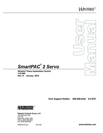
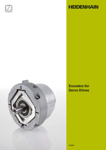
Encoders for servo drivesControlling systems for servo drivesrequire measuring systems that providefeedback for the position and speedcontrollers and for electronic commutation.The properties of encoders have decisiveinfluence on important motor qualitiessuch as: Positioning accuracy Speed stability Bandwidth, which determines drivecommand-signal response anddisturbance rejection capability Power loss Size Noise emission SafetyDigital position and speed controlRotary encoder (actual position value,actual speed value,commutation signal)MiiiCalculation couplingCurrentcontrollerInverterHEIDENHAIN offers the appropriatesolution for any of a wide range ofapplications using both rotary and linearmotors: Absolute and incremental rotaryencoders with and without commutationtracks Absolute and incremental angleencoders Absolute and incremental linearencoders Absolute and incremental modularencodersRotary encoders4
All the HEIDENHAIN encoders shown inthis brochure involve very little cost andeffort for the motor manufacturer to mountand wire. Encoders for rotary motors are ofshort overall length. Some encoders, dueto their special design, can performfunctions otherwise handled by safetydevices such as limit switches.Motor for “digital” drive systems (digital position and speed control)Rotary encoderAngle encodersLinear encoders5
Explanation of the selection tablesThe tables on the following pages list the encoders suited forindividual motor designs. The encoders are available with dimensionsand output signals to fit specific types of motors (DC or AC).Rotary encoders for mounting on motorsRotary encoders for motors with forced ventilation are either builtonto the motor housing or integrated. As a result, they arefrequently exposed to the unfiltered forced-air stream of the motorand must have a high degree of protection, such as IP64 or better.The permissible operating temperature seldom exceeds 100 C.In the selection table you will find: Rotary encoders with mounted stator coupling with highnatural frequency—virtually eliminating any limits on thebandwidth of the drive Rotary encoders for separate shaft couplings, which areparticularly suited for insulated mounting Absolute rotary encoders with purely digital data transfer orcomplementary sinusoidal TTL or HTL incremental signals Incremental rotary encoders with high quality sinusoidaloutput signals for digital speed control Incremental rotary encoders with TTL or HTL compatibleoutput signals Information on rotary encoders that are available as safetyrelated position encoders under the designation functionalsafetyFor selection table see page 12Rotary encoders for integration in motorsFor motors without separate ventilation, the rotary encoder is builtinto the motor housing. This configuration places no stringentrequirements on the encoder for a high degree of protection. Theoperating temperature within the motor housing, however, canreach 100 C and higher.In the selection table you will find: Absolute rotary encoders for operating temperatures up to115 C, incremental rotary encoders for operatingtemperatures up to 120 C Rotary encoders with mounted stator coupling with highnatural frequency—virtually eliminating any limits on thebandwidth of the drive Absolute rotary encoders with purely digital data transfer—suited for the HMC 6 single-cable solutions—or complementarysinusoidal incremental signals Incremental rotary encoders for digital speed control withsinusoidal output signals of high quality—even at highoperating temperatures Incremental rotary encoders with additional commutationsignal for synchronous motors Incremental rotary encoders with TTL-compatible outputsignals Information on rotary encoders that are available as safetyrelated position encoders under the designation functionalsafetyFor selection table see page 86
Rotary encoders, modular encoders and angle encoders forintegrated and hollow-shaft motorsRotary encoders and angle encoders for these motors havehollow through shafts in order to allow supply lines, for example,to be conducted through the motor shaft—and therefore throughthe encoder. Depending on the conditions of the application, theencoders must either feature up to IP66 protection or—for examplewith modular encoders using optical scanning—the machine mustbe designed to protect them from contamination.In the selection table you will find: Encoders with high quality absolute and/or incrementaloutput signals Angle encoders and modular encoders with the measuringstandard on an aluminum or steel drum for shaft speeds up to42 000 rpm Encoders with integral bearing, with stator coupling or modulardesign Encoders with good acceleration performance for a broadbandwidth in the control loopFor selection table see page 18Linear encoders for linear motorsLinear encoders on linear motors supply the actual value both forthe position controller and the velocity controller. They thereforeform the basis for the servo characteristics of a linear drive. Thelinear encoders recommended for this application: Have low position deviation during acceleration in the measuringdirection Have high tolerance to acceleration and vibration in the lateraldirection Are designed for high velocities Provide absolute position information with purely digital datatransmission or high-quality sinusoidal incremental signalsExposed linear encoders are characterized by: Higher accuracy grades Higher traversing speeds Contact-free scanning, i.e., no friction between scanning headand scaleExposed linear encoders are suited for applications in cleanenvironments, for example on measuring machines or productionequipment in the semiconductor industry.For selection table see page 20Sealed linear encoders are characterized by: A high degree of protection Simple installationSealed linear encoders are therefore ideal for applications inenvironments with airborne liquids and particles, such as onmachine tools.For selection table see page 227
Selection guideRotary encoders for integration in motorsProtection: up to IP40 (EN 60 529)SeriesOverall umfrequency ofoperatingstator coupling temperatureVoltage supply 15 000 rpm/ 12 000 rpm–DC 3.6 V to 14 VRotary encoders without integral bearingECI/EQI 1100ECI/EBI 1100110 C115 CECI/EQI 1300 15 000 rpm/ 12 000 rpm–115 CDC 4.75 V to 10 VDC 3.6 V to 14 VECI/EBI 100 6000 rpm–115 CDC 3.6 V to 14 V 6000 rpm–115 CDC 3.6 V to 14 V100 CDC 10 V to 28.8 VD: 30/38/50 mmECI/EBI 4000D: 90/180 mmERO 1200 25 000 rpm–100 CDC 5 V 0.5 VERO 1400 30 000 rpm–70 CDC 5 V 0.5 VDC 5 V 0.25 VDC 5 V 0.5 V1)8Also available with functional safety2)After internal 5/10/20/25-fold interpolation
Signal periodsper revolutionPositions delFurtherinformation–524 288 (19 bits)–/4096EnDat 2.2/22ECI 11191)/EQI 11311)Page 74262 144 (18 bits)–/65 536ECI 1118/EBI 1135Page 76524 288 (19 bits)–/4096ECI 13191)/EQI 13311)Page 78323)–EnDat 2.2/01 with 1 VPPPage 80EnDat 2.2/22–EnDat 2.1/01 with 1 VPPECI 119–/65 5363)EnDat 2.2/22ECI 119/EBI 135–/65 5363)EnDat 2.2/22ECI/EBI 4010–DRIVE-CLiQECI 4090S TTLERO 1225 1 VPPERO 1285 TTLERO 14205000 to 37 5002) TTLERO 1470512/1000/1024 1 VPPERO 148032524 288 (19 bits)––1024/2048512/1000/10243)1 048 576 (20 bits)––Page 82Page 84Page 88Page 90Multiturn function via battery-buffered revolution counter9
SeriesOverall dimensionsMechanicallypermissiblespeedNatural freq.of the statorcouplingMaximumoperatingtemperatureVoltage supplyRotary encoders with integral bearing and mounted stator couplingECN/EQN/ERN 1100ECN/EQN/ERN 1300 12 000 rpm 1000 Hz115 CDC 3.6 V to 14 V 6000 rpm 1600 Hz90 CDC 5 V 0.5 V 15 000 rpm/ 12 000 rpm 1800 Hz115 CDC 3.6 V to 14 V 15 000 rpm(not with ERN)120 CDC 5 V 0.5 VERN 1381/4096:80 CDC 5 V 0.25 VDC 10 V to 28.8 V1)Also available with functional safety10
Signal periodsper revolutionPositions delFurtherInformation5128192 (13 bits)–/4096EnDat 2.2/01 with 1 VPPECN 1113/EQN 1125Page 56–8 388 608 (23 bits)EnDat 2.2/22ECN 11231)/EQN 11351)500 to 81923 block commutation signals TTLERN 1123Page 60512/20488192 (13 bits)EnDat 2.2/01 with 1 VPPECN 1313/EQN 1325Page 62–33 554 432 (25 bits)EnDat 2.2/22ECN 13251)/EQN 13371)1024/2048/4096– TTLERN 1321–/4096ERN 13263 block commutation signals512/2048/4096–2048Z1 track for sine commutation–16 777 216 (24 bits) –/4096Page 68 1 VPPERN 1381ERN 1387DRIVE-CLiQECN 1324 S/EQN 1336 S Page 6411
Rotary encoders for mounting on motorsProtection: up to IP64 (EN 60 529)SeriesOverall dimensionsMechanicallypermissiblespeedNatural freq.of the statorcouplingMaximumoperatingtemperatureVoltage supply100 CDC 3.6 V to 14 VRotary encoders with integral bearing and mounted stator couplingECN/ERN 100D 30 mm: 6000 rpm 1000 HzD 30 mm: 4000 rpmECN/EQN/ERN 400Stator coupling for plane surfaces 6000 rpmUniversal stator couplingWith two shaftclamps (only forhollow throughshaft): 12 000 rpmDC 5 V 0.5 VStator couplingfor planesurfaces: 1500 HzUniversal statorcoupling: 1400 Hz85 CDC 10 V to 30 V100 CDC 3.6 V to 14 VDC 4.75 V to 30 VDC 5 V 0.5 VDC 10 V to 30 V70 CECN/EQN/ERN 400Stator coupling for plane surfaces 6000 rpmWith two shaftclamps (only forhollow throughshaft): 12 000 rpmStator couplingfor planesurfaces: 1500 HzUniversal statorcoupling: 1400 Hz100 CDC 5 V 0.5 V100 CDC 10 V to 30 VDC 4.75 V to 30 VDC 3.6 V to 14 VDC 10 V to 28.8 VECN/EQN/ERN 400Expanding ring coupling 15 000 rpm/ 12 000 rpm 15 000 rpm(not with ERN)83.2Plane-surface coupling50.51)Also available with functional safety1222Expanding ringcoupling: 1800 HzPlane-surfacecoupling: 400 Hz100 CDC 3.6 V to 14 VDC 5 V 0.5 VDC 5 V 0.25 V
Signal periodsper revolutionPositions delFurtherinformation20488192 (13 bits)–EnDat 2.2/01 with 1 VPPECN 113–33 554 432 (25 bits)EnDat 2.2/22ECN 125Brochure:RotaryEncoders1000 to 5000– TTL/ 1 VPPERN 120/ERN 180 HTLERN 130EnDat 2.2/01 1 VPPECN 413/EQN 425512/20488192 (13 bits)–/4096–33 554 432 (25 bits)EnDat 2.2/22ECN 425/EQN 4375128192 (13 bits)SSIECN 413/EQN 425250 to 5000– TTLERN 420 HTLERN 430 TTLERN 460 1 VPPERN 480EnDat H HTLSSI 41H HTLEQN 4251000 to 5000256 to 20488192 (13 bits)–/4096512 to 4096–Brochure:RotaryEncodersEnDat T TTLSSI 41T TTLFanuc05/Fanuc02/Fanuc06ECN 425 F/EQN 437 F33 554 432 (25 bits)/8 388 608 (23 bits)Mit03-4ECN 425 M/EQN 435 M16 777 216 (24 bits)DQ01ECN 424 S/EQN 436 SEnDat 2.2/01 with 1 VPPECN 413/EQN 425 i: 33 554 432(25 bits)409620488192 (13 bits)–/4096–33 554 432 (25 bits)EnDat 2.2/22ECN 4251)/EQN 4371)1024 to 5000– TTLERN 4212048Z1 track for sine commutationPage 66ProductInformationERN 48713
Rotary encoders for mounting on motorsProtection: up to IP64 (EN 60 529)SeriesOverall dimensionsMechanicallypermissiblespeedNatural freq.of the statorcouplingMaximumoperatingtemperatureVoltage supply100 CDC 3.6 V to 14 VRotary encoders with integral bearing and mounted stator couplingECN/EQN/ERN 1000 12 000 rpm 1500 HzDC 4.75 V to 30 VDC 3.6 V to 14 VERN 1023DC 5 V 0.5 V70 CDC 10 V to 30 VDC 5 V 0.25 V 6000 rpm 1600 Hz90 CDC 5 V 0.5 VRotary encoders with integral bearing and torque supports for Siemens drivesEQN/ERN 400 6000 rpm–100 CDC 3.6 V to 14 VDC 10 V to 30 VDC 5 V 0.5 VDC 10 V to 30 VERN 401 6000 rpm–100 CDC 5 V 0.5 VDC 10 V to 30 V1)After internal 5/10/20/25-fold interpolation14
Signal periodsper revolutionPositions delFurtherinformation5128192 (13 bits)–/4096EnDat 2.2/01 with 1 VPPECN 1013/EQN 1025Brochure:RotaryEncodersSSI–8 388 608 (23 bits)EnDat 2.2/22ECN 1023/EQN 1035100 to 3600– TTL/ 1 VPPERN 1020/ERN 1080 HTLsERN 1030 TTLERN 10705000 to 36 0001)500 to 81923 block commutation signals TTLERN 1023Page 5820488192 (13 bits)EnDat 2.1/01 with 1 VPPEQN 425Page 704096SSI10241024– TTLERN 420 HTLERN 430 TTLERN 421 HTLERN 431Page 7215
Rotary encoders for mounting on motorsProtection: up to IP64 (EN 60 529)SeriesOverall umfrequency ofoperatingstator coupling temperatureVoltage supplyRotary encoders with integral bearing for separate shaft couplingROC/ROQ/ROD 400RIC/RIQ 12 000 rpmSynchro flange–100 CDC 3.6 V to 14 VDC 5 VClamping flangeDC 4.75 V to 30 VDC 10 V to 30 VDC 4.75 V to 30 VDC 3.6 V to 14 VDC 10 V to 28.8 VDC 5 V 0.5 VDC 10 V to 30 V70 CROC/ROQ/ROD 1000 12 000 rpm–100 CDC 5 V 0.5 V100 CDC 3.6 V to 14 VDC 4.75 V to 30 VDC 3.6 V to 14 VDC 5 V 0.5 V70 CDC 10 V to 30 VDC 5 V 0.25 V 12 000 rpm–80 CDC 5 V 0.5 VROD 1900 4000 rpm–70 CDC 10 V to 30 V199 15ROD 6001501)2)3)Also available with functional safetyAfter integral 5/10-fold interpolationOnly clamping flange1618160
Signal periodsper revolutionPositions delFurtherinformation512/20488192 (13 bits)–/4096EnDat 2.2/01 with 1 VPPROC 413/ROQ 425–33 554 432 (25 bits)EnDat 2.2/22ROC 4251)/ROQ 4371)Brochure:RotaryEncoders16262 144 (18 bits)EnDat 2.1/01RIC 418/RIQ 4305128192 (13 bits)SSIROC 413/ROQ 425256 to 20488192 (13 bits)EnDat H HTLSSI 41H HTLROQ 4253)–/4096512 to 4096EnDat T TTLSSI 41T TTLFanuc05/Fanuc02/Fanuc06ROC 425 F/ROQ 437 F33 554 432 (25 bits)/8 388 608 (23 bits)Mit03-4ROC 425 M/ROQ 435 M16 777 216 (24 bits)DQ01ROC 424 S/EQN 436 S TTLROD 426/ROD 42050 to 5000 HTLROD 436/ROD 43050 to 10 0002) TTLROD 4661000 to 5000 1 VPPROD 486/ROD 480EnDat 2.2/01 with 1 VPPROC 1013/ROQ 1025–50 to 10 0002)512 i: 33 554 432 (25 bits)–8192 (13 bits)4096––/4096SSI–8 388 608 (23 bits)EnDat 2.2/22ROC 1023/ROQ 1035100 to 3600– TTLROD 1020 1 VPPROD 1080 HTLsROD 1030 TTLROD 1070 TTLROD 620 HTLROD 630 HTL/HTLsROD 19305000 to 36 0002)512 to 5000600 to 2400––Brochure:RotaryEncoders17
Rotary encoders and angle encoders for integrated and hollow-shaftmotorsSeriesOverall ral freq.of the statorcouplingMaximumoperatingtemperatureAngle encoders with integral bearing and integrated stator couplingRCN 2000– 1500 rpm 1000 HzRCN 23xx: 60 CRCN 25xx: 50 CRCN 5000– 1500 rpm 1000 HzRCN 53xx: 60 CRCN 55xx: 50 CRCN 8000D:60 mmand 100 mm 500 rpm 900 Hz50 CModular angle encoders with optical scanningERA 4000Steel scale drumD1: 40 mm to 512 mmD2: 76.75 mm to560.46 mm 10 000 rpm to 1500 rpm–80 CERA 7000For inside diametermountingD: 458.62 mm to1146.10 mm 250 rpm to 220 rpm–80 CERA 8000For outside diametermountingD: 458.11 mm to1145.73 mm 50 rpm to 45 rpm–80 CERM 2200Signal period ofapprox. 200 µmERM 2400Signal period ofapprox. 400 µmD1: 40 mm to 410 mmD2: 75.44 mm to452.64 mm 19 000 rpm to 3000 rpm–100 CERM 2400Signal period ofapprox. 400 µmD1: 40 mm to 100 mmD2: 64.37 mm to128.75 mm 42 000 rpm to 20 000 rpm–100 CERM 2900Signal period ofapprox. 1000 µmD1: 40 mm to 100 mmD2: 58.06 mm to120.96 mm 35 000 rpm/ 16 000 rpmModular encoders with magnetic scanning1)Interfaces for Fanuc and Mitsubishi controls upon request182)Segment solutions upon request
1)Voltage supplySystemaccuracySignal periodsper revolutionPositions perrevolutionInterfaceModelFurtherinformationDC 3.6 V to 14 V 5“ 2.5”16 38467 108 864 (26 bits)268 435 456 (28 bits)EnDat 2.2/02with 1 VPPRCN 2380RCN 2580 5“ 2.5”–67 108 864 (26 bits)268 435 456 (28 bits)EnDat 2.2/22RCN 23103)RCN 25103)Brochure:AngleEncodersWith IntegralBearing 5“ 2.5”16 38467 108 864 (26 bits)268 435 456 (28 bits)EnDat 2.2/02with 1 VPPRCN 5380RCN 5580 5“ 2.5”–67 108 864 (26 bits)268 435 456 (28 bits)EnDat 2.2/22RCN 53103)RCN 55103) 2“ 1”32 768536 870 912 (29 bits)EnDat 2.2/02with 1 VPPRCN 8380RCN 8580 2” 1”–EnDat 2.2 / 22RCN 83103)RCN 85103)–12 000 to 52 000– 1 VPPDC 3.6 V to 14 VDC 3.6 V to 14 VDC 5 V 0.25 V–Full circle2)36 000 to90 000– 1 VPPERA 4280 C Brochure:AngleERA 4480 C EncodersWithoutERA 4880 C IntegralBearingERA 7480 CDC 5 V 0.25 V–Full circle36 000 to90 0002)– 1 VPPERA 8480 CDC 5 V 0.5 V–600 to 3600– TTLERM 2420 1 VPPERM 2280ERM 2480 1 VPPERM 2484DC 5 V 0.5 V6000 to 44 0003000 to 13 000DC 5 V 0.5 V3)–512 to MagneticScanningERM 2984Also available with functional safety19
Exposed linear encoders for linear drivesSeriesOverall dimensionsTraversing speedAccelerationIn measuringdirectionLIP 400 30 m/min 200 m/sLIF 400 72 m/minLIC 2100Absolute linearencoderLIC 4100Absolute linearencoderAccuracy grade2To 0.5 µm 200 m/s2 3 µm 600 m/min 200 m/s2 15 µm 600 m/min 500 m/s2 5 µm1) 5 µmLIDA 400 480 m/min2 200 m/s 5 µm1) 5 µm2LIDA 200 600 m/min 200 m/s 30 µmPP 200Two-coordinateencoder 72 m/min 200 m/s2 2 µm1)After linear error compensation20
Measuring lengthsVoltage supplySignalperiodCutoff frequency Switching–3 dBoutputInterfaceModelFurtherinformation70 mm to 420 mmDC 5 V 0.25 V2 µm 250 kHz– 1 VPPLIP 481Brochure:ExposedLinearEncoders70 mm to 1020 mmDC 5 V 0.25 V4 µm 300 kHzHoming track 1 VPPLimit switchesLIF 481120 mm to 3020 mm DC 3.6 V to 14 V–––EnDat 2.2/22Resolution0.05 µmLIC 2107140 mm to27 040 mm–––EnDat 2.2/22Resolution0.001 µmLIC 4115DC 3.6 V to 14 VLIC 4117140 mm to 6040 mm140 mm to30 040 mmDC 5 V 0.25 V20 µm 400 kHzLimit switches 1 VPPLIDA 485LIDA 487240 mm to 6040 mmUp to 10 000 mmDC 5 V 0.25 V200 µm 50 kHz– 1 VPPLIDA 287Measuring range68 mm x 68 mmDC 5 V 0.25 V4 µm 300 kHz– 1 VPPPP 28121
Sealed linear encoders for linear drivesProtection: IP53 to IP641) (EN 60 529)SeriesOverall dimensionsTraversingspeedAccelerationIn measuringdirectionNaturalfrequency ofcouplingMeasuringlengthsLF 60 m/min 100 m/s2 2000 Hz50 mm to1220 mmLCAbsolute linearencoder 180 m/min 100 m/s2 2000 Hz70 mm to2040 mm3)LF 60 m/min 100 m/s2 2000 Hz140 mm to3040 mmLCAbsolute linearencoder 180 m/min 100 m/s2 2000Hz140 mm to4240 mmLinear encoders with slimline scale housingLinear encoders with full-size scale housing140 mm to3040 mm140 mm to4240 mm140 mm to3040 mmLB1)2)3)4) 100 m/s 780 Hz3240 mm to28 040 mm 120 m/min(180 m/minupon request) 60 m/s2 650 Hz440 mm to30 040 mm(up to72 040 mmupon request)After installation according to mounting instructionsInterfaces for Siemens, Fanuc and Mitsubishi controls upon requestMeasuring lengths from 1340 mm only with spar or clamping elementsAlso available with functional safety222 120 m/min(180 m/minupon request)
AccuracygradeVoltage supplySignal periodCutofffrequency–3 dBResolutionInterface2)ModelFurtherinformation 5 µmDC 5 V 0.25 V4 µm 250 kHz– 1 VPPLF 485 5 µmDC 3.6 V to 14 V––To 0.01 µmEnDat 2.2/22LC edMachineToolsEnDat 2.2/02LC 485 3 µmTo 0.001 µm 5 µm20 µm 150 kHz 3 µmTo 0.01 µmTo 0.05 µm 2 µm; 3 µmDC 5 V 0.25 V4 µm 250 kHz– 1 VPPLF 185 5 µmDC 3.6 V to 14 V––To 0.01 µmEnDat 2.2/22LC 1154)EnDat 2.2/02LC 185EnDat 2.2/22LC 211EnDat 2.2/02with 1 VPPLC 281 1 VPPLB 382 3 µmTo 0.001 µm 5 µm20 µm 150 kHz 3 µm 5 µmTo 5 MachineToolsTo 0.01 µmTo 0.05 µmDC 3.6 V to 14 VDC 5 V 0.25 V––40 µm 250 kHz40 µm 250 kHzTo 0.01 µm–23
Rotary encoders and angle encodersfor three-phase AC and DC motorsGeneral informationSpeed stabilityTo ensure smooth drive performance,an encoder must provide a large numberof measuring steps per revolution. Theencoders in the HEIDENHAIN productprogram are therefore designed to supplythe necessary numbers of measuringsteps per revolution to meet the speedstability requirement.Transmission of measuring signalsTo ensure the best possible dynamicperformance with digitally controlledmotors, the sampling time of the speedcontroller should not exceed approx. 125 µs.The feedback values for the position andspeed controller must therefore beavailable in the controlling system with theleast possible delay.HEIDENHAIN rotary encoders angleencoders featuring integral bearing andstator coupling provide very goodperformance: shaft misalignment withincertain tolerances (see Specifications)does not cause any position error or impairspeed stability.High clock frequencies are needed to fulfillsuch demanding time requirements onposition-value transfer from the encoder tothe controlling system with serial datatransmission (see also Interfaces; AbsolutePosition Values). HEIDENHAIN encodersfor servo drives therefore provide theposition values via the fast, purely serialEnDat 2.2 interface, or transmit additionalincremental signals that are availablewithout delay for use in the subsequentelectronics for speed and position control.At low speeds, the encoder’s positionerror within one signal period affectsspeed stability. In encoders with purelyserial data transmission, the LSB (LeastSignificant Bit) goes into the speed stability(see also Measuring accuracy).For standard drives, manufacturersprimarily use the especially robustHEIDENHAIN ECI/EQI encoders withoutintegral bearing or rotary encoders withTTL or HTL compatible output signals—as well as additional commutation signalsfor permanent-magnet DC drives.For digital speed control on machineswith high requirements for dynamics,a large number of measuring steps isrequired—usually above 500 000 perrevolution. For applications with standarddrives, as with resolvers, approx. 60 000measuring steps per revolution aresufficient.HEIDENHAIN encoders for drives withdigital position and speed control aretherefore equipped with the purely serialEnDat22 interface, or they additionallyprovide sinusoidal incremental signalswith signal periods of 1 VPP (EnDat01).The high internal resolution of the EnDat22encoders permits resolutions up to 19 bits(524 288 measuring steps) in inductivesystems and at least 23 bits (approx.8 million measuring steps) in photoelectricencoders.Thanks to their high signal quality, thesinusoidal incremental signals of theEnDat01 encoders can be highlysubdivided in the subsequent electronics(see Figure 1). Even at shaft speeds of12 000 rpm, the signal arrives at the inputcircuit of the controlling system with afrequency of only approx. 400 kHz (seeFigure 2). 1 VPP incremental signals allowcable lengths up to 150 m (see alsoIncremental signals – 1 VPP).Fig. 1:Signal periods per revolution and the resulting number of measuring steps per revolution as afunction of the subdivision factorMeasuring steps per revolution Subdivision factorSignal periods per revolution 24
HEIDENHAIN absolute encoders for “digital”drives also supply additional sinusoidalincremental signals with the samecharacteristics as those described above.Absolute encoders from HEIDENHAIN usethe EnDat interface (for Encoder Data) forthe serial data transmission of absoluteposition values and other information forautomatic self-configuration, monitoringand diagnosis. (See Absolute positionvalues – EnDat.) This makes it possible touse the same subsequent electronics andcabling technology for all HEIDENHAINencoders.Important encoder specifications can beread from the memory of the EnDatencoder for automatic self-configuration,and motor-specific parameters can be savedin the OEM memory area of the encoder.The usable size of the OEM memory in therotary encoders in the current brochures isat least 1.4 KB ( 704 EnDat words).Most absolute encoders themselvesalready subdivide the sinusoidal scanningsignals by a factor of 4096 or greater. If thetransmission of absolute positions is fastenough (for example, EnDat 2.1 with2 MHz or EnDat 2.2 with 16 MHz clockfrequency), these systems can do withoutincremental signal evaluation.Benefits of this data transmission technologyinclude greater noise immunity of thetransmission path and less expensiveconnectors and cables. Rotary encoderswith EnDat 2.2 interface offer the additionalfeature of being able to evaluate anexternal temperature sensor, located inthe motor coil, for example. The digitizedtemperature values are transmitted as partof the EnDat 2.2 protocol without anadditional line.BandwidthThe attainable gain for the position and speedcontrol loops, and therefore the bandwidthof the drives for command response andcontrol reliability, are sometimes limited bythe rigidity of the coupling between themotor shaft and encoder shaft as well asby the natural frequency of the statorcoupling. HEIDENHAIN therefore offersrotary and angular encoders for high-rigidityshaft coupling.The stator couplings mounted on theencoders have a high natural frequencyof typically 1800 Hz. For the modular andinductive rotary encoders, the stator androtor are firmly screwed to the motorhousing and to the shaft (see alsoMechanical design types and mounting).This mechanical design therefore permitsoptimal rigidity of the coupling.Figure 2:Shaft speed and resulting output frequency as a function of the number ofsignal periods per revolutionOutput frequency in kHz Signal periods per revolutionMotor currentsMotors are sometimes subjected toimpermissible current from the rotor to thestator. This can result in overheating in theencoder bearing and reduce its service life.HEIDENHAIN therefore recommendsencoders without integral bearings or withinsulating bearings (hybrid bearings). Formore information, please contactHEIDENHAIN.Fault exclusion for mechanical couplingHEIDENHAIN encoders designed forfunctional safety can be mounted so thatthe rotor or stator fastening does notaccidentally loosen.SizeA higher permissible operating temperaturepermits a smaller motor size for a specificrated torque. Since the temperature of themotor also affects the temperature of theencoder, HEIDENHAIN offers encoders forpermissible operating temperatures upto 120 C. These encoders make itpossible to design machines with smallermotors.Power loss and noise emissionThe power loss of the motor, theaccompanying heat generation, and theacoustic noise of motor operation areinfluenced by the position error of theencoder within one signal period. For thisreason, rotary encoders with a high signalquality of better than 1 % of the signalperiod are preferred (see also Measuringaccuracy).Bit error rateFor rotary encoders with purely serialinterface for integration in motors,HEIDENHAIN recommends conducting atype test for the bit error rate.When using functionally safe encoderswithout closed metal housings and/or withcable assemblies that do not comply withthe electrical connection directives (seeGeneral electrical information) it is alwaysnecessary to measure the bit error rate in atype test under application conditions.Shaft speed in rpm 25
HMC 6Single-cable solution for servo drivesMotors normally need two separate cables: One cable for the motor encoder One cable
Overview 6 Explanation of the selection tables 8 Rotary encoders for integration in motors 12 Rotary encoders for mounting on motors 18 Rotary encoders and angle encoders for integrated and hollow-shaft motors 20 Exposed linear encoders for linear drives Technical features and mounting information 24 Rotary encoders and angle encoders for three-phase AC and DC motors