Transcription
Manuals User Manuals Simplified.Lumens AVoIP Encoder/Decoder User ManualDecember 4, 2021December 8, 2021Home » Lumens » Lumens AVoIP Encoder/Decoder User ManualContents [ hide1 Lumens AVoIP Encoder/Decoder2 Package Contents3 Product Overview3.1 Product Applications3.2 System Requirements3.3 I/O Functions Introduction3.4 Description of Indicator Display3.5 IR Pin AssignmentConfiguration4 Installation and Connections4.1 Connection Setting5 Start Using5.1 Network Switch Setting5.2 WebGUI Control Methods6 WebGUI Control Menu7 Product Specifications7.1 Technical Specifications7.2 Image Specifications7.3 Audio Specifications7.4 Wire Specifications8 Troubleshooting9 Safety Instructions10 Copyright Information11 Documents / Resources11.1 Related Manuals / Resources
Lumens AVoIP Encoder/DecoderTo download the latest version of Quick Start Guide, multilingual user manual, software, or driver, etc., please visit Lumenshttps://www.MyLumens.com/supportPackage ContentsOIP-D40E EncoderOIP-D40D Decoder
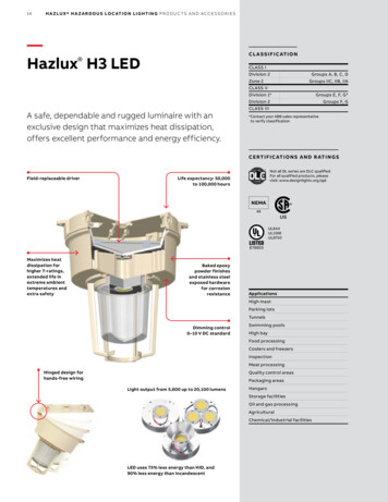
Product OverviewThis product is an HDMI over IP encoder/decoder, which can extend and receive HDMI signals through a Cat.5e network cable underTCP/IP protocol. This product supports HD images (1080p@60Hz) and audio data, and the transmission distance can be 100 meters. If itis equipped with a Gigabit network switch, it can not only extend the transmission distance (up to 100 meters for each connection), butalso receive VoIP signals without loss or delay.In addition to supporting IR and RS-232 bi-directional transmission, this product also supports Multicast of VoIP signals, which can sendthe audio-visual signals of one encoder to multiple decoders in the same area network. In addition, the VoIP signals with multicast canalso be used to build a large video wall composed of multiple displays. This product is perfectly suitable for home use and commercialaudio-visual installation environments, and has a screen display function to quickly check setting information. The control interfaceincludes WebGUI, Telnet and AV over IP controllers.Product ApplicationsHDMI, IR and RS-232 signal extensionMulti-screen broadcast displays in restaurants or conference centersUse connection to long-distance transmit data and imagesMatrix image distribution systemVideo wall image distribution systemSystem RequirementsHDMI audio-visual source devices, such as digital media players, video game consoles, PCs or set-top boxes.A Gigabit network switch supports Jumbo Frame (at least 8K Jumbo Frames).A Gigabit network switch supports Internet Group Management Protocol (IGMP) Snooping. Remark Most consumer-grade routers cannot handle the high traffic flow generated by multicast, so it is not recommended to directlyuse the router as your network switch.It is strongly recommended to avoid mixing your commonly used network traffic with VoIP streaming flow. VoIP streaming flowshould at least use a separate subnet.I/O Functions Introduction2.4.1 OIP-D40E Encoder – Front Panel
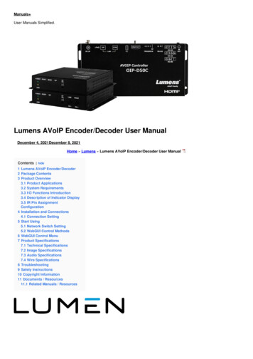
NOItemFunction Descriptions①Power indicatorDisplay the status of the device. Please refer to 2.5 Description of Indicator Display.Connection②③indicatorDisplay the status of connection. Please refer to 2.5 Description of IndicatorDisplay.Reset buttonPress this button to restart the device (all settings will be retained).Press this button to switch image stream to Graphic or Video image processingmodes.④Graphic mode: Optimizing high-resolution static images. Video mode: Optimizing fullmotion images.Image stream button Remark When the device is on, hold down this button to reset the settings. Once thereset is complete, the two indicators will flashquickly. You need to restart the power manually.⑤ISP buttonFor manufacturers only.⑥ISP SEL On/OffFor manufacturers only. The default position of this switch is OFF.OIP-D40E Encoder – Rear Panel
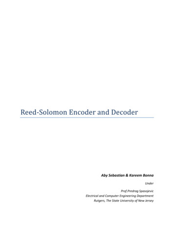
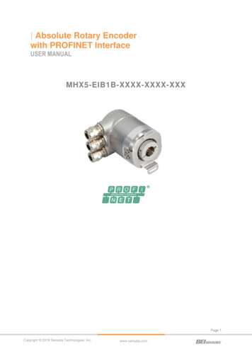
NOItemFunction Descriptions⑦Power portPlug in a 5V DC power supply and connect to an AC outlet.⑧OIP LAN portConnect to a network switch to serially connect compatible decoders and transmit data,while being able to use WebGUI/Telnet control.Connect to a computer, laptop or control equipment to extend the RS-232 signals. Thedefault baud rate is 115200 bps, which can be set by users. Remark With Multicast, the encoder can send RS-232 commands⑨RS-232 portto all decoders, and individual decoders can send RS-232 commands to the encoder.After connecting to IR extender, aim at the remote control to extend the IR controlrange of the remote control to the far ends.⑩IR input port Remark With Multicast, the encoder can send IR signals to all decoders.After connecting to IR emitter, aim at the controlled device to send theIR output portHDMI input portreceived IR signals from the remote control to the controlled device.Connect to HDMI source devices, such as digital media players, video game consoles,or set-top boxes.OIP-D40D Decoder – Front PanelNOItemFunction Descriptions①Power indicatorDisplay the status of the device. Please refer to 2.5 Description of Indicator Display.②Connection indicatorDisplay the status of connection. Please refer to 2.5 Description of Indicator Display.③Reset buttonPress this button to restart the device (all settings will be retained).
④ISP buttonFor manufacturers only.⑤ISP SEL On/OffFor manufacturers only. The default position of this switch is OFF.(1) Channel -: Press this button to switch to the previous availablestreaming channel in the local network. Remark If the device does not detect an available streaming channel, its channelnumber will not be changed.⑥Channel or Link button(2) Image Connection: Press this button for 3 seconds to enable ordisable image connection. When image connection is disabled, the displays connected tothe decoder will show the current IP address andthe firmware version of the system.(1) Channel : Press this button to switch to the next available streamingchannel in the local network. Remark If the device does not detect an available streaming channel, its channelnumber will not be changed.⑦Channel or ImageStream button(2) Image Stream: Press this button to switch image stream to Graphic orVideo image processing modes.Graphic mode: Optimizing high-resolution static images. Video mode: Optimizing fullmotion images. Remark When the device is on, hold down this button to reset thesettings. Once the reset is complete, the two indicators will flash quickly. You need torestart the power manually.OIP-D40D Decoder – Rear Panel
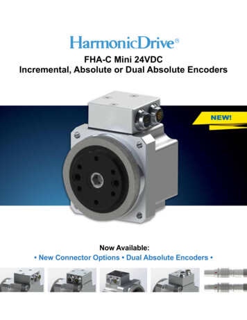
NO⑧ItemFunction DescriptionsHDMI outputConnect to HDMI display or audio-visual amplifier to output digitalportimages and audio.Connect to a computer, laptop or control equipment to extend the⑨RS-232 portNOItemRS-232 signals. The default baud rate is 115200 bps, which can be setFunction Descriptionsby users. Remark With Multicast, the encoder can send RS-232 commands to all decoders, andindividual decoders can send RS-232 commands to the encoder.After connecting to IR extender, aim at the remote control to extend the⑩IR input portIR control range of the remote control to the far ends.After connecting to IR emitter, aim at the controlled device to send the received IRsignals from the remote control to the controlled device. Remark With Multicast, the encoder can send IR signals to allIR output portdecoders.Connect to a network switch to serially connect compatible encoders andOIP LAN porttransmit data, while being able to use WebGUI/Telnet control.Power portPlug in a 5V DC power supply and connect to an AC outlet.Description of Indicator DisplayNameIndicator StatusFlickering: Receiving powerPower indicatorStays On: ReadyOff: No internet connectionFlickering: ConnectingConnection indicatorStays On: Connection is stableIR Pin Assignment Configuration
Serial Port Pin and Default Setting3.5 mm male to D-Sub female adapter cableDefault Setting of the Serial PortBaud Rate115200Data Bit8Parity BitNStop Bit1Flow ControlNInstallation and Connections
Connection Setting1. Use an HDMI cable to connect the video source device to the HDMI input port on the D40E encoder.2. Use an HDMI cable to connect the video display device to the HDMI output port on the D40D decoder.3. Use a network cable to connect the OIP network port of the D40E encoder, D40D decoder, and D50C controller to the networkswitch of the same domain, so that all OIP devices are in the same local area network.4. Plug the transformer into the power ports of D40E encoder, D40D decoder and D50C controller and connect to the power outlet.Steps ①-④ can extend the signal. You can enter the IP address of the encoder or decoder on the browser to control the encoder ordecoder individually. Or use the WebGUI operation interface to control the video display device connected to the D50C controller,which can simultaneously control all encoders and decoders currently connected to the same local network.You can also connect to a computer and IR emitter/receiver. Please refer to the following connection methods:5. Connect a computer, laptop or control device to the RS-232 port to extend the RS-232 signal.6. Connect the IR emitter/receiver to the D40E encoder and D40D decoder to receive IR from the remote control, and use the remotecontrol to control the controlled device.Start UsingVoIP transmission will consume a lot of bandwidth (especially at higher resolutions), and it needs to be paired with a Gigabit networkswitch that supports Jumbo Frame and IGMP Snooping. It is strongly recommended to be equipped with a switch which includes VLAN(Virtual Local Area Network) professional network management.Network Switch SettingNotesMost consumer-grade routers cannot handle the high traffic flow generated by multicast, so it is not recommended to directly use therouter as your network switch. It is strongly recommended to avoid mixing your commonly used network traffic with VoIP streaming flow.VoIP streaming flow should at least use a separate subnet.Setting SuggestionsPlease set Port Frame Size (Jumbo Frame) to 8000.Please set IGMP Snooping and relevant settings (Port, VLAN, Fast Leave, Querier) to [Enable].WebGUI Control MethodsWebGUI control via D40E encoder/D40D decoderThe encoder and decoder have their own WebGUI interface. Open a standard web page browser, enter the IP address of the device, andlog in to the WebGUI interface to connect to the encoder or decoder you’d like to operate. If you don’t know the IP address, temporarilystop the VoIP streaming connection between the encoder and the decoder first. Please press the LINK button on the front panel of thedecoder for 3 seconds (the LINK indicator flickers quickly then is off), and check the IP address on the display connected to the decoder.Once the VoIP streaming is disconnected, the decoder will output a 640 x 480 black screen, and a set of local (equal to the decoder) IPaddress will be shown at the bottom of the screen, and a set of remote (equal to encoder) IP address sharing the same VoIPtransmission channel (the channel number is preset to 0). After obtaining the IP address, please press the LINK button again for 3seconds to restore the original operating state of the device (the LINK indicator lights up first and then stays on).After logging in to the WebGUI interface, you will see a window composed of several tabs. Please click the button at the top of thewindow to check the content of each tab. For each tab and its function, please refer to 5.1 WebGUI Control Menu Descriptions.WebGUI control via theD50C controllerTo activate the WebGUI connection of D50C controller, please open a web page browser, and enter the IP address of the CTRL LANport of D50C controller, or connect the display to the HDMI output port, and connect the keyboard and mouse to the USB port for easyoperation. Whether it is controlled on a web page browser or on a display, all encoders and decoders connected to the same localnetwork can be controlled on the control page at the same time. For the description of the D50C WebGUI control menu, please refer tothe OIP-D50C User Manual.WebGUI Control MenuWebGUI Control Menu DescriptionsThis chapter describes the WebGUI control menu of D40E encoder/D40D decoder. To use the WebGUI control page of D50C controllerto control the device, please refer to OIP-D50C User Manual.System – Version Information
This window will show detailed information about the current firmware version of the device.System – Upgrade the FirmwareDescriptionTo upgrade the firmware of this device, please press [Choose File], select the updated file (*.bin format) from your computer, and thenpress [Upload] to start the update. Remark The update process will take a few minutes to complete, and the device will automatically restart during the process. Whenupdating, the video output may become unsteady.System – Utility Program
NoItemDescriptionTo restore the factory default settings of the device, please press [Factory Default]. If1Commandsyou only need to restart the device (settings will not be reset), please press [Reboot].If the EDID data from the decoder is not compatible with the HDMI signal source, please select thebuilt-in HDMI EDID setting from the encoder (supports 1080p resolution, including audio) to solve thecompatibility problem, and then press [Apply].2Reset EDID toDefault Value Remark If restart the device, the EDID setting will be reset.* The decoder operation interface does not have this function.To send a Telnet command to the device, enter the Telnet command in the Command field, and thenpress [Apply]. The device’s response to the command will be shown on the Output field.3Console APICommandSystem – Statistics Remark To check Telnet commands, please refer toOIP-D40E.D40D TelnetCommand List.
DescriptionThis window will display the current operating status of the device, including host name, network information, MAC address, unicast ormulticast, and connection status and mode.Video Wall – Bezel and Gap CompensationThe video wall page can design, edit and operate a video wall built by displays connected with multiple decoders. In the same video wallsystem, you can choose to control any decoder on any encoder (as long as the channel number is shared), or you can choose to accessthe video wall settings on the encoder and decoder. Some of the changed video wall settings can only be applied to the decoder. Aftersaving the new video wall settings, please set Apply To to select the applied target and then press [Apply]. Remark Although it is feasible to build a small video wall with the unicast mode, it is strongly recommended to give priority to adopt themulticase mode when building a video wall so that the network bandwidth can be used more effectively.DescriptionIt provides the actual size setting of the display of the video wall. Various measurement units (inches, millimeters, centimeters) will do, aslong as all measurements are in the same unit and the numbers are integers. Remark Video walls usually use the same type of displays in the same size. It is also feasible to use displays in different sizes, as longas each display is measured in the same unit. Video wall is laid out in the most common rectangular pattern, and the bezels of eachdisplay are aligned with the center of the video wall.
NoItemDescription1OW(OW) The horizontal size of the display.2OH(OH) The vertical size of the display.3VW(VW) The horizontal size of the signal source screen.4VH(VH) The vertical size of the signal source screen.Set the device which you want to apply the changes to, and then press [Apply]5Apply yoursettingsSelect All, and apply the changes to all encoders and decoders in the current video wall. Select a set of IPaddress on the Clients-end, and apply the changes to the decoder connected to this address.Video Wall – Wall Size and Position LayoutDescriptionProvide the settings regarding the amount of displays in the video wall, and the position of displays. Typical video walls consist of thesame amount of displays in both horizontal and vertical directions (for example: 2 x 2 or 3 x 3). Through this setting, you can build videowalls in various rectangular patterns (for example: 5 x 1 or 2 x 3). Remark The maximum amount of displays for both the horizontal and vertical directions is 16.NoItemDescriptionVertical Monitor1AmountSet the amount of displays in the vertical direction of the video wall (up to 16).Horizontal Monitor2AmountSet the amount of displays in the horizontal direction of the video wall (up to 16).Set the vertical position of the displays currently under control (from top to bottom,3Row Positionranging from 0 to 15).Set the horizontal position of the displays currently under control (from left to right,4Column PositionVideo Wall – Preferenceranging from 0 to 15).
NoItemDescriptionSet the stretch out mode of the screen.– Fit In mode: The original aspect ratio of the image signal will be ignored, and the aspect will bestretched to fit the size of the video wall.1Stretch Out– Stretch Out mode: The original aspect ratio of the image signal will be maintained, and the screenwill be zoomed in/out until it stretches for the four sides of the videowall.2Clockwise RotationSet the rotation degree of the screen, which can be 0 , 180 , or 270 .3Apply your settingsSet the device which you want to apply the changes to, and then press [Apply] Select a set of IPaddress on the Clients-end, and apply the changes to the decoder connected to this address.Show OSD (On4Screen Display)Enable or disable the OSD of the currently selected channel.NetworkDescriptionSet the network control. After changing any settings, please press [Apply] and follow the instructions to restart the device. Remark If the IP address is changed, the IP address used to log in WebGUI must also be changed. If a new IP address is assignedthrough Auto IP or DHCP, stop the image connection between the encoder and the decoder toview the new IP address on the display connected to the decoder.NoItemDescription
Select the broadcast channel of this device from the drop-down menu. As long as the decoder channel is thesame as the encoder in the same local area network, the encoder signal can be received. There are a total of0 to 255 channel numbers.1Channel Setting Remark Encoders in the same local area network must have different channel numbersto avoid conflicts with each other.Select the IP mode and configuration of the device, and quickly search for the device.– Auto IP mode: Automatically assign a set of APIPA address (169.254.XXX.XXX) to itself.– DHCP mode: Automatically obtain a set of address from the DHCP server.2IP Address Setting– Static mode: Manually set the IP address, subnet mask, and default gateway. Press [Apply] to save thenew settings. Remark The pre-set internet is Auto IP mode.After pressing [Show Me], the indicators on the front panel of the device will flash immediately for quick noticeof the device.3Search YourDeviceAfter pressing [Hide Me], the indicators will back to normal.It is very helpful for troubleshooting when a large number of devices are installed in the cabinet.Click the button to select broadcast mode, and press [Apply] to save the new settings. Remark The broadcast mode of the decoder must be the same as that of the encoder to receive the signal.4BroadcastingMode– Multicast: Transfer the image stream of the encoder to multiple decoders at the same time withoutincreasing the bandwidth consumption. This mode is suitable for video wall or matrix audio-visual distribution.It must be paired with a network switch that supports IGMP Snooping.– Unicast: Transfer the image stream of the encoder to each decoder individually, so the bandwidthconsumption will be quite heavy. This mode is suitable for establishing simple peer-to-peer streaming, anddoes not necessarily need to be paired with a network switchthat supports IGMP Snooping.5RestartPress this button to restart the device.Functions – Image Extension/Serial over IP (Encoder)
Image extension over IPNoItemDescriptionSet the maximum bit rate of the image stream. There are five options: Unlimited, 400 Mbps, 200 Mbps,100 Mbps, and 50 Mbps.Selecting Unlimited will use the maximum bit rate of the bandwidth to keep the update frequency of theimage stream intact.1Maximum Bit Rate Remark It is recommended to select Unlimited to transfer 1080p image streams. Bandwidthrequirements will become very large, and the amount of image streams willbe limited.Setting the encoding percentage of the image source (2%-100%) can effectively reduce the bandwidthrequirement of high-resolution images. It is suitable for Power Point presentations or digital signagedisplays, but not suitable for dynamic image displays. Remark If the frame rate of the dynamic images is too low, the frame will beMaximum Frame Rate2intermittent.Serial Extension over IPNoItemDescriptionManually set the baud rate, data bits, parity, and stop bits you need to extend RS-232 signals.3Serial communicationsettings Remark The serial communication settings of the encoder and decoder must be thesame.4RestartPress this button to restart the device.Functions – Image Signals extension/Serial Data over IP (Decoder)
Image extension over IPItemDescriptionEnable imageUncheck to disable image signal extension over IP. Unless troubleshooting is inextension over IPprogress, please check this checkbox.After checking this checkbox with multicast, the EDID data of the device will be sent to the connectedencoder.2Copy EDID data Remark This function can only be used in multicast mode.Select the waiting time when the signal source is lost from the drop-down menu, and a Link Lostmessage will appear on the screen. There are seven options: 3 seconds, 5 seconds, 10 seconds, 20seconds, 30 seconds, 60 seconds, or Never Timeout.3Reminder fordisconnection timeoutIf you check and select Turn off screen, the device will stop sending any signal fromthe HDMI output port after the waiting time expires.Select the output resolution from the drop-down menu.Select one, and the output resolution will become the one you selected.4Scaler output modeImage channel lock(CH /-) for5Select Pass-Through, the output resolution will be the signal source resolution. Select Native, theoutput resolution will be up-converted to the connected display resolution.After pressing [Lock], the image channel selection button will be locked and cannot be used.device buttonSerial Extension over IPNoItemDescriptionUncheck to disable serial extension over IP. Unless you don’t use serial support, please check thischeckbox. Disabling this function can save small amount of bandwidth.Manually set the baud rate, data bits, parity, and stop bits you need to extend RS-232 signals.67Serial communicationsettings Remark The serial communication settings of the encoder and decoder must be thesame.RestartPress this button to restart the device.
Product SpecificationsTechnical SpecificationsDescription of SpecificationsItemD40E EncoderHDMI Bandwidth225 MHz/6.75 GbpsD40D DecoderAudio-visualinput port1x HDMI terminal1x RJ-45 LAN terminalAudio-visual outputport1x RJ-45 LAN terminal1x HDMI terminal1x IR extender [3.5 mm terminal] 1x IRemitter [3.5 mm terminal]1x IR extender [3.5 mm terminal] 1x IRemitter [3.5 mm terminal]Data transfer port1 x RS-232 port [9-pin D-sub terminal]1 x RS-232 port [9-pin D-sub terminal]IR Frequency30-50 kHz (30-60 kHz ideally)Baud RateMaximum of 115200Power5 V/2.6A DC (US/EU standards and CE/FCC/UL Certifications) 8 kV (Air Discharge)Statics protection 4 kV (Contact Discharge)Size128 mm x 25mm x 108 mm (W x H x D) [without parts] 128 mm x 25mm x 116mm (W xH x D) [with parts]Weight364 gCase materialMetalCase colorBlackOperation temperature362 g0 C – 40 C/32 F – 104 FStoragetemperature-20 C – 60 C/-4 F – 140 FRelative humidity20 – 90% RH (Non-condensing)Powerconsumption5.17 W4.2 WImage SpecificationsSupported Resolutions (Hz)HDMIStreaming720 400p@70/85PP640 480p@60/72/75/85PP720 480i@60PP720 480p@60PP720 576i@50PP720 576p@50PP800 600p@56/60/72/75/85PP848 480p@60PP1024 768p@60/70/75/85PP1152 864p@75PP1280 720p@50/60PP
Supported Resolutions (Hz)HDMIStreaming1280 768p@60/75/85PP1280 800p@60/75/85PP1280 960p@60/85PP1280 1024p@60/75/85PP1360 768p@60PP1366 768p@60PP1400 1050p@60PP1440 900p@60/75PP1600 900p@60RBPP1600 1200p@60PP1680 1050p@60PP1920 1080i@50/60PP1920 1080p@24/25/30PP1920 1080p@50/60PP1920 1200p@60RBPP2560 1440p@60RBOO2560 1600p@60RBOO2048 1080p@24/25/30OO2048 1080p@50/60OO3840 2160p@24/25/30OO3840 2160p@50/60 (4:2:0)OO3840 2160p@24, HDR10OO3840 2160p@50/60 (4:2:0), HDR10OO3840 2160p@50/60OO4096 2160p@24/25/30OO4096 2160p@50/60 (4:2:0)OO4096 2160p@24/25/30, HDR10OO4096 2160p@50/60 (4:2:0), HDR10OO4096 2160p@50/60OOAudio SpecificationsLPCMMaximum number of channels8Sample rate (kHz)32, 44.1, 48, 88.2, 96, 176.4, 192BitstreamFormats supportedStandardWire Specifications1080pWire 5m10mOOHigh-speed HDMI cableHDMI inputNetwork cableCat.5e/6100mOCat.6a/7100mOTroubleshootingThis chapter describes problems you may encounter while using OIP-D40E/D40D. If you have questions, please refer to related chaptersand follow all the suggested solutions. If the problem still occurred, please contact your distributor or the service center.
No.ProblemsSolutionsPlease check whether the Multicast of the encoder and decoder is enabled:(1) Enter the WebGUI control interface of the encoder and decoder, and checkwhether the Casting Mode is Multicast on the Network tab.(2) Enter the WebGUI control interface of the D50C controller, then1.The signal source screen is notshown on the display-endclick Device – [Settings] on the Encoder tab and Decoder tab to check whetherMulticast is enabled.Check whether the MTU of the encoder and decoder is enabled (default isEnable):2.Image delay on the display- endEnter “GET JUMBO MTU” in the Command field in the WebGUI interfacesystem – Utility Program tab, and the Output below will show whether the statusof jumbo frame MTU is enabled or disabled. If it is disabled, please enter“SET JUMBO MTU 1” in the Command field to enable it, and follow theinstructions torestart the device to implement the changes.3.The image on the display-end isbroken or blackCheck that the Jumbo Frame of the switch is set to above 8000; Please makesure that IGMP Snooping of the switch and relevant settings (Port, VLAN, FastLeave, Querier) has been set to“Enable”.Safety InstructionsAlways follow these safety instructions when setting up and using the CU-CAT Video BoardOperation1. Please use the product in the recommended operating environment, away from water or source of heat2. Do not place the product on a tilted or unstable trolley, stand or table.3. Please clean the dust on the power plug prior to usage. Do not insert the product’s power plug into a multiplug to prevent sparks ora fire.4. Do not block the slots and openings in the case of the product. They provide ventilation and prevent the product from overheating.5. Do not open or remove covers, otherwise it may expose you to dangerous voltages and other hazards. Refer all servicing tolicensed service personnel.6. Unplug the product from the wall outlet and refer servicing to licensed service personnel when the followingIf the power cords are damaged or frayed.If liquid is spilled into the product or the product has been exposed to rain or water.FCC WarningThis equipment has been tested and found to comply with the limits for a Class B digital device, pursuant to part 15 of the FCC Rules.These limits are designed to provide reasonable protection against harmful interference in a residential installation. This equipmentgenerates, uses and can radiate radio frequency energy and, if not installed and used in accordance with the instructions, may causeharmful interference to radio communications. However, there is no guarantee that interference will not occur in a particular installation. Ifthis equipment does cause harmful interference to radio or television reception, which can be determined by turning the equipment offand on, the user is encouraged to try to correct the interference by one or more of the following measures:– Reorient or relocate the receiving antenna.– Increase the separation between the equipment and receiver.– Connect the equipment into an outlet on a circuit different from that to which the receiver is connected.– Consult the dealer or an experienced radio/TV technician for help.
IC WarningThis digital apparatus does not exceed the Class B limits for radio noise emissions from digital apparatus as set out in the interferencecausing equipment standard entitled “Digital Apparatus,” ICES-003 of Industry Canada.Cet appareil numerique respecte les limites de bruits radioelectriques applicables aux appareils numeriques de Classe B prescrites dansla norme sur le material brouilleur: “Appareils Numeriques,” NMB-003 edictee par l’Industrie.Copyright InformationCopyrights Lumens Digital Optics Inc. All rights reserved.Lumens is a trademark that is currently being registered by Lumens Digital Optics Inc.Copying, reproducing or transmitting this file is not allowed if a license is not provided by Lumens Digital Optics Inc. unless copying thisfile is for the purpose of backup after purchasing this product.In order to keep improving the product, the information in this file is subject to change without prior notice.To fully explain or describe how this product should be used, this manual may refer to names of other products or companies without anyintention of infringement.Disclaimer of warranties: Lumens Digital Optics Inc. is neither responsible for any possible technological, editorial errors or omissions,nor responsible for any incidental or related damages arising from providing this file, using, or operating this product.Documents / ResourcesLumens AVoIP Encoder/Decoder [pdf] User ManualLumens, AVoIP, Encoder, Decoder, OIP-D40E, OIP-D40DRelated Manuals / ResourcesVMV I2S User ManualVMV I2SNOVITA ND298 Dehumidifier U
WebGUI Control Methods WebGUI control via D40E encoder/D40D decoder The encoder and decoder have their own WebGUI interface. Open a standard web page browser, enter the IP address of the device, and log in to the WebGUI interface to connect to the encoder or decoder you'd like to operate. If you don't know the IP address, temporarily