Transcription
Author's personal copyjournal of the mechanical behavior of biomedical materials 27 (2013) 19 –32Available online at Research PaperRotary-bending fatigue characteristicsof medical-grade Nitinol wireA.R. Peltona,n, J. Fino-Deckera, L. Viena, C. Bonsignorea, P. Saffaria,M. Launeya, M.R. MitchellbaNitinol Devices and Components, Inc. 47533 Westinghouse Dr., Fremont, CA 94539, USAMechanics and Materials Consulting, LLC 4447 Acrete Lane, Flagstaff, AZ 86004, USAbart i cle i nfoab st rac tArticle history:The rotary bending fatigue properties of medical-grade Nitinol wires were investigatedReceived 9 May 2013under conditions of 0.5–10% strain amplitudes to a maximum of 107 cycles. The resultsReceived in revised formfrom this study provide insight into the behavior of Nitinol under fully reversed (εmin/30 May 2013εmax ¼ 1) fatigue conditions for three compositions, two surface conditions and three testAccepted 6 June 2013temperatures. For pseudoelastic conditions there are four distinct regions of the strain-Available online 27 June 2013cycle curves that are related to phases (austenite, stress-induced martensite, and R-Phase)Keywords:and their respective strain accommodation mechanisms. In contrast, there are only twoNitinolregions for the strain-cycle curves for thermal martensite. It was further observed that thestrain amplitude to achieve 107-cycles increases with both decreasing test temperature andFatigueShape memoryPseudoelasticityStrain amplitudeincreasing transformation temperature. Fatigue behavior was not, however, stronglyinfluenced by wire surface condition. SEM of the fracture surfaces showed that the fatiguefracture area increased with decreasing strain amplitude. Finite element analysis was usedto illustrate strain distributions across the wire as well as to calculate the tensioncompression contributions to the rotary bending curves. The results from this investigation are discussed with respect to mechanisms of strain accommodation under cyclictensile and compressive conditions.& 2013 Elsevier Ltd. All rights reserved.1.IntroductionNitinol (NiTi) exhibits well-known shape memory and pseudoelastic effects that are due to a first-order cubic (B2) tomonoclinic (B19') martensitic transformation (Bhattacharya,2003; Otsuka and Ren, 2005). This temperature- or stressinduced transformation is fully reversible, whereby strains asgreat as 10% may be fully recovered. Consequently, Nitinol hasbecome the material of choice for many medical devices thatundergo repetitive strain excursions, such as self-expanding,endovascular stents (Duerig and Pelton, 1999; Stöckel andPelton, 2004) and endodontic dental files (Thompson, 2000;Bahia and Martins, 2005; Young and Van Vliet, 2005). Selfexpanding Nitinol stents are initially strained 6–10% duringcrimping, and insertion into a catheter delivery system, with apartial strain release with deployment into the diseased vessel.Corresponding author. Tel.: 1 510 683 2037; fax: 1 510 683 2001.E-mail addresses: alan.pelton@nitinol.com (A.R. Pelton), lot.vien@nitinol.com (L. Vien), jennifer.decker@nitinol.com (J. Fino-Decker),lot.vien@nitinol.com (L. Vien), craig.bonsignore@nitinol.com (C. Bonsignore), payman.saffari@nitinol.com (P. Saffari),max.launey@nitinol.com (M. Launey), mrmitchell@illinoisalumni.org (M.R. Mitchell).n1751-6161/ - see front matter & 2013 Elsevier Ltd. All rights .003
Author's personal copy20journal of the mechanical behavior of biomedical materials 27 (2013) 19 –32The stent is then subjected to multi-axial cyclic deformationswith combinations of mean strain (from stent/vessel oversizing) and strain amplitude (from cardiac cycles and musculoskeletal motions) (Pelton and Schroeder, 2008). In contrast,the outer fibers of the endodontic wires are subjected toalternating compressive and tensile strains with a (nominal)net zero-mean strain for many thousands or even millions ofcycles.A recent review article focused on the effects of processingand microstructure on Nitinol fatigue behavior under strainand stress-life or damage tolerant conditions (Robertson andPelton, 2012). It is now well known that thermomechanicalprocessing has a profound effect on the mechanical behaviorof Nitinol (Pelton and DiCello, 2000; Drexel and Selvadury,2008; Pelton, 2011). Surprisingly, however, very few rotarybending fatigue investigations have been published onmedical-grade Nitinol with modern thermomechanical processing (Reinoehl et al., 2001; Sawaguchi and Kausträter, 2003;Sheriff and Pelton, 2005; Wick and Gong, 2005; Young and VanVliet, 2005). Rotary-bending fatigue studies are a convenientmethod to determine the effects of processing parameters,compositional variations, and surface conditions on fatiguebehavior of wire or microtubing under (nominal) zero-meanstrain conditions. For these testing conditions, strain amplitudeis approximated by the ratio of wire radius to radius ofcurvature, so a range of strain amplitudes may be achievedwith slight adjustments to the bending curvature.Miyazaki and co-workers studied the effects of strainamplitude (0.8–3.5%) and temperature (35–125 1C) on fatiguelife on Ni50.9Ti49.1 wires to 106 cycles (Kim and Miyazaki, 1997;Miyazaki and Mizukoshi, 1999). Their wires were cold drawn30% and then aged at 400 1C for 1 h, resulting in an AusteniteFinish (Af) temperature of 40 1C. A general trend of increasingfatigue life with decreasing test temperature in the low-cyclefatigue regions (high and intermediate strain–amplituderegions) was observed. From their limited data, the fatiguestrain at 106 cycles appeared to be insensitive to temperatureto a strain amplitude of 0.8%. The authors characterized thefatigue behavior with respect to the phases present at therespective test temperatures. Reinoehl and Bradley comparedfatigue results at room temperature from 0.8% to 2.1% strainamplitude to a maximum of 107 cycles for wires that weremanufactured from two ingot sources (Reinoehl et al., 2001).The two sets of wires were cold-drawn to a diameter of0.267 mm and thermally treated at 500 1C to achieve Af valuesof 10 1C. They concluded that there were no substantialdifferences in the fatigue behavior despite the differences iningot source and inclusion type, size and distribution.Sawaguchi and Kausträter (2003) measured the number ofcycles to failure out to 106 cycles with strain amplitudesbetween 0.75% and 3% with three wire diameters (1.0, 1.2, and1.4 mm). The Ni50.9Ti49.1wires were produced by hot extrusion,followed by 40% cold work, straightened at 510 1C for 1 minwith a resultant 50 nm grains and transformation temperaturesthat ranged from 11 to 26 1C (DSC austenite peak temperature).However, since their experiments were conducted in roomtemperature air (non-isothermal conditions), they also observeddifferences with rotation speed as well as wire diameter.The purpose of our research, therefore, is to report on aninvestigation of the rotating bending fatigue characteristics ofTable 1 – Wire materials and testing conditions.CompositionAf (1C)Surface 5Ti50.524764BrightBlackBlackBlackshape memory and pseudoelastic medical-grade Nitinolwires as part of a larger investigation of Nitinol fatiguebehavior. Specifically, medical-grade wires with four compositions, two surface conditions, and three test temperatureswere investigated from 0.5% to 10% strain amplitudes to 107cycles. These data are compared to conventional fatiguetheories and are characterized with finite element analysisand fractography.2.Material and methods2.1.Material surface and transformation temperatureTable 1 summarizes the compositions, Af, and surface conditions of the commercially available binary, 0.6 mm diameter Nitinol wires used in this investigation. Two of thewires have a composition of Ni50.8Ti49.2, whereas another wirehad a slightly lower Ni concentration (Ni50.6Ti49.4) but wasprocessed to achieve similar transformational and mechanical properties; all three wires conform to ASTM F2063 (ASTM,2005). The fourth wire, Ni49.5Ti50.5, has a greater Ti contentwith a concomitant greater transformation temperature thanthe other wires. The wires were processed from vacuum arcre-melt (VAR) ingots and were manufactured in-house perindustry standard methods (Pelton and DiCello, 2000). Prior tofinal thermal shape setting at 500 1C, the wires were drawnwith approximately 45% cold work (as measured by crosssectional area reduction after the previous full anneal). Theresultant transformation temperatures were approximately5 1C (range 2–7 1C) for the nickel-rich compositions and 64 1Cfor the titanium-rich composition, measured by bend-freerecovery methods per ASTM F2082 (ASTM, 2006a).Surface conditions of the wires were characterized as blackor bright; both conditions are used commercially as startingmaterial for wire-based Nitinol medical devices. The blackwires have their native thermal oxide with approximately300 nm thickness. The bright wires were mechanicallypolished continuously after the wire drawing operation toremove the black oxide and draw lines as well as to smooththe surface. The mechanical polish is approximately equivalent to a 400 grit mechanical polish.2.2.Uniaxial tensile characterizationMonotonic uniaxial tensile tests on a minimum of threewires from each condition were conducted with a mechanical
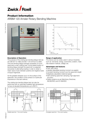
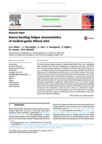
Author's personal copyjournal of the mechanical behavior of biomedical materials 27 (2013) 19 –3221Fig. 1 – (a) Photograph and (b) schematic of the custom-built rotary bend fatigue tester. The environmental-controlled testchamber is not shown. See vertical scale (cm) for relative dimensions.testing machine (Instron Model 5500R) equipped with anenvironmental chamber. An extension rate of 0.5 mm/minwith an extensometer per guidelines in ASTM F2516 (ASTM,2006b) was used at test temperatures of 25, 23 and 60 1C.2.3.Rotary bending fatigue testingRotary bending tests were performed using a guided rotary bendtester as shown in Fig. 1 that was also used for previous studies(Graham and VanDoren, 2004; Sheriff and Pelton, 2005; Wickand Gong, 2005; Morgan and Wick, 2008). The wire specimenswere rotated around a series of fixed diameter mandrels. Themandrels were machined from Delrins Acetal Resin (DuPont)rods to minimize surface wear on the Nitinol wires.Strain amplitudes were estimated by:εα ¼d2ρð1Þwhere d is the wire diameter, and ρ is the radius of curvature ofthe mandrels used. Test temperatures of –25, 23, and 60 1C wereobtained with a temperature-control re-circulating unit. Chilledmethyl alcohol was used for the lowest test temperature( 25 1C), whereas tests at 23 and 60 1C were performed indistilled water. These temperatures were chosen to provide awide range of temperatures that bracket relevant medicaldevice applications. Tests were conducted at a maximumrotational speed of 2000 rpm1 until fracture was detected withthe optical fiber, break-detection system. High-cycle fatiguetests were conducted to a maximum of 107 cycles. A minimumof five wires per strain level was tested for each condition with210 mm wire lengths. The wire fracture surfaces were examinedwith an SEM (JEOL model 5600 or FEI Quanta 200 3D) in both thesecondary electron and back-scattered imaging modes.1For comparison, a limited number of tests were conducted at300 rpm; no discernible differences were observed in the fatiguebehavior of the wires.2.4.Finite element analysisA non-linear Finite Element Analysis (FEA) model of therotary bending loading was developed to determine localstresses and strains in the Nitinol wire subjected to 3601rotations with different bending radii. The commercial FEApackage Abaquss/Standard version 6.12-1 was used in combination with the user-defined material subroutine (UMAT)for these computational analyses. The non-linear mechanicaland thermal input properties for the Nitinol UMAT werederived from the uniaxial tension tests performed on theNi50.8Ti49.2 bright Nitinol wires, per industry practice. Sinceuniaxial compression testing on such fine wire samples is notpossible, the FEA model incorporates the convention ofcompressive transformation stress equal to 1.5 the tensiletransformation stress (Dessault Systèmes, 1658). Table 2provides the parameters used for the FEA that were extractedfrom the uniaxial tensile tests from Fig. 2.3.Results3.1.Uniaxial tensile mechanical propertiesFig. 2 shows the uniaxial stress–strain properties in tension at 25, 23, and 60 1C of the four wires: (a) Ni50.8Ti49.2 bright, (b)Ni50.8Ti49.2 black, (c) Ni50.6Ti49.4 black, and (d) Ni49.5Ti50.5 black.The curves from the Ni-rich compositions show the expecteddifferences in elastic modulus and plateau stress with temperature, whereby both parameters increase with increasingtest temperature. The upper plateau stress rate (ds/dT) isapproximately 5 MPa/1C, comparable to published data frommedical-grade Nitinol pseudoelastic wire (Pelton and DiCelloet al. 2000). Furthermore, the maximum strain at the end ofthe stress plateau for the Ni50.8Ti49.2 and Ni50.6Ti49.4 wiresincreases with increasing test temperature; for example, themaximum plateau strain at 60 1C is 7.5% compared with 6.3%
Author's personal copy22journal of the mechanical behavior of biomedical materials 27 (2013) 19 –32elongation values are comparable for each wire type as wellas among the four sets of wires.The Ni49.5Ti50.5 data show a minimum in tensile plateaustress at 23 1C compared with tests at 25 1C or at 60 1C. Thisat 23 1C for the Ni50.8Ti49.2 bright wires. This observationsupports the increased stability of austenite with respect tothe (stress-induced) martensitic phase transformation attemperatures above Af. The ultimate tensile stress and totalTable 2 – ABAQUS UMAT parameters.Abaqus superelasticity UMAT constantsSymbolExtracted valuesAustenite elasticity (MPa)Austenite poissons ratioMartensite elasticity (MPa)Martensite poissons ratioTransformation dT loading (MPa/1C)End transformation loading (MPa)Reference temperatureds/dT unloading (MPa/1C)sSL494sELT0!δs"557225.1δT UsSUsEUsSCLεLVStart transformation unloading (MPa)End transformation unloading (MPa)Start transform stress compression (MPa)Volumetric transformation strainNumber annealing stepsNumber of stress–strain pairsStress in yield curve (MPa)3363117550041233NANPsP1ε1Strain in yield curveStress in yield curve (MPa)0.0931341sP2ε2Strain in yield curveStress in yield curve (MPa)0.0991432sP3ε3Strain in yield curveStress in yield curve (MPa)0.1061531sP4ε4Strain in yield curve2000True Stress (MPa)5.1δT LStart transformation loading (MPa)0.119Ni50.8Ti49.2Bright SurfaceNi50.8Ti49.2Black Surface1500100060 C60 C23 C23 C-25 C-25 C5000True Stress (MPa)2000Ni49.5Ti50.5Black Surface-25 C23 C60 CNi50.6Ti49.4Black Surface1500100060 C23 C5000-25 C02468True Strain (%)10121402468101214True Strain (%)Fig. 2 – Uniaxial tensile behavior of (a) Ni50.8Ti49.2 Bright, (b) Ni50.8Ti49.2 Black, (c) Ni50.6Ti49.4 Black and (d) Ni49.5Ti50.5 Black,at 25, 23, 60 1C. Note that the plateau stresses of the three Ni-rich alloys increase with increasing test temperature and havesimilar characteristics at each temperature. The Ni49.5Ti50.5 wire tested at 23 1C has the lowest plateau stress due to thepresence of R-phase (see Fig. 3).
Author's personal copyjournal of the mechanical behavior of biomedical materials 27 (2013) 19 –32T -25 CNi50.8Ti49.2 BrightNi50.8Ti49.2 BlackNi50.6Ti49.4 BlackNi49.5Ti50.5 BlackCool66 CHeat10.060 CStrain Amplitude %R-Phase55 C-523 C42 C-6 C5Heat Flow (mW)Martensite50 C-25 C10 ature ( C)Fig. 3 – Thermogram from DSC test of Ni49.5Ti50.5 wires withphase transformation start and finish temperatures as wellas peak phase identification noted. Also shown are the threetest temperatures for tensile and bending fatigue. Thecooling (top) curve dictates the phases for the testing for the 25 and 23 1C tests whereas the heating curve (bottom)shows the phases for the 60 1C tests.105106107108CyclesFig. 5 – Strain amplitude versus number-of-cycles curves at atest temperature of 25 1C for Ni50.8Ti49.2 bright, Ni50.8Ti49.2black, Ni50.6Ti49.4 black, and Ni49.5Ti50.5 black wires. TheNi50.8Ti49.2 bright surface data and trend lines from Fig. 4 arere-plotted in this figure for comparison. Data at 107 cyclesare considered run-out conditions.3.2.Fatigue of Ni50.8Ti49.2 bright wire10.0Ni50.8Ti49.2Strain Amplitude %Bright Surface1.0-25 C23 C60 C0.1102103104105106107108CyclesFig. 4 – Strain amplitude versus number-of-cycles curves forNi50.8Ti49.2 bright wire tested at 25 1C, 23 1C, and 60 1C. Dataat 107 cycles did not fracture and are considered run-outconditions. Trend lines from regression analyses are drawnto delineate strain amplitude regions for these three setsof data.apparent discrepancy is due to the presence of theR-phase2 at room temperature. A differential scanning calorimetric (DSC) thermogram of the Ni49.5Ti50.5 wire, shown inFig. 3, illustrates the test temperatures and phases as well astransformation start and finish temperatures. These Ti-richwires were heated to 100 1C prior to tensile or rotary bendfatigue tests, so the temperature–phase relationships forthe 25 1C and 23 1C tests are dictated by the DSC coolingcurve (top). However, the cooling rate was high enough toallow the wires to cool prior to heating for the 60 1C test;therefore, the DSC heating curve (bottom) better reflects thephase content for these tests.2R-phase is considered a martensitic phase (Otsuka and Ren,2005 with trigonal symmetry (P3) (Khalil-Allafi et al., 2006.Fig. 4 shows strain amplitude vs. cycles fatigue data for theNi50.8Ti49.2 bright wires tested at 25, 23, and 60 1C plotted on alog–log plot. These data show that fatigue behavior is stronglyinfluenced by test temperature, whereby testing at 251 C (RPhase) provides the longest lives at the intermediate-to-highstrain amplitudes as well as the greatest strain amplitude (1%)at 107 cycles. The 60 1C (austenite) fatigue data, on the otherhand, has the shortest low-cycle lives and lowest strain amplitude (0.5%) at 107 cycles. Trend lines from regression analysesare drawn to delineate strain amplitude regions for these threesets of data. Note that there are four distinct regions for thepseudoelastic conditions (i.e., test temperatures of 23 and 60 1C)whereas there are only two regions at 25 1C. Clearly, thedifferences between the fatigue conditions reflect the tensilebehavior of the wires shown in Fig. 2. The fatigue data from theseparate regions are denoted Region I (N 103 cycles for thegreatest strain amplitudes), Region II (N 103 cycles), Region III(103 N 105 cycles for intermediate strain amplitudes), andRegion IV (105 N 107 cycles for the lowest strain amplitudes).These characteristics will be discussed below in more detail. Inthe next sections we will compare the fatigue data from thevarious wire conditions at the three test temperatures.3.3.Fatigue at 25 1CFatigue data for the four material conditions are shown in Fig. 5at 25 1C test temperature. The Ni50.8Ti49.2 bright surface dataand trend lines from Fig. 4 are re-plotted in this figure forcomparison. Remarkably, the data for all wires show similarbehavior at comparable strain amplitudes (see Table 3 forstatistical analyses) and the monotonic stress–strain behaviordictates the overall fatigue response since there is no stressinduced martensite transformation that occurs. The strain-lifeplot appears similar to a typical, non-transforming metallic alloy.All three of the Ni-rich compositions are in the R-phase region,whereas the Ni49.5Ti50.5 wire is fully martensitic at 25 1C
Author's personal copy24journal of the mechanical behavior of biomedical materials 27 (2013) 19 –32Table 3 – Summary of power-law fatigue analysis.Region ITemperature (1C)Region IIIRegion IVβR2βR2βR2Ni50.8Ti49.2 bright wire 252360 0.32 0.420.690.99 0.52 0.32 0.310.930.970.97 0.04 0.03 0.030.670.490.99Ni50.8Ti49.2 black wire 252360 0.56 0.430.530.98 0.47 0.33 0.300.920.970.92 0.05 0.03 0.030.970.430.42Ni50.6Ti49.4 black wire 252360 1.16 0.540.520.89 0.49 0.35 0.380.860.920.94 0.05 0.05 0.040.610.911.00 0.48 0.62 0.710.830.930.89 0.05 0.09 0.070.820.980.86Ni49.5Ti50.5 black wire 25236010.0T 23 CNi50.8Ti49.2 BrightNi50.8Ti49.2 BlackNi50.6Ti49.4 BlackNi49.5Ti50.5 BlackStrain Amplitude %Strain Amplitude %10.0Sheriff, EPReinoehl, Black1.00.11021031041051061071.00.1102108T 60 CNi50.8Ti49.2 BrightNi50.8Ti49.2 BlackNi50.6Ti49.4 BlackNi49.5Ti50.5 Black103Cycles104105106107108CyclesFig. 6 – Strain amplitude versus number-of-cycles curves at atest temperature of 23 1C for Ni50.8Ti49.2 bright, Ni50.8Ti49.2black, Ni50.6Ti49.4 black and Ni49.5Ti50.5 black wires. Alsoincluded in this figure are data from Sheriff et al. from forNi50.8Ti49.2 electropolished wires (Sheriff and Pelton, 2005) andfrom Ni50.8Ti49.2 black wires with two ingot sources (Reinoehlet al., 2001). The Ni50.8Ti49.2 bright surface data and trend linesfrom Fig. 4 are re-plotted in this figure for comparison. Dataat 107 cycles are considered run-out conditions.Fig. 7 – Strain amplitude versus number-of-cycles curves at atest temperature of 60 1C for Ni50.8Ti49.2 bright, Ni50.8Ti49.2black, Ni50.6Ti49.4 black, and Ni49.5Ti50.5 black wires. TheNi50.8Ti49.2 bright surface data and trend lines from Fig. 4 arere-plotted in this figure for comparison. Data at 107 cyclesare considered run-out conditions.(as indicated in Fig. 3). The 107-cycle fatigue strain limit is 1%under these test conditions.3.5.3.4.Fatigue at 23 1CThe fatigue data for the four material conditions are shown inFig. 6 at the 23 1C test temperature. The Ni50.8Ti49.2 bright dataand trend lines from Fig. 4 are re-plotted in this figure forcomparison. The Ni50.8Ti49.2 black and Ni50.6Ti49.4 black wires alsofollow similar trends to Ni50.8Ti49.2 bright wire data. For comparison, Ni50.8Ti49.2 wire fatigue data from Reinoehl et al., (2001)(black) and Sheriff and Pelton (2005) (electropolished) are alsoshown in this figure. The Ni49.5Ti50.5 wires (R-Phase) showedlonger lives in the low-cycle fatigue region and a greater fatiguestrain limit in the high-cycle fatigue region.Fatigue at 60 1CThe fatigue data for the four material conditions are shown inFig. 7 at 60 1C. The Ni50.8Ti49.2 bright surface data and trendlines from Fig. 4 are re-plotted in this figure for comparison.Note that the data for the Ni50.8Ti49.2 bright and black surfaceconditions as well as the Ni50.6Ti49.4 black fall on top of eachother, indicating that there is no significant differencebetween these surface conditions. In contrast, the Ni49.5Ti50.5wires showed longer lives in the low-cycle fatigue region anda greater fatigue strain limit in the high-cycle fatigue region.As shown on the DSC curve in Fig. 3 the Ti-rich wires containa two-phase mixture of austenite and martensite at 60 1C.
Author's personal copyjournal of the mechanical behavior of biomedical materials 27 (2013) 19 –3225Fig. 8 – SEM images of the fracture surfaces for Ni50.8Ti49.2 bright wire tested at room temperature at strain amplitudes of 1%(11,931 cycles, Region IV), 2% (2039 cycles, Region III), 5% (1487 cycles, Region II) and 10% (520 cycles, Region I). Note that thesize of the fatigue fracture area increases as the strain amplitude decreases.Fig. 9 – SEM images of the fracture surfaces for Ni49.5Ti50.5 black wire tested at room temperature at strain amplitudes of 0.94%(7,946,029 cycles), 2% (16,031 cycles), 5% (3084 cycles) and 10% (1546 cycles).3.6.Fracture surfacesSEM images of the fracture surfaces are shown in Figs. 8 and 9for the Ni50.8Ti49.2 bright wire and Ni49.5Ti50.5, respectively, at fourstrain amplitudes that correspond to the four superelasticfatigue regions: Region IV – 1%, Region III – 2%, Region II – 5%,and Region I – 10%.4.Discussion4.1.Monotonic and bending mechanical propertiesThe uniaxial tensile properties of the Nitinol wires shown inFig. 2 can be used as an approximate guide for the cyclicbending behavior. However, there are a number of differencesthat should be considered that limits the ability to quantify the
Author's personal copy26journal of the mechanical behavior of biomedical materials 27 (2013) 19 –32data. First, the use of mandrels to guide the wires into thedefined curvature has the effect of creating a larger region ofwire that is subjected to the same strain amplitude. As shownby Berg (1995) and Wick and Vöhringer (1995), pure (unconstrained) bending of pseudoelastic Nitinol creates non-circulararcs on the stress-induced martensite plateau. These macroscopic facets are due to regions that are either deformedaustenite or stress-induced martensite. Consequently, it isdifficult to ascribe an absolute strain to this transformingregion under free rotating bending conditions. Second, Nitinoldisplays an anisotropy in tension vs. compression behavior.The phenomenological theory of martensitic transformationshas been used effectively to model tension-compressionasymmetry and the orientation dependence of the deformation behavior of Nitinol (Buchheit and Wert, 1994, 1996; Galland Sehitoglu, 1999a; Gall and Sehitoglu, 1999b). These analyses show that the martensite variants created in tension aredifferent from those created in compression, which give rise todifferences in plateau stresses, shape memory recoverystrains, and critical resolved shear stresses. Third, there arefew direct experimental comparisons between the tensile andbending properties of Nitinol so calculation of bending curvesfrom uniaxial data is not straightforward. Plasticity theory hasbeen applied to a pseudoelastic beam to estimate bendingproperties from tension data (Atanacković and Achenbach,1989; Wick and Vöhringer, 1995). The upper plateau stress intension, sUP, and the elastic strain limit, εel ¼sUP/E, where E isthe elastic modulus, were the only parameters used to calculate the bending stress, sb. Wick and Vöhringer demonstratedthat the modulus of pseudoelastic Nitinol in tension andbending are equivalent based on extensive investigationsunder pure- and four-point-bending conditions with straingage instrumentation (Wick and Vöhringer, 1995). They furthershowed that the above relationship worked well to relate theupper plateau stresses from tensile tests to bending stressesand were comparable to the theoretical ratio of 1.7. However,there were significant discrepancies in the calculated unloading plateau stresses compared to the experimental data.Wagner and Eggeler (2006a, 2006b) used numerical calculationsto show that the stress and strain states differ significantlybetween pure bending and bending rotation of pseudoelasticNitinol wires. However, their models neglected to take intoaccount the tension-compression asymmetry that thereforeunderestimates the compression stresses. Furthermore, arecent publication by Reedlunn and Churchill (2012) investigated the surface strain evolution of Nitinol tubing (DSC Af of19 1C) under tension, compression and bending conditions atroom temperature with stereo digital image correlation. Theirresults clearly showed the asymmetry in uniaxial tension andcompression (where their compression plateau stress is 1.5 the tension plateau stress). Furthermore, the stress plateau intension was relatively flat and 5.45% in length whereas incompression the plateau has an upward slope with 3.49%length. Their four-point bending testing provided momentcurvature curves similar to those shown by Wick andVöhringer (1995) with the bending-tension plateau ratio of 1.69, also comparable to the theoretical ratio. Furthermore,their model showed reasonable agreement with the bendingloading curves predicted from tension-compression data(although they did not predict unloading curves).4.2.Finite element analysisThe commercial non-linear FEA code used in this investigation offers insight into the relative behavior of the wiresunder rotary bending test conditions. Fig. 10 shows FEA straincontours calculated for the Ni50.8Ti49.2 bright wires in crosssection for strain amplitudes of 1, 2, 5, and 10% that representthe four distinct strain regions from Fig. 4 at 23 1C. The straincolor levels were normalized to the 10% strain amplitudecondition, although in each case the compressive strainswere greater than the tensile strains. Stress–strain curvesfor these wires are presented in Fig. 11 from the FEA simulations. These results depict the tension-compression characteristics for the conditions of the cyclic deformation. Inagreement with prior tensile-compressive testing of pseudoelastic Nitinol, the compressive stress plateau is 1.5 greaterthan that of the tensile plateau stress, per defined materialparameters. As such, the compressive elastic region is greaterthan the tensile elasticity. For example, at 1% strain, thetensile conditions lead to a small stress hysteresis whereason the compressive side of the cycles, the wires are still in thelinear elastic region. At 2 and 5% strain amplitudes, thetensile stress hysteresis is again greater than that on thecompressive side. At 10% strain amplitude there is approximately 0.7% remnant strain (permanent set) on the tensilecycle unloading, whereas the wire does not reach compressive yield at this strain amplitude. Therefore, based on theseFEA curves, it is likely that the compressive cycling leads togreater damage accumulation than tensile cycling due togreater stress amplitude per cycle. Although still underdevelopment (Stebner and Bhattacharya, 2013; Stebner andBrinson, 2013), non-linear FEA that takes into account micromechanical modeling of the uniaxial tension and compression behavior may provide a more accurate model of rotatingbend fatigue and other multi-axial deformation of Nitinol.4.3.Fatigue of Ni50.8Ti49.2 bright wireWe will use the fatigue data from Fig. 4 (as well as the FEAresults in Fig. 11) to examine the genera
2006b) was used at test temperatures of 25, 23 and 60 1C. 2.3. Rotary bending fatigue testing Rotary bending tests were performed using a guided rotary bend tester as shown in Fig. 1 that was also used for previous studies (Graham and VanDoren, 2004 ; Sheriff and Pelton, 2005 ; Wick and Gong, 2005; Morgan and Wick, 2008). The wire specimens