Transcription
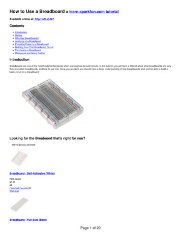
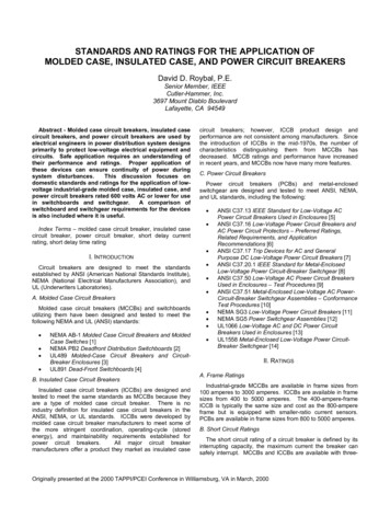
Build Your FirstBreadboardCircuitThis simple circu it turnson a light- emitting diode(LED).
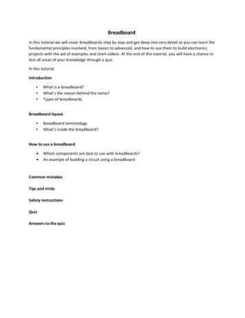
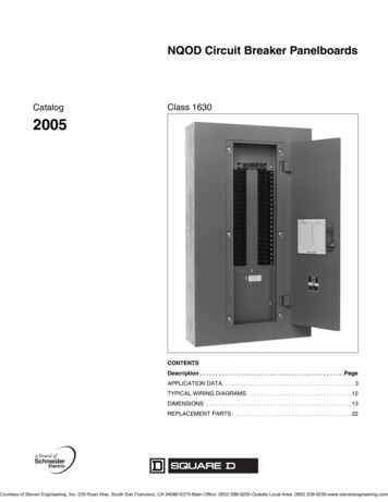
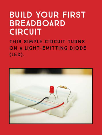
The C irc u it Dia gr a m resistorbattery led The Pa rts ListPa r tVa l u eDescriptionBattery9VStandard 9 V batteryBattery clipComponent that connects thebattery to the breadboardBreadboardPlastic board with around 400 holesResistor470 ΩComponent that reduces the currentthrough the LEDLEDRedStandard-output light-emitting diodeTwo breadboard jumper wires indifferent colorsJumper wiresB u ild in g the C ir cuitTo build this circuit, all you need is a battery, a resistor, and an LED.The resistor reduces the amount of current that flows through theLED. You’ll always want a resistor in series with an LED, but it doesn’tmatter whether you place it before or after the LED. When you adda resistor in series with a circuit, you get less current in the wholecircuit. If you don’t use a resistor, you risk breaking the LED.Connecting the ResistorFor this circuit, you’ll need a resistor of 470 Ω, or ohms. If you lookclosely at a resistor, you’ll notice it has several colored bands. Thesecolors tell you the value of the resistor. To find a 470 Ω resistor, lookfor a resistor that has colored bands in this order: yellow, purple,brown, and gold or silver (see Figure 1).Figure 1A 470 Ω resistor1 1 B u i l d Yo u r F i r s t B r e a d b o a r d C i r c u i t
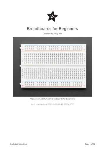
NOTEIn “Resistor Color Codes”on page 64, you’ll finda table that explains thecolor coding of a resistor.Connect one pin of the 470 Ω resistor to the top row of columnF and attach the other pin to row 7 in the same column, as shownin Figure 2. It doesn’t matter which pin you place where; the resistorcan be connected either way around.Figure 2Connecting the resistorto the breadboardConnecting the LEDNow you’ll connect your LED to the breadboard. An LED has twosides, called anode and cathode. For the LED to work, you needto connect the anode to the positive side ( ) of the battery and thecathode to the negative side (–). For simplicity’s sake, let’s call themthe positive pin and the negative pin of the LED. I’ve marked themin Figure 3.Figure 3An LED with its positiveand negative pins1 2 B u i l d Yo u r F i r s t B r e a d b o a r d C i r c u i t
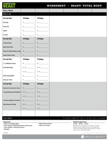
There are two ways to tell which pin is which. Look closely atyour LED. If one pin is longer than the other, that’s the positive side.If both pins are the same length, look more closely at the round edgeat the bottom of the plastic housing. One side of the housing shouldbe flat, as in Figure 3; that’s the negative pin. If you’re still having ahard time distinguishing between the two pins, place the LED on aflat surface and roll it so you can find the flat side.Connect your LED’s positive pin to column H, row 7, and thenconnect the negative pin to column H, row 10. Check your connections against Figure 4.Figure 4Connecting an LED inseries with a resistorNow the positive pin of the LED is connected to the resistor—asshown in the circuit diagram—but the negative pin, like the upper pinof the resistor, isn’t connected to anything.Connecting to the Power Supply ColumnsNext you need to connect wires from the power supply area on theright side of the breadboard to the appropriate rows in the right-handcomponent area.If you look at the circuit diagram again, you can see that you needto connect the positive terminal of the battery to the top-most lead ofthe resistor—the lead in row 1. So use a jumper wire to connect row 1to the positive column in the supply area. It’s common to use the column with a red line next to it as the positive one (to match the red wireof the battery clip). Then connect the LED’s negative pin—in row 10—to the negative column in the supply area. Use Figure 5 as a reference.1 3 B u i l d Yo u r F i r s t B r e a d b o a r d C i r c u i t
Figure 5Connecting thecomponent area tothe supply area of abreadboardConnecting the BatteryYou have your components in place, and you’ve properly connectedthe components to the supply area. Now you only need to connect the battery.First, connect your battery clip to your battery, making sure theexposed metal of the red and black wires does not touch. Next, connect the red wire from your battery clip to the positive column of theright-hand supply area. Finally, connect the black wire from your battery clip to the negative column. Check your circuit against Figure 6.Figure 6Connecting a batteryto a breadboard’ssupply areaThe LED should now be lit up!1 4 B u i l d Yo u r F i r s t B r e a d b o a r d C i r c u i t
What If the LED Does Not Light Up?If your LED isn’t lighting up, go through each connection on thebreadboard to make sure everything is exactly as described in theprevious steps.If you’ve connected everything correctly and it’s still not working,you might have connected the LED the wrong way. Flip it around andtry again.If it’s still not working, check the resistance value of your resistorusing the table in “Resistor Color Codes” on page 64. Your resistorshould be 470 Ω.Still not working? Well, then your LED is likely dead, unfortunately.This can happen easily if you connect it directly to the battery—thatis, without putting it in series with a resistor. Replace your LED andtry again.Yo u ’ r e R e a dy to Bui ld theN in e Cir c ui ts!Now that you’ve built your first breadboard circuit, you’re almostready to move on to this book’s nine circuit projects. First, though, Irecommend that you play around a little with the circuit you built inthis chapter. Try to really understand why those connections makethe circuit work. Understanding this is crucial to building the restof the circuits in this book. A good test is to see if you can build thecircuit again in the left-hand component and power supply areas, justby looking at the circuit diagram.For all the circuits in this book, you’ll need a breadboard, a bunchof breadboard jumper wires, a battery, and a battery clip. But for simplicity’s sake, you won’t see these components in the parts list.The circuits are sorted by difficulty, starting from the easiest. Thechallenge is to figure out how to connect each of the circuits on thebreadboard. Some of the later circuits might be challenging if youdon’t have any previous experience with circuits, but the trick is tonot give up.You can find resources for all the circuits through the book’swebsite at https://nostarch.com/circuits/.1 5 B u i l d Yo u r F i r s t B r e a d b o a r d C i r c u i t
Breadboard Plastic board with around 400 holes Resistor 470 Ω Component that reduces the current through the LED LED Red Standard-output light-emitting diode Jumper wires Two breadboard jumper wires in different colors BuiLDing The CirCuiT To build this circuit