Transcription
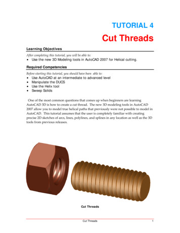
TUTORIAL 4Cut ThreadsLearning ObjectivesAfter completing this tutorial, you will be able to: Use the new 3D Modeling tools in AutoCAD 2007 for Helical cutting.Required CompetenciesBefore starting this tutorial, you should have been able to: Use AutoCAD at an intermediate to advanced levelManipulate the DUCSUse the Helix toolSweep SolidsOne of the most common questions that comes up when beginners are learningAutoCAD 3D is how to create a cut thread. The new 3D modeling tools in AutoCAD2007 allow you to model true helical paths that previously were not possible to model inAutoCAD. This tutorial assumes that the user is completely familiar with creatingprecise 2D sketches of arcs, lines, polylines, and splines in any location as well as the 3Dtools from previous releases.Cut ThreadsCut Threads1
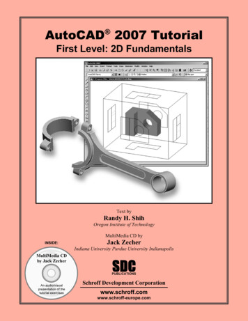
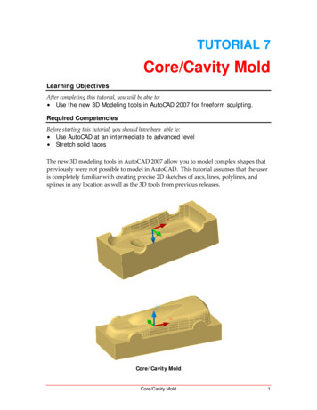
1. Open the file named Tutorial 4 Threads.dwg. We are going to cut M10 x 1.5threads. Check the Machinery’s Handbook for complete information on threadforms.Figure 12. Turn off all layers except the Rod Sketch and Rod Solid layers and makethe Rod Solid layer the active layer. Revolve the Rod Sketch as shown.Figure 22Tutorial 4Copyright 2006, J.D. MatherPennsylvania College of Technology
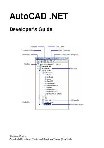
3. Turn on the External Threading Tool and Helix Path layers, Make the Helix Pathlayer the active layer. Select the Helix tool and then select the Center snap pointof the end of the rod. (Tip: By selecting a circle center point we automatically set thez‐axis perpendicular to the circle if DUCS is turned on.)Figure 34. Then select the Intersection of the corner of the cutting tool as the base radius.Press enter to accept the same distance as the top radius.Figure 4Cut Threads3
5. RMB select turn Height and enter a height of 1.5 for the pitch of the thread.Figure 56. And then track along the axis going a couple of turns beyond the end of the rod.(Tip: If your z‐axis happens to be pointing in the wrong direction you can track the axisof the helix by pausing over the center of the start end and then tracking in desireddirection of the axis.)Figure 64Tutorial 4Copyright 2006, J.D. MatherPennsylvania College of Technology
7. Start the Sweep tool and select the cutting tool sketch. Then RMB and selectAlignment and No. Then select the helical path.Figure 78. If you are going to rapid prototype the part via an stl file you might want tomake a copy of the thread cut shifted along the axis the desired clearancedistance.Figure 8Cut Threads5
9. Subtract the Sweep and make sure the rod is on the Rod Solid layer and turn offthe other layers.Figure 910. Turn off all layers except the Nut Sketch and Nut Solid layers and make the NutSolid layer the active layer.Figure 106Tutorial 4Copyright 2006, J.D. MatherPennsylvania College of Technology
11. Extrude the hexagon to the center of the second circle as shown. (Tip: Shown inFigure 11 in x‐ray visual style mode.Figure 1112. Presspull the hole through the part.Figure 12Cut Threads7
13. Extrude the larger circle that is tangent to the hexagon with a taper of 45 (or 45 )beyond the length of the nut.Figure 1314. Use the Intersection tool to derive the intersection between the two solids. Thiscuts a chamfer on the nut.Figure 148Tutorial 4Copyright 2006, J.D. MatherPennsylvania College of Technology
15. Repeat the same procedure on the other side.Figure 1516. Add a 0.75mm Chamfer to both ends of the hole in the nut.Figure 16Cut Threads9
17. Turn the Internal Threading Tool layer on. Create a new Helix path for theinternal threading tool.Figure 1718. Sweep the cut tool and subtract as was done with the external thread.Figure 1810Tutorial 4Copyright 2006, J.D. MatherPennsylvania College of Technology
Figure 19That completes the internal and external cut threads. Remember you might want to cutclearance if you are going to rapid prototype your cut thread parts. Keep in mind that RPprocesses are not as accurate as machined processes and may require a more liberalclearance.Cut Threads11
AutoCAD 3D is how to create a cut thread. The new 3D modeling tools in AutoCAD 2007 allow you to model true helical paths that previously were not possible to model in AutoCAD. This tutorial assumes that the user is completely familiar with creating