Transcription
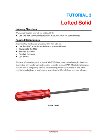
TUTORIAL 3Lofted SolidLearning ObjectivesAfter completing this tutorial, you will be able to: Use the new 3D Modeling tools in AutoCAD 2007 for basic Lofting.Required CompetenciesBefore starting this tutorial, you should have been able to: Use AutoCAD at an intermediate to advanced levelManipulate the UCSExtrude SurfacesRevolve SurfacesLoft Solids.The new 3D modeling tools in AutoCAD 2007 allow you to model complex freeformshapes that previously were not possible to model in AutoCAD. This tutorial assumesthat the user is completely familiar with creating precise 2D sketches of arcs, lines,polylines, and splines in any location as well as the 3D tools from previous releases.Screw DriverLofted Solid1
1. Open the file named Tutorial 3 Screw Driver.dwg.Figure 12. Turn off all layers except the Handle Base Sketch layer, the Handle Solidlayer, and the Construction layer. Make the Handle Solid layer the activelayer. Set the “delobj” variable to 0 so that the sketches will not beconsumed. That way if you make a mistake you can go back to theoriginal geometry. Sweep the red profile along the yellow centerline path.(This is fewer mouse clicks than extrude along path.)Figure 22Tutorial 3Copyright 2006, J.D. MatherPennsylvania College of Technology
3.Make the Revolve layer visible and Revolve the two white sketches.Figure 34. Select Slice in the Dashboard and click on the solid, then Enter. RMB selectSurface and then click on one of the revolved surfaces and then the middleportion of the solid to retain that portion. Repeat the procedure for the otherend.Figure 4Lofted Solid3
5. In the Visual Styles control panel of the Dashboard select Realistic as the shadestyle.Figure 56. Change to the front view and set the UCS to the face in the middle of the view.Create text of your choice and use the Express tool Explode text to turn it intopolylines.Figure 64Tutorial 3Copyright 2006, J.D. MatherPennsylvania College of Technology
7. Move the cursor arrow to the area of the Make 3D control panel in theDashboard as shown in Figure 7 and select Imprint. Click on the solid and theneach of the polylines. (You may elect to keep the polylines for future use or deletethem.)Figure 78. From the Solids Editing toolbar select Color Faces and change the color of theimprinted faces. Turn off the visibility of the Handle Solid layer.Figure 8Lofted Solid5
9. Turn on the visibility of the Blade Cross sections layer, the Blade Guides layer,and the Blade Solid layer. Make the Blade Solid layer the active layer.Figure 910. Loft the green cross‐sections along the cyan Guide wires.Figure 106Tutorial 3Copyright 2006, J.D. MatherPennsylvania College of Technology
11. Make the Blade Flare layer visible and select Extrude.Figure 1112. You do not need to enter a specific height for the extrusion – simply drag it outany distance beyond the edge of the blade.Figure 12Lofted Solid7
13. Make one of the grips active and Move the surface to along the z‐axis in theimage so that it cuts all the way through the solid. (Tip: You can now track along x,y, or z axis.)Figure 1314. If you need to stretch a surface simply grab the arrow shaped grip and stretchthe surface through the solid as needed.Figure 148Tutorial 3Copyright 2006, J.D. MatherPennsylvania College of Technology
15. Use the surface to Slice the solid and then move the surface to the Hide Surfaceslayer.Figure 1516. Make the Blade Grind layer visible and Extrude the blue wires.Figure 16Lofted Solid9
17. Move the extruded surface down so that it cuts completely through the bladeand then use the surface to Slice the blade.Figure 1718. Copy the blade so that there are two solid blades in the exact same location.Figure 1810Tutorial 3Copyright 2006, J.D. MatherPennsylvania College of Technology
19. Turn the Handle Solid layer back on. Subtract the copied Blade solid from theHandle. Turn off the Blade Solid layer to make sure you have the appropriatehole in the handle.Figure 1920. Turn the Blade layer back on and save your file.Figure 20Lofted Solid11
TUTORIAL 3 Lofted Solid Learning Objectives After completing this tutorial, you will be able to: Use the new 3D Modeling tools in AutoCAD 2007 for basic Lofting. Required Competencies Before starting this tutorial, you should have been able to: Use AutoCAD at an intermediate to advanced level Manipulate the UCS Extrude Surfaces