Transcription
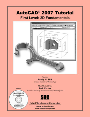
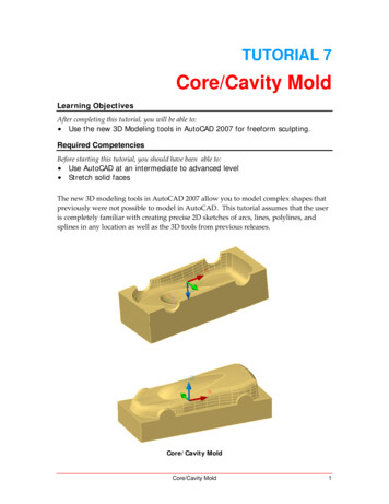
TUTORIAL 7Core/Cavity MoldLearning ObjectivesAfter completing this tutorial, you will be able to: Use the new 3D Modeling tools in AutoCAD 2007 for freeform sculpting.Required CompetenciesBefore starting this tutorial, you should have been able to: Use AutoCAD at an intermediate to advanced level Stretch solid facesThe new 3D modeling tools in AutoCAD 2007 allow you to model complex shapes thatpreviously were not possible to model in AutoCAD. This tutorial assumes that the useris completely familiar with creating precise 2D sketches of arcs, lines, polylines, andsplines in any location as well as the 3D tools from previous releases.Core/Cavity MoldCore/Cavity Mold1
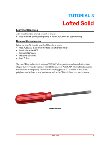
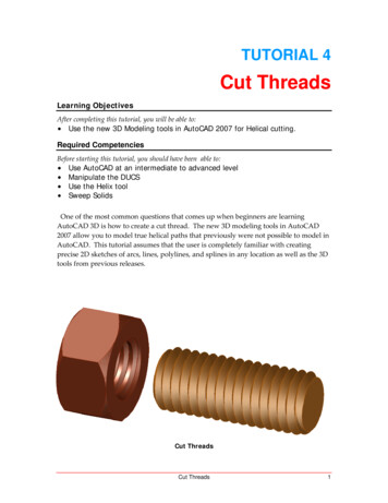
1. Open the file named Toolbody.dwg. Union the two cylinders to the car body.Figure 12. Make new layers named Core and Cavity. Make the Core layer the active layer.Select the Box command and create a box from the center of one end of one of thecylinders to the diagonal center of another cylinder end. Make the height 75mmgoing away from the car body.Figure 22Tutorial 7Copyright 2006, J.D. MatherPennsylvania College of Technology
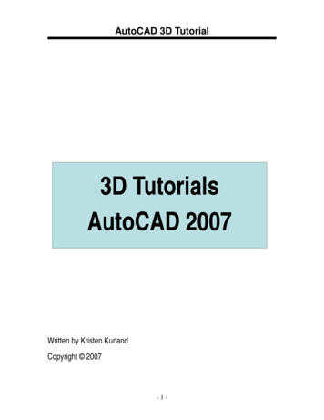
3. Holding the Ctrl key select the end of the box and then select the handle in themiddle of the face. Stretch the face tracking straight back a distance of 100mm.Figure 34. Turn the parts around and repeat the same procedure on the other end.Figure 4Core/Cavity Mold3
5. Union the base to the body.Figure 56. Make the Cavity layer the active layer. Create a Box from corner to diagonalcorner of the base and a height of 125mm.Figure 6A4Tutorial 7Copyright 2006, J.D. MatherPennsylvania College of Technology
7. Read this step carefully before continuing. Turn the assembly over. Copy theCore side in the same location so that there are two core bodies. Then Subtractone of the cores from the Cavity side. Turn off the visibility of the Core layer andthe Cavity should look like Figure 7.Figure 78. Turn off the Cavity layer and turn the Core layer back on and make it the activelayer.Figure 8Core/Cavity Mold5
9. Minimize the Toolbody file and open the Tutorial 6 Toy Car file. Turn on theMounting Posts layer.Figure 910. Extrude the four sketch wires with a taper of ‐3 and a distance of 100mm.Figure 106Tutorial 7Copyright 2006, J.D. MatherPennsylvania College of Technology
11. Read this step carefully. Make a Copy of the car body in the same location.Subtract the car body from the four posts in one operation.Figure 1112. Separate the upper portion of the posts from the lower portion.Figure 12Core/Cavity Mold7
13. Delete the upper portion of the posts and then Union the lower posts to the body.Copy the Car Body to the clipboard with basepoint (0,0,0). Save and close thefile.Figure 1314. Paste the car body into the Toolbody in the (0,0,0) location. Save the file, if it isgoing to crash the next operation is a likely time.Figure 148Tutorial 7Copyright 2006, J.D. MatherPennsylvania College of Technology
15. Subtract the car body from the core. The subtract operation may take severalminutes – and unfortunately on my machine it did not result in the propergeometry with the car body including the mounting posts subtracted from thecore.Figure 1516. Examine the results carefully. We have removed the material from the core thatwould be filled with plastic between the two halves of the mold. (Tip: You shouldhave noticed I changed some face colors as we went along – don’t let the changes of colorsconfuse you.)Figure 15Core/Cavity Mold9
Of course there is much more to mold design that what we have done here. We did notconsider shrinkage or other parts of the tool.10Tutorial 7Copyright 2006, J.D. MatherPennsylvania College of Technology
TUTORIAL 7 Core/Cavity Mold Learning Objectives After completing this tutorial, you will be able to: Use the new 3D Modeling tools in AutoCAD 2007 for freeform sculpting. Required Competencies Before starting this tutorial, you should have been able to: Use AutoCAD at an intermediate to advanced level Stretch solid faces