Transcription
Ellipsometry as a Real-Time Optical tool for Monitoringand Understanding Graphene Growth on MetalsSUPPORTING INFORMATIONMaria Losurdo*, Maria M Giangregorio, Pio Capezzuto and Giovanni BrunoInstitute of Inorganic Methodologies and of Plasmas, National Council of Research, IMIP-CNR,via Orabona 4, 70126 Bari, Italy1
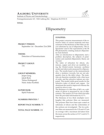
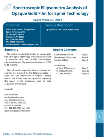
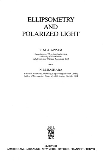
SUPPORTING INFORMATION PARAGRAPHSample Preparation and Experimental setupGraphene was grown by chemical vapor deposition (CVD) from a mixture of CH4 : H2 100:50 sccmgases at a temperature of 900 C and at a total pressure of 4 Torr in a stainless-steel CVD reactor.Growth times between 2 and 15 min were used to vary the thickness of the few-layer graphene (FLG)between approximately 3 Å and 25 Å (this is an optical equivalent thickness, corresponding to Ramananalysis showing between 1-8 layers). The sample is then cooled at a rate of 2 C/min in 1 Torr of H2.300nm Ni/300nm SiO2/Si obtained by Ni sputtering was used as substrate. It was pre-annealed at 400 Cin UHV for nickel oxide desorption for a time of 5-15min and then heated to 900 C in 1 Torr of H2over a period of 40-60 before addition of methane.The graphene growth process was monitored in real-time by an in-situ phase modulated spectroscopicellipsometer (UVISEL, Horiba Jobin-Yvon) integrated on the CVD reactor as shown in Figure S1.SpectroscopicellipsometerSource headCVD psometry lightspot probing duringgraphene depositionNi substrate duringgraphene depositionFigure S1. The UVISEL phase-modulated spectroscopic ellipsometer integrated on the CVD reactor tomonitor graphene formation on nickel . The inset shows the white light spot on the nickel samples at900 C during graphene growth2
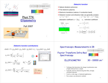
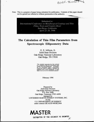
Real Time Spectroscopic Ellipsometry.Ellipsometry is based on measurements of the changes in light polarization upon reflection from asample surface [M. Losurdo, M. Bergmair, G. Bruno, D. Cattelan, C. Cobet, A. de Martino, K.Fleischer, Z. Dohcevic-Mitrovic, N. Esser, M. Galliet, R. Gajic, D. Hemzal, K. Hingerl, J. Humlicek, R.Ossikovski, Z.V. Popovic, O. Saxl J. Nanopart. Res. 2009, 11, 1521]. Linearly polarized light withknown polarization impinges on the samples at an angle of incidence (70 in the present case),becoming elliptically polarized upon reflection depending on the optical properties of the surface.Indeed, the two components of the electromagnetic field-in the plane of incidence (p), and perpendicular(s) to the plane of incidence-experience different attenuationand phase shifts at the reflection (seeFig. S2). Those variations are described by tanΨ that represents the absolute value, while the phasechange between the two polarization is related to cos related to the material refractive index throughFresnel’s law, being ρ the complex reflection coefficient for the parallel, p, and perpendicular, s,polarizations, defined as:ρ tanΨej rp/rsBecause rp and rs are linked, the material’s optical properties can be derived as a function of therecorded wavelengthsErpEipErsLight sourceEisN0N1Figure S2. Scheme of the working principle of ellipsometry: linearly polarized light impinging on asurface and becoming elliptically polarized upon reflection.3
Therefore, spectroscopic ellipsometry monitored in real-time the growth by directly recording thepseudodielectric function ε ε1 i ε2 , which is related to the graphene pseudoextinctioncoefficient k and refractive index n by the following equation (1 ρ )2 〈(n ik )2 〉〈ε 〉 〈ε 1 〉 i 〈ε 2 〉 sin 2 φ 1 tan 2 φ (1 ρ )2 where φ is the angle of incidence fixed at 70 Kinetic ellipsometric data were acquired every 1 s using a phase-modulated spectroscopic ellipsometer(UVISEL, Horiba Jobin Yvon) in the 1.5-5.5 eV spectral range with a 0.01 eV resolution.Analysis of the ellipsometric spectra to extract the optical constant of the graphene layers requires theapplication of an appropriate optical model to fit experimental data. The model used consisted in a onelayer model (substrate/graphene/air). Fit variables in this model are the thickness and theparameterization for the optical constant of graphene. To improve accuracy on the graphene opticalproperties, it is important that the substrate properties are also well known. Therefore, for the hightemperature substrate data (at the growth temperature) the in situ spectrum recorded for the Ni/SiO2/Sisystem just before introducing CH4 into the reactor as been used (spot position is always the same). Forthe room temperature data, in some experimental runs, the substrate has been cooled down after thecleaning and crystallization process. The temperature effect on the dielectric function and opticalproperties of polycrystalline Ni are shown in the Figure S3.The isotropy assumption has been used as already argued and demonstrated in ref. [Nelson, F. J.;Kamineni, V. K.; Zhang, T.; Comfort, E. S.; Lee, J. U.; Diebold A. C. Appl. Phys. Lett. 2010, 97,253110] because the difference in path lengths of light traversing in different directions due tobirefringence in such thin monolayers is negligible. The isotropy assumption still keeps valid the outputfor close-loop control of the graphene thickness. The isotropy assumption also applies to the nickelsubstrate as demonstrated in ref. [P.B. Johnson, R.W. Christy, Phys. Rev. B, 9, 5056 (1994)].4
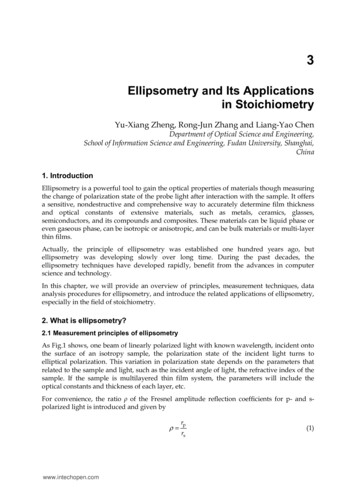
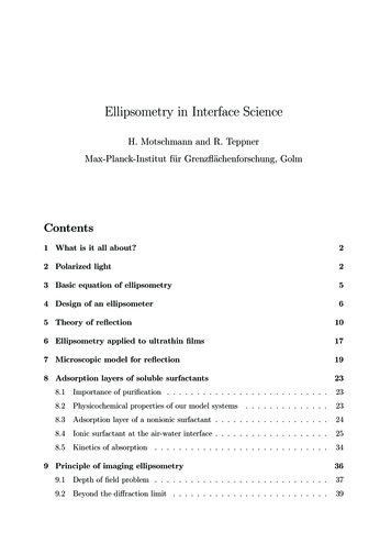
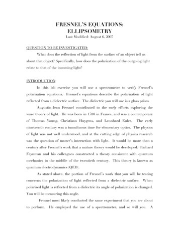
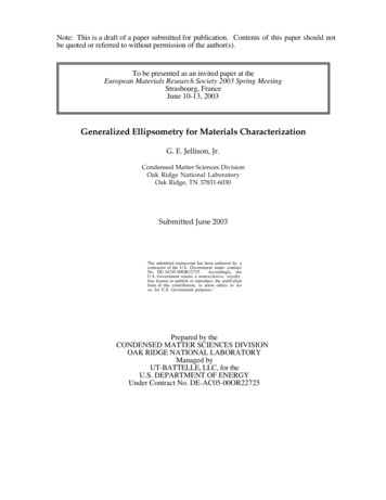
300nm Ni/300nm SiO2/Si catalyst substrate optical behaviorSensitivity of the optical spectra to Ni quality. Figure S3 shows the dielectric function spectraacquired for 300nm Ni/300nm SiO2/Si substrates that underwent a slightly different crystallizationprocess. The differences observed show the sensitivity of the optical spectra to the quality of thecrystalline nickel. The closest the dielectric function to the reference Ni surface, the better the quality ofthe crystallization process. The Ni reference is from ref. 16.2G2304-2-4 ε1 3 k G15Ä r -6k-8 G19G19-10Ni.ref2G15-12-14Ni.refG23234Photon Energy (eV)15Figure S3. Ellipsometric spectra of the real part, ε1 , of the pseudodielectric function and of thepseudoextinction coefficient, k , of Ni substrates (G19) pre-annealed at 400 C for 10 min and thenannealed at 900 C for 5min (blue lines), (G15) pre-annealed at 350 C for 20 min then with a prolongedannealing at 900 C for 40min (black crosses and dots) and (G21) directly annealed at 900 C for 1h (redlines). For comparison, the optical properties of reference Nickel from ref. 16 are also shown.Temperature variation of the system optical properties. We have established the effect of thetemperature on the variation of the optical properties of the Ni substrate. Those are important to avoidany assumption about the substrate to be used in the modeling of data to extract the graphene opticalthickness and optical constant. Figure S4a shows typical crystallization kinetics of the Ni substrate when5
increasing the temperature from room temperature (RT) to 900 C in H2, and the thermal dependence ofthe crystallized Ni optical properties in the range 900 C-RT. The 900 C optical constants, shown in Fig.4Sb, have been used for the analysis of the growth kinetic data recorded at 900 C; the RT opticalconstant are used for analysis of FLG (few-layers graphene) samples at RT.Ni annealing &crystallizationRTCooling downNi thermal variation900 CRT2Ni @900 CNi @RT242.5n1.51.511(a)01.0002.000Time (s)3.000kn3k21.52(b)234Photon Energy (eV)5Figure S4. Variation of the optical properties of the crystallized 300nm Ni/300nm SiO2/Si substrate (a)in kinetic mode cooling down the sample from 900 C to room temperature (RT): thermal variation inthe range 900 C RT causes a k of 0.12 @ 4.2 eV, a n of 0.12 and a ε1 of 0.044. Thisminimal effect of the temperature variation can also be seen in the comparison of the full spectra of thecrystallized nickel recorded at 900 C and at room temperature (RT).Similarly, we have also measured the temperature dependence of the optical properties ofFLG/300nmNi/300nm SiO2/Si samples. Figure S5 compares the spectra of the Ni supported FLG asrecorded at 900 C and at RT.6
04Ä r3.5-4FLG on Ni @900 CFLG on Ni @25 C3 k ε1 -2k-62.5-82234Photon Energy (eV)5Figure S5. Ellipsometric spectra of the real part, ε1 , of the pseudodielectric function and of thepseudoextinction coefficient, k , of FLG/300nmNi/300nm SiO2/Si samples at 900 C (the growthtemperature) and at room temperature.Optical spectra for graphene growth on copper.The same approach is also applied to monitor the growth of graphene on the copper (Cu) catalyst. Thefigure below shows the variation of the spectra induced by the deposition of graphene on copper.1211-5-1109 ε1 Ä r -2Ä r -158 Ä i-33-204Photon Energy (eV)5CuFLG-on-Cu34Photon Energy (eV)76-252 ε2 -10FLG-on-CuCu554Figure S6. Spectra of the real, ε1 , and imaginary, ε2 , parts of the pseudodielectric function for aclean and crystallized copper surface and for FLG on copper. FLG formation can be seen in the increaseof ε1 and in the increase of ε2 proportional to the graphene coverage.7
Kinetic ellipsometric data were acquired every 1 s using a phase-modulated spectroscopic ellipsometer (UVISEL, Horiba Jobin Yvon) in the 1.5-5.5 eV spectral range with a 0.01 eV resolution. Analysis of the ellipsometric spectra to extract the optical constant of the graphene layers requires the