Transcription
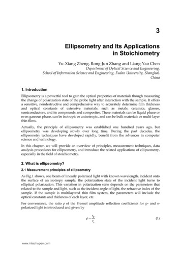
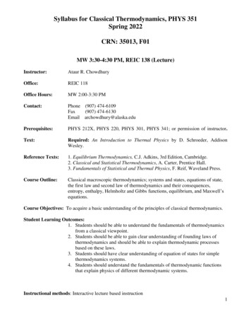
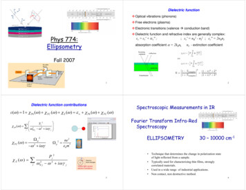
Dielectric function Optical vibrations (phonons) Free electrons (plasma) Electronic transitions (valence Æ conduction band) Dielectric function and refractive index are generally complex:Phys 774:Ellipsometryεr εr' iεr'' ;; εr' nR2 - nI2 ; εr'' 2nRnIabsorption coefficient α 2k0nInI - extinction coefficientFall 20071Dielectric function contributionsε (ω ) 1 χ Ph (ω ) χ FC (ω ) χ E (ω ) ε χ Ph (ω ) χ FC (ω ) S j2χ ph (ω ) 2 ωTO ω 2 iωγ jjj χ FC (ω ) Ω p2 ω 2 iωγχ E (ω ) ωj2ELLIPSOMETRYne 2 ε 0 m* Pj 220jSpectroscopic Measurements in IRFourier Transform Infra-RedSpectroscopy Ωp2 ω 2 iω γ j 330 – 10000 cm-1Technique that determines the change in polarization stateof light reflected from a sample.Typically used for characterizing thin films, stronglycorrelated materials.Used in a wide range of industrial applications.Non contact, non destructive method.4
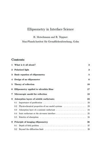
Ellipsometry and Grating SpectrometersPrinciples and goals of Ellipsometryρ rprsPMT orPhotodiodeφ0 variableDisadvantages:Cannot use lenses due toDepolarization effectsNormalization is difficultdue to complicatedresponse of the gratingEllipsometry:Linear polarized light is incident on the sample under an angleφ0 and polarization of the reflected light is measured.56Ellipsometry and Grating SpectrometersSpectroscopic EllipsometerSOPRA GESP5Disadvantages here ?PMT orPhotodiodeResolution decreases if wecannot illuminate all grovesof the grating7 SOPRA variable angle spectroscopic ellipsometer GESP58
FT-IR EllipsometryAdvantages:1. Multiplexing2. Throughput (no slits needed)Types of Ellipsometer Ellipsometers may be single wavelength orspectroscopic They may operate as rotating element or asnulling ellipsometers They may be single point or imagingIR-bolometer910Plane of IncidenceFresnel’s Equations Plane of incidence of light is the plane containing the normal to thesample surface and the incident direction of light. The s-plane is perpendicular to the plane of incidence. The p-plane is parallel to the plane of incidence. Fresnel’s equationsgive the complexamplitude of thereflected lightPolarization P I y Ixry n1cosφ n 2 cosφ ry eiδ yn1cosφ n 2 cosφφrx n 2 cosφ n1cosφ rx eiδ xn 2 cosφ n1cosφφyφxI y IxϕJones Formalism cos α E linear E0 sin α 1 E Jones circular E0 i Optical elements (polarizers, mirrors, etc)Jones11 J11 J12 J Jones J 21 J 22 Ex J11 J12 E0 x E y J 21 J 22 E0 y 12
Ellipsometric EquationsWhat does an ellipsometer measure? The polarization change of light reflected from a sample interms of two parameters and Ψ These values are related to the ratio of the Fresnel reflectioncoefficients for p- and s- polarized light 1 ρ 1 ρ ε sin 2 φ0 sin φ0 tan 2 φ0 ρ rprs tan Ψ ei φ0 variable, tanΨ rp, δ p δsrpε is a function of frequency (energy)rsrsin real experiment we need to connectρ with the polarizer angles of the instrumentusing, e.g., Jones matricesPseudo-dielectric function, which coincides with“dielectric function” for uniform and isotropic bulk materialsAnisotropy can be measured directly by changingφ0 This ratio is complex tanΨ measures the ratio of the modulus of the amplitudereflection ratio The phase difference between p- and s-polarised reflectedlight is given by 13What can ellipsometry tell us aboutsamples? Taken on there own values of and Ψ tell us littleabout a sample. We take the measured values of and Ψ, typicallyas a function of wavelength and angle of incidence(Variable Angle Spectroscopic Ellipsometry). An optical model is then built using as muchinformation about the sample as possibleWhat cannot be directly determinedfrom ellipsometry measurement?Multilayer sample structure (it is not a forensic tool) tan Ψ ei 1514Select the modeland Optical FunctionsThe optical model will generally consist of The thickness of a film or layer The complex refractive indexN nr – iniSometimes, the complex dielectric constant ε εr – iεiis given, whereN2 ε For a Mixture of materials use the Effective MediumApproximation16
Extracting data in ellipsometry Acquire data of spectral range and angleof incidence required Build an optical model that describessample structure. Generate theoretical data from opticalmodel. Compare experimental and theoreticaldata Vary model parameters, such as filmthickness, until a “best fit” toexperimental data is obtained.Regression Regression algorithms are used to vary unknown parametersand minimize the difference between model and experimentaldata. The Levenberg-Marquardt algorithm is the most widely used.measurecos and tanΨconstruct opticalmodelThe algorithm seeks to minimise the functionχ compare dataand model{122 (tanψ measured tanψ model ) (cos measured cos model )2N M Nwhere N is the number of data points at the differentmeasured wavelengths and M the number of modelparameters.Global minimum.print model data17Fit the dataRegression Analysis18Advantages of Ellipsometry The data are then compared with the data generatedfrom the theoretical model. Unknown parameters in the optical model, such asfilm thickness or optical constants, are varied to tryto produce a “best fit” to experimental data. Regression algorithms, such as Levenberg-Marquadt,are used to vary unknown parameters and minimizethe difference between experimental and modelgenerated data. Physical parameters are obtained once a good fit isachieved.19 It measures the ratio of two values so is highlyaccurate and reproducible, does not need areference sample, and is not so susceptible to lightsource fluctuation Since it measures phase, it is highly sensitive tothe presence of ultra-thin films (down to submonolayer coverage). It provides two pieces of data at each wavelength.More film properties can be determined.20}
What is far-IR Ellipsometry?Some applications of Ellipsometry: Data storage:– Characterization of thin films used the manufacturing of storagemedia Display technology:– Characterisation of materials used in flat panel displays Optical coatings:– Study of coatings on filters, beam splitters and other opticalcomponents. Biology / Chemistry:– Study of organic semiconductors, and tissue samples. In-situ measurement:– Allows real time monitoring of etching and thin film depositionprocesses.21Example of far-IR spectroscopic Ellipsometry:Hardening of the soft modes in SrTiO3 thin filmsFar-Infrared Ellipsometry is a technique which allows one to measure very accurately and with highreproducibility the complex dielectric function ε(ω) ε(ω)1 i ε(ω)2 of oxide thin films and singlecrystals. It measures the change in polarization of Infrared light upon non-normal reflection on the surfaceof a sample to be studied. To extend the Ellipsometry technique to the Far-Infrared part of theelectromagnetic spectrum, we are going to carry out these experiments at Brookhaven National Laboratory,National Synchrotron Light Source. Synchrotron light provides three orders of magnitude more brilliant 22light in the Far-Infrared as compared to conventionally available light sources, like mercury arc lamps.Another example: Sensitivity to thin filmEllipsometry of SrTiO3 thin filmsBare SiBare SiSi 1nmoxideA.A. Sirenko, et al., Nature 404, 373 (2000)2324
Problems with transparentsamplesProblems with transparentsamples The error in is proportional to cosec For transparent samples, 1800 This can be overcome by placing a retarderin front of the light source to introduce aphase shift into the light. Alternatively, a rotating compensatorellipsometer could be used2526Hafnium oxide on siliconProblems with transparentsamplesPoor fit2728
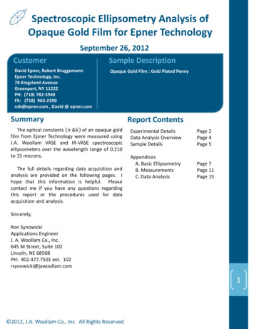
Hafnium oxide on siliconPartially oxidised sacrificial a-Si on SiCExcellent fit withparameterisation29Partially oxidised sacrificial a-Si on 4H-SiC Model (SiO2 database – aSi Forouhi)30Ellipsometry of conventionallygrown oxide on 4H-SiCεi unoxidised, etchedεi oxidised, etchedεr unoxidised, etchedεr oxidised, etched108SiO2 (1.41176 µm)ε64aSi SiO2 with density gradient (27.92 nm)2aSi (64.7 nm)012345Photon Energy eVSiC substrate3132
Grazing Incidence X-ray ReflectometryVery thin films For films of thickness about 10 nm or less,there exists a correlation between thicknessand refractive index Complementary techniques must be used tomeasure some parameters, usuallythickness. GIXR employed X-rays used in XRR have wavelengths of theorder of 1Å. Since the refractive index ofmaterials at these short wavelengths is slightly lessthan unity, x-rays are totally externally reflected atangles of incidence typically up to a few tenths ofa degree. As the incidence angle increases above thecritical angle for total reflection, x-rays penetratethe layers of the material.33Grazing Incidence X-ray Reflectometryvs. Ellipsometry At the interface between each layer,some of the radiation is reflected to thelayer above, while some is transmitted(refracted) to the layer below.The wave interference produces a seriesof fringes in the reflectivity curve.Layer densities, thickness and interfaceroughness can be determined from theEllipsometry of conventionallygrown oxide on 4H-SiC0.50Best fit using non-oxidised substrate0.90.45reflectivity curve.0.350.80.7cos ( )tan (ψ) datatan (ψ) best fitcos ( ) datacos ( ) best fit0.40tan (ψ) h (µm)3536
Ellipsometry of conventionallygrown oxide on 4H-SiC0.50Another example:Comparison of XTEM andSpectroscopic EllipsometryBest fit using etched thermal oxide as substrate0.90.45tan (ψ)0.350.80.7cos ( )tan (ψ) datatan (ψ) best fitcos ( ) datacos ( ) best length (µm)3738
Principles and goals of Ellipsometry Ellipsometry: Linear polarized light is incident on the sample under an angle φ0 and polarization of the reflected light is measured. 0 variable p s r r ρ φ 6 Ellipsometry and Grating Spectrometers PMT or Photodiode Disadvantages: Cannot use