Transcription
A ALBORG U NIVERSITYInstitute of Physics and NanotechnologyPontoppidanstræde 103 - 9220 Aalborg Øst - Telephone 96 35 92 15TITLE:EllipsometrySYNOPSIS:PROJECT PERIOD:September 1st - December 21st 2004THEME:Detection of NanostructuresPROJECT GROUP:116GROUP MEMBERS:Jesper JungJakob BorkTobias HolmgaardNiels Anker KortbekSUPERVISOR:Kjeld PedersenNUMBERS PRINTED: 7REPORT PAGE NUMBER: 70TOTAL PAGE NUMBER: 132This project concerns measurement of the refractive index of various materials and measurement of the thickness of thin films on silicon substrates by use of ellipsometry. The ellipsometer used in the experiments is the SE850 photometric rotating analyzer ellipsometer from Sentech.After an introduction to ellipsometry and aproblem description, the subjects of polarization and essential ellipsometry theory arecovered.The index of refraction for silicon, aluminum, copper and silver are modelled using the Drude-Lorentz harmonic oscillatormodel and afterwards measured by ellipsometry. The results based on the measurementsshow a tendency towards, but are not adequately close to, the table values. The materials are therefore modelled with a thin layerof oxide, and the refractive indexes are computed. This model yields good results for therefractive index of silicon and copper. Foraluminum the result is improved whereas theresult for silver is not.The thickness of a thin film of SiO2 on a substrate of silicon is measured by use of ellipsometry. The result is 22.9 nm which deviatesfrom the provided information by 6.5 %.The thickness of two thick (multiple wavelengths) thin polymer films are measured.The polymer films have been spin coated onsubstrates of silicon and the uniformities ofthe surfaces are investigated. The two polymer films are measured to be 3.32 and 4.17 µmon average with a maximum deviation fromthe mean across the surface of 3.0 % and 4.2 %respectively.
PrefaceThis project is written by group 116 at the Institute of Physics and Nanotechnology, Aalborg University, in the period between September 1st 2004 and December 21st 2004. Thetheme for the 7th semester project on Applied Physics is ”Detection of Nanostructures” under which the project ”Ellipsometry” has been chosen.The main report consists of three parts. The Preanalysis, the Ellipsometry Theory and theSimulations and Experiments. The three parts begins with a short introduction and consistsof several chapters each starting with a description of the contents. The main report treatssubjects that have direct relevance to ellipsometry and the ellipsometric measurements performed during this project.In addition to the main report several subjects are treated in appendixes which can befound after the bibliography. The appendixes treat subjects of general theory of light waves,optics and properties of materials. Also included in the appendixes are some of the moreextensive calculations and test descriptions of the performed tests.Enclosed on the inside of the back page is the project CD, containing test data, sourcecode etc. References to files on this CD e.g. Matlab programs, are written in squarebrackets containing the path and filename with extension like this: [CD 2004, matlab/polymer thickness/film thickness polymer.m]. References to other sources are written in similar manner, where the author and year of publishing refer to the bibliography, where furtherinformation about the source can be found. References to a source can be found at the endof a section, where the use of the source ends. The reference to a source might also contain apage number if necessary, e.g. [Azzam & Bashara 1977, p. 245]. A citation before a punctuation means that the reference is to the sentence only. A citation after a punctuation meansthat the reference is related to the whole paragraph.Regarding the notation throughout the report it has been decided to use [Klein & Furtak1986] as a general guideline, e.g. vectors will be boldfaced E and matrixes will be boldfacedArial A. In the cases that [Klein & Furtak 1986] does not cover the notation, the notation ofthe used source is adapted. The symbol j will be used as the imaginary unit.Aalborg University, Tuesday 21st 2004III
IVJesper JungJakob BorkTobias HolmgaardNiels Anker Kortbek
ContentsIntroduction1I Preanalysis31 Introduction to Ellipsometry52 Problem Description7II Ellipsometry Theory93 Polarization of Light3.1 Definition of Polarization . . . . . . . . . . . . . . . . . . . . . . . . . . . . . .3.2 Polarization Types . . . . . . . . . . . . . . . . . . . . . . . . . . . . . . . . . . .3.3 Definition of the ellipsometric parameters ψ and Δ . . . . . . . . . . . . . . . .111112164 Ellipsometer Systems4.1 Description of an Ellipsometer . . . . . . . . . . . . . . .4.2 Different Ellipsometer Configurations . . . . . . . . . . .4.3 Determination of ψ and Δ with a Static Photometric RAE4.4 Description of the Sentech SE 850 Ellipsometer . . . . . .21212225295 Calculations of Physical Properties5.1 Index of Refraction . . . . . . . . . . . . . . . . . . . . . . . . . . . . . . . . . .5.2 Film Thickness . . . . . . . . . . . . . . . . . . . . . . . . . . . . . . . . . . . . .5.3 Film Thickness of a Thick Thin Film . . . . . . . . . . . . . . . . . . . . . . . .33333436III Simulations and Experiments396 Simulation of the Refractive Index of Crystals6.1 Silicon . . . . . . . . . . . . . . . . . . . . .6.2 Copper . . . . . . . . . . . . . . . . . . . .6.3 Aluminum . . . . . . . . . . . . . . . . . .6.4 Silver . . . . . . . . . . . . . . . . . . . . .41424344467 Discussion of Crystal Measurements.49V
CONTENTS7.17.27.37.47.5Silicon . . .Copper . .AluminumSilver . . .Summary .52545556578 Discussion of SiO2 Film Measurements8.1 Film Thickness . . . . . . . . . . . . . . . . . . . . . . . . . . . . . . . . . . . . .59599 Discussion of Polymer Film Measurements9.1 Film Thickness . . . . . . . . . . . . . . . . . . . . . . . . . . . . . . . . . . . . .9.2 Uniformity of Film Thickness . . . . . . . . . . . . . . . . . . . . . . . . . . . .9.3 Summary . . . . . . . . . . . . . . . . . . . . . . . . . . . . . . . . . . . . . . . .63636466Conclusion67Bibliography69AppendixA The Electromagnetic Wave Model of Light71B Fresnel Reflection and Transmission Coefficients77C Three Phase Optical System85D The Jones Formalism91E Correlation between the Stokes Parameters and ψ and Δ97F Index of Refraction101G Index of Refraction and Band Structures of Crystals109H Test Report of Refractive Index of Crystals119ITest Report of the Thickness of an SiO2 Film on Si123JTest Report of the Thickness of a Polymer Film on Si127CD/datasheets/matlab/mapleVI
IntroductionOptical measurement techniques in development and production are of great interest sincethese techniques are normally non-invasive. Using these techniques involves no physicalcontact with the surface and does not normally destruct the surface. This is a notable property of a measurement technique on nanoscale. Only surfaces that are sensitive to bleachingcan be subject to damage by optical measurements. There are several optical measurementtechniques based on the reflection or transmission of light from a surface, among these areinterferometry, reflectometry and ellipsometry. There are three different types of ellipsometry, namely scattering, transmission and reflection ellipsometry. This project concerns reflection ellipsometry only.Ellipsometry normally requires some computer power to get results and therefore, thetechnique has only recently become widely used, although it has been known and usedsince Paul Drude proposed it over 115 years ago. [Poksinski 2003, p. 1]Ellipsometry can be used to measure any physical property of an optical system that willinduce a change in polarization state of the incident light wave. This makes ellipsometry avery versatile technology that is useful in many different applications.One possible application is in the semiconductor industry. This industry often deals witha thin layer of SiO2 on a silicon wafer used throughout production. In order to keep trackand effectively control the thickness of this film, process engineers can use ellipsometryto measure the film thickness of selected sample wafers. Ellipsometry is known for thehigh accuracy when measuring very thin film, with a thickness in the Ångström scale orbelow. When measuring thicker films the technique becomes more complex and requiresmore calculations.Other possible applications of ellipsometry are determination of the refractive index, thesurface roughness or the uniformity of a sample and more. [Jawoollam 2004]This project addresses the issue of ellipsometry as a way of determining physical properties of an optical system. A Sentech SE 850 ellipsometer has been put at disposal for thegroup in order to perform test of various samples. This leads to the goal of the projectThe goal of this project is to determine the complex index of refraction of several materials and thethickness of films by ellipsometric measurements.1
Part IPreanalysisThe first part contains a short introduction to ellipsometry and the different terms used in connectionwith the technique. All important terms mentioned in this part will be described in depth later inthe report. After this introduction, a problem description will line up the purposes and more specificgoals within this project.3
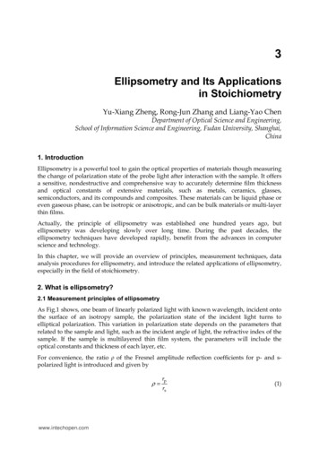
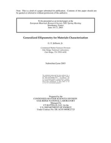
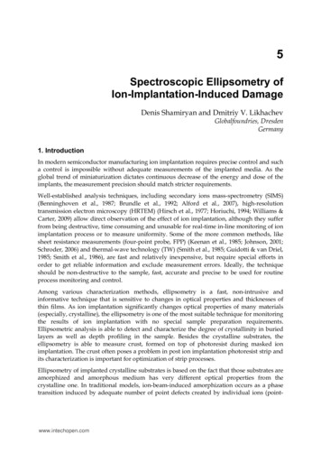
1Introduction to EllipsometryEllipsometry is generally a non-invasive, non-destructive measurement technique to obtainoptical properties of a sample material by means of the reflected light waves. The techniquemeasures a relative change in polarization and is therefore not dependent on absolute intensity as long as the absolute intensity is sufficient. This makes ellipsometric measurementvery precise and reproducible.Ellipsometry uses the fact that linearly polarized light at an oblique incidence to a surfacechanges polarization state when it is reflected. It becomes elliptically polarized, thereby thename ”ellipsometry”. In some cases elliptically polarized light is used as the incident lightwave. The idea of ellipsometry is shown in general in Figure 1.1.Linearly polarizedlight waveEinπ-planeσ-planePlaneπ-planekinof incidencekoutσ-planeElliptically polarizedlight waveEoutSurfaceFigure 1.1: The general principle in ellipsometry. [Jawoollam 2004]When a monochromatic, plane light wave is directed at a surface at oblique incidence,the plane of incidence is defined as a plane perpendicular to the surface and containing thevector which points in the direction of propagation of the light wave. This vector is calledthe wavevector kin . Perpendicular to kin are the two mutually perpendicular vectors for theelectric field E and the magnetic field B of the light wave. The E-vector is chosen as thevector defining the polarization of the light wave and is therefore the only one shown inFigure 1.1. The E-vector is decomposed into two components, which are mutually perpendicular and perpendicular to kin . The two components of E are respectively parallel andperpendicular to the plane of incidence as seen in Figure 1.1. The vectors are named fromtheir German names, ”Parallel” and ”Senkrecht”, and are from this given the correspondingGreek letters π and σ, respectively.The incident light wave is linearly polarized. Polarization will be described in depthlater, but for now the π- and σ-component of E can be seen as oscillating with an amplitude5
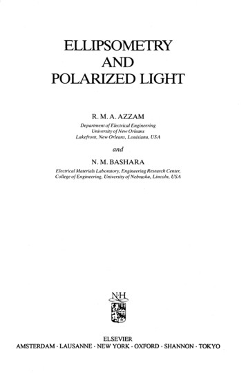
CHAPTER 1. INTRODUCTION TO ELLIPSOMETRYand mutual phase causing the endpoint of E to move in a straight line in the plane of theπ- and σ-components. When the light wave reflects off the surface, the polarization changesto elliptical polarization. This means that the amplitude and mutual phase of the π- andσ-component of E are changed causing the endpoint of E to move in an ellipse.The form of the ellipse can be measured by a detector and data processing can relatethis to the ellipsometric parameters ψ and Δ. The ellipsometric parameters can be relatedto the reflection coefficients of the light polarized parallel and perpendicular to the plane ofincidence ρπ and ρσ , respectively. The relation is the basic equation in ellipsometry and isgiven by the complex ratio ρ of the two reflection coefficientsρ ρπ tan(ψ)e jΔρσ(1.1)The ellipsometric parameters ψ and Δ are given by a measurement with an ellipsometer andthe two reflection coefficients are functions of the complex refractive index of the material.Ellipsometry is often used to measure the thickness of thin films on top of a substrate.A simplified model of this is shown in Figure 1.2 where an incident light wave is reflectedoff and transmitted through the surface of a thin film. If the refractive indexes of the filmand the substrate are known, it is possible to calculate the thickness d of the thin film byellipsometry. This application of ellipsometry is widely used to investigate materials andsurfaces.EinEoutAirThin film}dSubstrateFigure 1.2: Illustration of a thin film on top of a crystal.6
Problem Description2There are two overall objectives in this project. These are to determine the refractive indexof various materials and to determine the thickness of various films by ellipsometry. Thematerials at hand in this project for measuring the index of refraction are silicon, aluminum,copper and silver. The materials with a film on a substrate are silicon with a silicon dioxidefilm and silicon with a polymer film.The following requirements are to be met in this project.1. Theoretical(a) Modelling of the optical system under investigation in order to enable calculationof refractive index and film thickness.2. Simulation(a) Simulation of the refractive index of silicon, aluminum, copper and silver.3. Experiments(a) Refractive Index — Use ellipsometry to measure the refractive index of silicon,aluminum, copper and silver.(b) Thickness of thin SiO2 film — Measurement of the thickness of a thin film ofsilicon dioxide on a silicon wafer.(c) Thickness and uniformity of polymer film — Measurement of the thickness oftwo optically thick polymer films on substrates of silicon. Furthermore, severalmeasurements of the thickness of the polymers should be performed in order toillustrate the uniformity of the surfaces.All materials except the SiO2 and polymer films are provided by the Institute of Physicsand Nanotechnology at Aalborg University. The SiO2 film sample is a test wafer from Sentech. The test wafer has a known film thickness. Two polymer films are imposed on silicon wafers by NanoNord A/S. The polymers are spin coated on the wafers and afterwardsbaked at high temperature as prescribed by the manufacturer of the polymer. The polymer is manufactured by HD MicroSystems and is called PI-5878G. The two samples differonly in the angular speed of the spin coating which should yield different thicknesses of thepolymer. Estimates from NanoNord suggest that the polymers are 2 and 5 µm, but theseestimates are very loose.7
Part IIEllipsometry TheoryThis part contains three chapters. The first concerns polarization of light, where elliptically polarizedlight is of special interest. Also treated in this chapter is the correlation between the ellipsometricparameters and the Fresnel reflection coefficients. The second chapter concerns ellipsometer systems.In this chapter a description of different ellipsometer configurations is given. The ellipsometer usedin the tests is also described in this chapter. The last chapter in this part concerns calculation ofrefractive index and film thickness by use of measured ellipsometric parameters.9
Polarization of Light3This chapter describes the polarization of light. Three types of polarization will be introduced. Theseare linearly, circularly and elliptically polarized light. The descriptions of these polarization types willbe limited to treat monochromatic plane waves only. Apart from this, a description of unpolarizedlight will be given. Finally, the ellipsometric parameters ψ and Δ will be introduced.This chapter is mainly based on [Klein & Furtak 1986, pp. 585-596] and the definitions derivedin Appendix A.3.1Definition of PolarizationFrom the description of monochromatic plane light waves, treated in Appendix A, it can beseen that light consists of an electric field E and a magnetic field B. The connection betweenthese and the direction of propagation is given by (A.28) and rewritten hereB k Eω(3.1)where the direction of propagation is the direction of k. It is seen that electromagnetic wavesare transverse waves, i.e. E and B are mutually perpendicular and perpendicular to k. Asa consequence, E can point in any direction perpendicular to k. Thus E has two degrees offreedom, i.e. it is ”free” to move in a 2-dimensional coordinate system. This can be seen inopposition to longitudinal waves, which are bound to point in the direction of propagation.This extra degree of freedom implies the existence of different polarization states, which inthe following will be divided into some basic types. But first, some general definitions willbe stated.The polarization direction of light is defined as the direction of E. When E is known, Bcan readily be deduced, direct or indirect from Maxwell’s equations, e.g. from (3.1).In the following, a right-handed system of coordinates is used, where the z-axis is definedas the direction of propagation. Thus, the E-field can be described as a linear combinationof an x- and y-componentE(z,t) Ex x̂ Ey ŷ(3.2)Ex (z,t) Ax cos(ωt kz φx )(3.3a)Ey (z,t) Ay cos(ωt kz φy )(3.3b)whereas described in (A.24).11
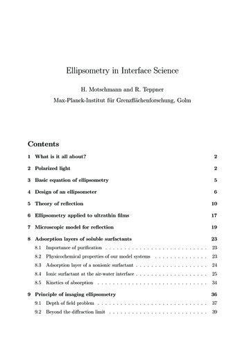
CHAPTER 3. POLARIZATION OF LIGHTIf only the polarization state is of interest, the temporal and spatial dependencies can beomitted. Thus, by using the Jones formalism, which is described in Appendix D, (3.3) canbe expressed by a Jones vector ExAx e jφxE (3.4)EyAy e jφyas described in (D.6) and (D.7). (3.4) entirely describes the polarization of light. Whether thelight is described using the Jones formalism (3.4) or with the temporal and spatial information included (3.3), the essential parameters are the relative phase φ defined asφ φy φx(3.5)and the relative amplitude, which is a relation between Ax and Ay .3.2 Polarization TypesIn the following some basic polarization types will be defined.3.2.1Linearly Polarized LightLinearly polarized (LP) light1 is the most straightforward example of polarized light. Lightis linearly polarized when E(z) and E(t) oscillates on a bounded straight line projected inthe xy-plane, with the center at (0, 0). This occurs whenφ pπ , for p {0, 1, 2, · · · }(3.6)which implyEy AyExAx(3.7)Hence, Ey is a linear function of Ex , and vice versa, as both Ax and Ay are constants. An illustration of the projection of LP light in the xy-plane can be found in Figure 3.1(a). A depictionof E with respect to z, where the time is held constant, can be found in Figure 3.1(b).NoteThe requirement to the phase stated in (3.6) is only requisite when both Ax 0 and Ay 0. IfAx 0 or Ay 0, the light is linearly polarized.3.2.2Circularly Polarized LightLight is circularly polarized (CP) when E, with respect to t as well as z, defines a circleprojected in the xy-plane. Thus, the following phase-relation must holdφ 1 Linearly12π pπ , for p {0, 1, 2, · · · }2polarized light is also denoted plane polarized light.(3.8)
3.2. POLARIZATION TYPESyAyyAyzAx xx64200Ax(a) Depiction of E in the xy-plane.(b) Illustration of E(z).Figure 3.1: Illustration of linearly polarized light for φ π and Ax Ay . Exand Ey are illustrated by the dark and light grey curve, whereas the totalelectric field is illustrated by the black curve.and the following amplitude relation must be fulfilledAx Ay 0(3.9a)Ax Ay 0(3.9b)orbut the latter is not taken into account in the following, as (3.9b) can be expressed using(3.9a) with a extra phase difference of π. It is seen that the direction of rotation projected inthe xy-plane depends of φ. The two directions are denoted RCP (Right Circularly Polarized)2and LCP (Left Circularly Polarized) respectively. LCP occurs when E rotates clockwise withrespect to z when viewed along the negative direction of the z-axis. This can be seen in Figure 3.2(a). A spatial depiction of LCP light with respect to z can be found in Figure 3.2(b).When LCP light is described with respect to t, the rotation will consequently be in the counterclockwise direction. LCP occurs when φ π/2 2pπ, where p {0, 1, 2, · · · }. Naturallythe direction of rotation of RCP is opposite to LCP both with respect to z and t. RCP occurwhen φ π/2 2pπ, where p {0, 1, 2, · · · }.The fact that E defines a circle in the xy-plane when (3.8) and (3.9) are met, can be seenfrom the following. If φ π/2, and Ax Ay A, then (3.3) can be expressed asEx A cos(ωt kz φx )πEy A cos(ωt kz φx )2 A sin(ωt kz φx )(3.10a)(3.10b)2 Thename RCP origins from the appearance of a normal screw, where the spiral groove has the same shapeas RCP light with respect to z if the screw is placed in the z-axis [Klein & Furtak 1986, p. 588].13
CHAPTER 3. POLARIZATION OF LIGHTyAyzy1AyAy x0Ax1x(a) Depiction of E(z) in the xy-plane.(b) Illustration of E(z).Figure 3.2: Illustration of LCP light (φ π/2) and Ax Ay . Ex and Ey areillustrated by the dark and light grey curve, whereas the total electric fieldare illustrated by the black curve.Adding the squared of (3.10a) to the squared of (3.10b) yieldsEx2 Ey2 (A cos(ωt kz φx ))2 ( A sin(ωt kz φx ))2 A2 (cos2 (ωt kz φx ) sin2 (ωt kz φx )) A2(3.11)where it is observed that (3.11) is the representation of a circle with the center in (0, 0).3.2.3Elliptically Polarized LightIf E with respect to z and t describes an ellipse projected in the xy-plane, the light is denotedelliptically polarized (EP). First, a simple description of EP light is considered.Description of Elliptically Polarized Light Starting From Circularly Polarized LightStarting from the description of CP light, the restriction to the phase given by (3.8) is kept,whereas the amplitude relation given by (3.9) is discarded. This is done in order to allowAx Ay . Ax and Ay must however still be nonzero. Similarly as in (3.11) it is seen thatEx2 Ey2 1A2x A2y(3.12)which is the description of an ellipse with the major and minor axis along the x- and y-axis.14
3.2. POLARIZATION TYPESGeneral description of Elliptically Polarized LightIn general, no restrictions to the relation between the amplitudes Ax and Ay or the phasedifference φ exist for EP light. The general case of EP light can then be stated using (3.3) asEx Ax cos(ωt kz)(3.13a)Ey Ay cos(ωt kz φ)(3.13b)which can be written asEx cos(ωt kz)AxEy cos(ωt kz) cos(φ) sin(ωt kz) sin(φ)Ay(3.14a)(3.14b)Multiplying (3.14a) with cos(φ) and subtracting the result from (3.14b) yieldsE y Ex cos(φ) sin(ωt kz) sin(φ)Ay Ax sin(φ) 1 cos2 (ωt kz)(3.15)(3.16)Squaring this, results inEy2 Ex2Ex Ey 2 cos2 (φ) 2cos(φ) [1 cos2 (ωt kz)] sin2 (φ)2Ay AxAx Ay(3.17)Substituting the squared of (3.14a) into (3.17) yields 2 Ey2 Ex2Ex EyEx2 cos (φ) 2cos(φ) 1 sin2 (φ)A2y A2xAx AyAx(3.18)orEy2 Ex2Ex Ey 2 2cos(φ) cos2 (φ) 12Ay AxAx Ay(3.19)which defines an ellipse in the xy-plane. It is seen from (3.19) that if φ pπ, forp {· · · , 2, 1, 0, 1, 2, · · ·}, thenEy (( 1) p )AyExAx(3.20)which, as expected results in the definition of LP light. Similarly if φ pπ/2, thenEy2 Ex2 1A2y A2x(3.21)which is EP light with the major axis along the x- or y-axis; or if Ax Ay it is CP light. Thus,LP and CP light are both special cases of EP light. It is clear that the ellipse described inthe xy-plane will be inscribed in a rectangle given by Ax and Ay . An illustration of EP lightprojected in the xy-plane can be seen in Figure 3.3.15
CHAPTER 3. POLARIZATION OF LIGHTyAxAyzxFigure 3.3: Illustration of elliptically polarized light.3.2.4Unpolarized LightUnpolarized light is the term used for light that is not polarized in any defined pattern asthe ones stated above. For unpolarized light, the electric field vector fluctuates in a randompattern. If E is divided into components described as in (3.2), Ex and Ey will be incoherent.That is, the phase relation of the components will be random. Furthermore, as the fieldvector fluctuates randomly, the mean value of the magnitude of the field will be the same inall directions perpendicular to the direction of propagation. Thus A2x A2y .3.3 Definition of the ellipsometric parameters ψ and Δψ and Δ angles will in the following be defined as quantities describing the reflected light,when linearly polarized light is incident on a surface. A depiction of the orientations of thecoordinate systems for the incident and the reflected E-field in relation to the surface can beseen in Figure 3.4. Using the definition of the Jones vector, a new term χ is defined as theratio between the components in the Jones vector, namelyχ EyEx(3.22)The surface can be viewed as a system with the incident E-field Ei as the input and thereflected E-field Eo as the output. This is illustrated in Figure 3.5 in terms of χ. The term ofinterest is the relation describing the optical system S, which is given as χi /χo , thusχi χo16EiyEixEoyEox Eiy EoxEix Eoy(3.23)
3.3. DEFINITION OF THE ELLIPSOMETRIC PARAMETERS ψ AND ΔzoEoyoxoEtziEixiyiSurfaceFigure 3.4: Illustration showing the orientation of the coordinate systemsrelative to the sample surface. Ei is the incident or input E-field, Eo is thereflected or output E-field and Et is the transmitted E-field. y is parallelwith the surface.χiχoSFigure 3.5: Input χi and output χo to an optical system S.Rewriting this expression using the Jones vector, (3.4) yieldsAiy e jφiy Aox e jφoxχi χo Aix e jφix Aoy e jφoyAiy j(φiy φix ) Aox j(φox φoy )ee AixAoy(3.24)(3.25)If the incident light is linearly polarized with φi 0 and Aix Aiy , then (3.25) is given asχiAox j(φox φoy ) eχo Aoy(3.26)which only contains information for the elliptically polarized reflected light. For the reflected light, the parameter ψ is defined in order to satisfy the followingtan ψ AoxAoy(3.27)This is illustrated in Figure 3.6.17
CHAPTER 3. POLARIZATION OF LIGHTyoAxoψzoAyoxoFigure 3.6: Illustration of ψ, which is defined for reflected elliptically polarized light.Furthermore, the parameter Δ is defined asΔ φox φoy(3.28)Using (3.27) and (3.28), (3.26) can be expressed asχi tan(ψ)e jΔχo(3.29)which is a general ellipsometer equation [Azzam & Bashara 1977, p. 259].3.3.1Connecting ψ and Δ to ρπ and ρσThe Fresnel reflection coefficients are introduced in Appendix B as the reflected amountof the E-field in proportion to the incident amount. This is viewed either parallel (π) orperpendicular (σ) to the plane of incidence asEoπEiπEoσρσ Eiσρπ (3.30a)(3.30b)where all E-vectors are Jones vectors. By fixing the xy-coordinate system to the samplesurface so that x is parallel to the plane of incidence and y is perpendicular to the plane of18
3.3. DEFINITION OF THE ELLIPSOMETRIC PARAMETERS ψ AND Δincidence, (3.23) can be rewritten toEiy Eoxχi χo Eix Eoy Eiσ Eoπ Eiπ Eoσ Eoπ Eiπ Eoσ Eiσ ρπρσ(3.31)(3.32)(3.33)(3.34)Inserting this expression into (3.29) yieldsρπ tan(ψ)e jΔρσ(3.35)which correlates the ellipsometric parameters to the Fresnel reflection coefficient of a surface. This correlation is utilized throughout the rest of the report to derive expressions fore.g. the refractive index of a material as a function of ψ and Δ.19
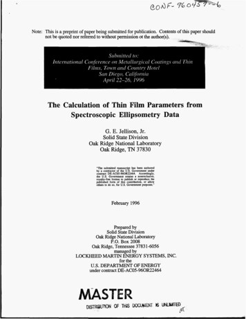
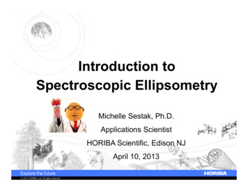
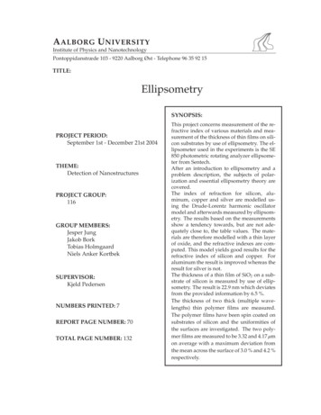
4Ellipsometer SystemsThis chapter concerns the operational principle of ellipsometers. First a general introduction to ellipsometers is given which explains the different components encountered in an ellipsometer. After thisintroduction to ellipsometers, two different ellipsometer configurations are described, namely the nulland the photometric ellipsometer. After this, the problem of measuring the ellipsometric parametersψ and Δ with a photometric rotating analyzer ellipsometer is treated. Finally a description of theSentech SE 850 ellipsometer used in this project is given.4.1Description of an EllipsometerEllipsometry is generally defined as the task of measuring the state of polarization of a wave.In the case of an optical system the wave of interest would be a light wave. Although the polarization state of a light wave itself can be of interest, in reflection ellipsometry the changein polarization is the essential issue. This change in polarization as the light is reflected ata surface boundary is caused by difference in Fresnel reflection coefficients as described inAppendix B. These coefficients are different for π and σ polarized light. A general ellipsometer configuration is depicted in Figure 4.1. As can be seen from the figure an ellipsometerσσαCπSπαAαPCAPDLFigure 4.1: Illustration of a general ellipsometer setup. Light is emittedfrom the source L, passes through the linear polarizer P and the compensator C before it is reflected at the surface boundary S. After reflectionthe light again passes a linear polarizer denoted the analyzer A before itreaches the detector D. [Azzam & Bashara 1977, p. 159]generally consists of six parts:The light source which emits circularly or unpolarized light. This can be either a laser orsome type of lamp. A laser has the advantage of emitting very intense and well collimated light which produces a very small spot size on the sample. It is however notpossible to use a laser to perform spectroscopic measurements as the laser contains21
CHAPTER 4. ELLIPSOMETER SYSTEMSonly one wavelength. However
Ellipsometry uses the fact that linearly polarized light at an oblique incidence to a surface changes polarization state when it is reflected. It becomes elliptically polarized, thereby the name ”ellipsometry”. In some cases elliptically polarized light is used as the incident light wave. The idea of ellipsometry is shown in general in .File Size: 1MB