Transcription
LTE RF Measurements with theR&S CMW500 according to 3GPPTS 36.521-1Application NoteProducts: R&S CMW500The 3GPP TS 36.521-1 “Radiotransmission and reception” LTE UserEquipment (UE) conformancespecification defines the measurementprocedures for LTE terminals with regardto their transmitting characteristics,receiving characteristics and performancerequirements as part of the 3G Long TermEvolution (3G LTE) standard.Jenny ChenMay 2014 – 1CM94 5eApplication NoteThis application note describes how to usethe LTE Frequency Division Duplex (FDD)and Time Division Duplex (TDD)measurement functionality provided by theR&S CMW500 wideband radiocommunication tester to perform LTE R8transmitter and receiver measurementsaccording to this test specification.
Table of ContentsTable of Contents1CM94 5e1Introduction . 41.1How to Use Save Files in the R&S CMW500 .51.2Select the Duplex Mode .52Transmitter Characteristics. 62.1Generic Call Setup for Transmitter Characteristics .62.2UE Maximum Output Power (TS 36.521, 6.2.2) .132.3Maximum Power Reduction (TS 36.521, 6.2.3) .152.4Additional Maximum Power Reduction (TS 36.521-1, 6.2.4) .172.5Configured UE Transmitted Output Power (TS 36.521, 6.2.5) .222.6Minimum Output Power (TS 36.521, 6.3.2) .242.7Transmit OFF Power (TS 36.521, 6.3.3) .262.8General ON/OFF Time Mask (TS 36.521-1, 6.3.4.1).262.9PRACH and SRS Time Mask (TS 36.521-1, 6.3.4.2) .312.10Power Control – Absolute Power Tolerance (TS 36.521, 6.3.5.1) .372.11Power Control – Relative Power Tolerance (TS 36.521, 6.3.5.2) .402.12Aggregate Power Control Tolerance (TS 36.521-1, 6.3.5.3) .472.13Frequency Error (TS 36.521, 6.5.1) .502.14Error Vector Magnitude (TS 36.521-1, 6.5.2.1) .522.15PUSCH EVM with Exclusion Period (TS 36.521-1, 6.5.2.1A) .562.16Carrier Leakage (TS 36.521-1, 6.5.2.2) .592.17In-Band Emissions for Non-Allocated RBs (TS 36.521-1, 6.5.2.3) .612.18EVM Equalizer Spectrum Flatness (TS 36.521, 6.5.2.4) .652.19Occupied Bandwidth (TS 36.521, 6.6.1) .682.20Spectrum Emission Mask (TS 36.521, 6.6.2.1).702.21Additional Spectrum Emission Mask (TS 36.521-1, 6.6.2.2) .732.22Adjacent Channel Leakage Power Ratio (TS 36.521, 6.6.2.3) .743Receiver Characteristics . 773.1Generic Test Description for Receive Tests .773.2Reference Sensitivity Level (TS 36.521-1, 7.3) .793.3Maximum Input Level (TS 36.521-1, 7.4) .803.4Adjacent Channel Selectivity (TS 36.521-1, 7.5) .833.5In-Band Blocking (TS 36.521-1, 7.6.1) .87Rohde & Schwarz LTE RF Measurements with the R&S CMW500 according to 3GPP TS 36.521-1 2
Table of Contents1CM94 5e3.6Narrow-Band Blocking (TS 36.521-1, 7.6.3) .903.7Wide band Intermodulation (TS 36.521-1, 7.8.1).924Literature. 945Additional Information . 946Ordering Information . 957Annex A . 967.1Precautions for the ON/OFF Time Mask .967.2Automatic testing with CMWRun .96Rohde & Schwarz LTE RF Measurements with the R&S CMW500 according to 3GPP TS 36.521-1 3
Application Note1 IntroductionThe R&S CMW500 signaling and measurement solution can be used to perform all thetransmitter and receiver tests specified in TS 36.521-1 for 3GPP Release-9. This documentprovides a step-by-step guide to performing Release-9 measurements according to 3GPPTS 36.521 V10.4.0, Clauses 6 and 7, using the R&S CMW500 LTE callbox. This descriptionrefers to the functionality provided with Version 3.2.50 of the R&S CMW500 firmware. Thisdocument will be updated to specify relevant changes caused by new firmware releases.Each test is explained in an example. Since each of the different measurements requires specificsettings, this application note includes a set of sample save files. The explanation in Section 1.1describes how to create and recall such files.The tests described here are limited to the ones that don’t need complicated external instruments,such as spectrum analyzers and filters. Spurious measurements, transmitter intermodulation, andout-of-band blocking tests, for example, are not covered. To see which other tests can beperformed when using such additional equipment, please always refer to the latestR&S CMW500 capability list, which can be found on the CMW customer web:https://extranet.rohde-schwarz.com1CM94 5eRohde & Schwarz LTE RF Measurements with the R&S CMW500 according to 3GPP TS 36.521-1 4
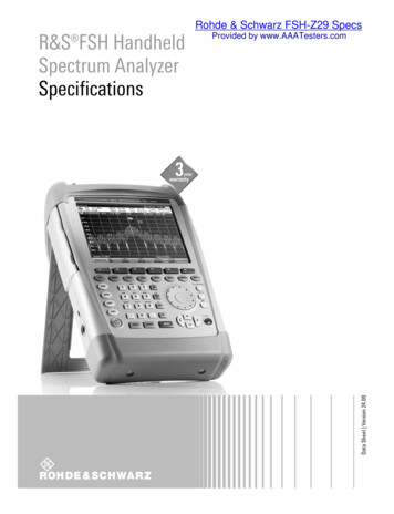
Application Note1.1 How to Use Save Files in the R&S CMW500Save files provide a convenient way to save and restore settings to satisfy the requirements ofcertain tests that you might want to perform over and over again. These files contain the currentsettings for the R&S CMW500 parameters. Save files can also be used to easily move settingsfrom one R&S CMW500 to another by storing the settings on the first device and then recallingthem on the target R&S CMW500. For your convenience, this application note comes with a setof save files for all the described tests.To use them, begin by pressing the SAVE/RCL key on the top left of the R&S CMW500’s frontpanel.Fig. 1: The SAVE/RCL key.Then follow the dialog prompts to locate your save files and select the one you want to recall.Choose the desired file by pressing the Recall button on the top right of the screen. Whenrecalling the save file, ensure that both the source and target devices are using the samefirmware.Fig. 2: The Save/Recall dialog screen.1.2 Select the Duplex ModeThe duplex mode can only be selected at Signal OFF state.For most test cases, the FDD and TDD test configurations and test steps are the same.Differences in the individual tests are specified in this document.1CM94 5eRohde & Schwarz LTE RF Measurements with the R&S CMW500 according to 3GPP TS 36.521-1 5
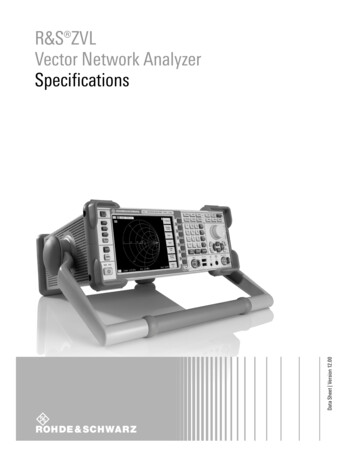
Application Note2 Transmitter Characteristics2.1 Generic Call Setup for Transmitter CharacteristicsThe following parameters are set according to these specifications:Cell set upPropagation conditionsUplink reference measurementchannels (RMCs)Configuration of PDSCH andPDCCH before measurementInitial downlink signal setupInitial uplink signal setup3GPP TS 36.508, Sub Clause 4.4.33GPP TS 36.521, Annex B.03GPP TS 36.521, Annex A.23GPP TS 36.521, Annex C.23GPP TS 36.521, Annexes C.0, C.1, andC.3.03GPP TS 36.521, Annexes H.1 and H.3.0Table 1: Sources for parameter specifications.TS 36.521, Annex C.0 describes downlink signal levels. In the R&S CMW500, the downlinksignal level should be configured so that RS EPRE is set to –85 dBm/15 kHz.TS 36.521, Annex C.1 describes the mapping of downlink physical channels and signals tophysical resources.TS 36.521, Annex C.3.0 mainly describes downlink physical channel levels.TS 36.521, Annex H.1 describes the mapping of uplink physical channels and signals to physicalresources.The resulting settings for the R&S CMW500 are as shown in Fig. 3.Fig. 3: The LTE signaling configuration screen with settings based on TS 36.521.1CM94 5eRohde & Schwarz LTE RF Measurements with the R&S CMW500 according to 3GPP TS 36.521-1 6
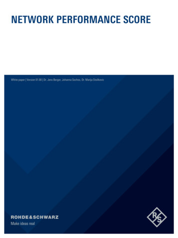
Application Note2.1.1 Rules for the Bandwidth and Frequency SettingsFrequencies and channel bandwidths are checked separately for each Evolved UMTS TerrestrialRadio Access (E-UTRA) operating band that the UE supports.Applicable channel bandwidths should follow the rules from TS 36.521, Table 5.4.2.1-1, and therequirements from the test configuration table for each test case.Most of the transmitter tests should be performed at the lowest and highest supported bandwidthas well as at the 5 MHz bandwidth. However, some tests also need to be performed at the10 MHz bandwidth. Furthermore, some tests, such as the occupied bandwidth test, are to beperformed at all bandwidths.Test frequency settings should be taken from TS36.508, Table 4.3.1. There, the low-range,middle-range and high-range channel frequency information can be found for the operating band(OB) and channel bandwidth to be tested.Most of the transmitter tests should be performed on one low-range, one middle-range and onehigh-range channel. However, some tests – such as the configured UE transmitted output powertest or the occupied bandwidth test – should only be performed on a middle-range channel.In the examples used in this application note, Operating Band 7 will be used with the 10 MHz and20 MHz bandwidths. Therefore, the corresponding frequencies/channels provided in Table 2 willneed to be set on the R&S CMW500 when testing.OBBandwidthRangeNULFrequency ofUplink [MHz]NDL710 100335020 MHzFrequencyof Downlink[MHz]262526552685263026552680Table 2: Test-frequency mapping.2.1.2 Measurement Issues Related to Expected PowerWhen using the R&S CMW500 to perform callbox measurements, the R&S CMW500 mightoccasionally display an Input overdriven or Input underdriven notice. When this happens, themeasurement is not stable. This is related to the instrument’s dynamic range setting.The figure below provides a simple illustration of the basic theory for this setting:1. The reference level represents the R&S CMW500’s maximum allowed input power. Ifthe input signal level exceeds the reference level, the instrument will display an Inputoverdriven status. Remember here that the input signal level is determined using a PEAKdetector.2. When the input signal falls into the green area, the R&S CMW500 will be able toperform the power measurement, as well as demodulate the signal.3. When the input signal level drops into the yellow area, its SNR is not good enough fordemodulation, but it is sufficient for taking power measurements.4. In the R&S CMW500 multi-evaluation interface, users should always keep the UE uplinksignal inside the demodulation area (green).5. When input signal levels are higher than the reference level or lower than the noise floor,they will not be measured correctly.1CM94 5eRohde & Schwarz LTE RF Measurements with the R&S CMW500 according to 3GPP TS 36.521-1 7
Application NoteReference LevelDemodulation areaPower measurement areaNoise floorFig. 4: Measurement levels.Consequently, the R&S CMW500’s reference-level setting is important. There are tworeference-level modes to select from. The section below states the difference between the twomodes and explains how to use them. In the R&S CMW500, the reference level is the sum ofthe expected nominal power and the margin. Only the sum of the expected nominal power andmargin is significant for the R&S CMW500. The individual values for these parameters are notrelevant, except in that sum.6. The R&S CMW500 automatically sets the reference level according to the UL powercontrol settings. When measuring PUSCH, using this setting is very simple.7. Manual mode: Here, users set the reference level themselves. Using this mode isnecessary for test cases that are related to time mask measurement for more accurateOFF power measurement.8. On the basis of the information above, it is possible to state a general rule: The inputsignal’s peak power should not exceed the reference level; furthermore, it should not fallout of the green field when using the multi-evaluation interface.1CM94 5eRohde & Schwarz LTE RF Measurements with the R&S CMW500 according to 3GPP TS 36.521-1 8
Application NoteFig. 5: Configuring the expected nominal power mode.2.1.3 General Settings Related to Multi-Evaluation MeasurementsThe measurement setting should be linked to LTE signaling for frequency and power settings, asshown in Fig. 6.Fig. 6: Selecting LTE signaling for the measurement.The Channel Type, the RB Allocation (which determines the number of resources blocks) and theModulation should be set to Auto at all times for all the tests described in this application note toavoid inconsistent configuration. Nevertheless it might be required to configure the Modulationscheme to the used TX signal Modulation scheme in case of lower TX signal power levels.1CM94 5eRohde & Schwarz LTE RF Measurements with the R&S CMW500 according to 3GPP TS 36.521-1 9
Application NoteFig. 7: Three settings that should be set to “Auto” for all of the tests described in thisapplication note.A different Measure Subframe is used for “FDD” and “TDD,” as shown in Fig. 8. The default valuefor this parameter is “0”. For FDD, the default value is OK for measurement. In TDD mode, theMeasure Subframe can only be a selection from {2,3,7,8}, because the specification requires theuplink/downlink configuration to be “1.”Fig. 8: Measure Subframe settings for FDD and TDD.2.1.4 Explanation of Demos and Manual OperationIn between each test case description in this application note, a short demo has been added toillustrate how the R&S CMW500 is used for each type of test. Therefore, these demosconcentrate on one duplex mode, one operation band, one bandwidth and one channel only. ForTDD mode, only the differences in the configuration or test steps between the FDD and TDD willbe highlighted. If not specified, the test-specific configuration and test steps are the same forTDD and FDD.In order to perform each test in strict adherence to the specification, the tests would need to berepeated for the different bandwidths and channels as explained in Section 2.1.1.To perform the tests with your own device, please be sure to transfer the described example tothe operation band that you are using in the device under test (DUT).1CM94 5eRohde & Schwarz LTE RF Measurements with the R&S CMW500 according to 3GPP TS 36.521-1 10
Application NoteDuring manual testing in the R&D stage, you always need to change some parameters (such asthe type of power control, the target power, or the RB settings) to perform your test. To make thatpossible, you can also change these parameters in the multi-evaluation interface so that youdon’t need to switch to the signaling interface. As shown in Fig. 9, if you press SignalingParameters in the right column and then select the Connection Setup button, you will be able tochange the RB Allocation and RB position (RB Pos.) as well as the Modulation Scheme for the Uplinkand Downlink. From LTE V3.0.20, the DL power, Band, Channel settings can be changed bypressing Cell Setup.Fig. 9: Changing the signaling parameters.2.1.5 General Setup for TDD modeAccording to the specification, the Uplink Downlink Configuration should be “1,” and the SpecialSubframe should be “5.” These values can be configured at LTE Signaling Config Physical CellSetup TDD, as shown in Fig. 10.Fig. 10: General configuration for TDD.1CM94 5eRohde & Schwarz LTE RF Measurements with the R&S CMW500 according to 3GPP TS 36.521-1 11
Application Note2.1.6 Advanced PRACH/Open Loop PowerFrom CMW LTE V3.0.50 onward, the Advanced PRACH /OL Power setting can be enabled underthe Uplink Power Control settings so that the user is able to change Reference Signal Power,Preamble Initial Received Target Power and other open loop related message components directly.KS510 – advance Signalling option is needed to enable these advanced settings.Below diagram displays the default settings, which are according to TS 36.508 default values.Fig. 11 Advanced Power Default SettingsTo change the Expected PRACH Preamble Power at RRCIdle mode, it is recommended to do thenecessary changes with a change of the DL RS EPRE first if needed, followed by Preamble InitialReceived Target Power.A change of the Expected OL Power can be achieved by changing PO Nominal PUSCH in eithermode, RRCConnected (through RRCReconfiguration) or RRCIdle.2.1.7 Non-Advanced Open Loop PowerIf KS510 is not present in CMW, Open Loop Nominal Power is used for configuring PRACH/OLPower. It should be the target UL total BW open loop power. The target PRACH power is 8 dBlower than the Open Loop Nominal Power. For TDD, if PRACH Configuration Index is 48 or greater,the expected PRACH power is the same as Open Loop Nominal Power, becauseDELTA PREAMBLE 8dB, according to 3GPP TS 36.321 Table 7.6-1.Fig. 12: Open Loop Nominal Power Settings2.1.8 SIB Paging and RRCReconfigurationBased on 3GPP test requirements, SIB related parameters should be changed at Cell ON state;therefore, a power cycle of the UE is required.1CM94 5eRohde & Schwarz LTE RF Measurements with the R&S CMW500 according to 3GPP TS 36.521-1 12
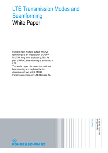
Application NoteThese SIB related parameters (Network Signalling, p-Max, SRS, PO nominal PUSCH, Preamble InitialReceived Target Power) can be changed at RRC Idle or Connected mode as well through SIBpaging or RRC Reconfiguration message initiated from the base station. However it needs to becarefully checked whether the UE is supporting the change via SIB paging orRRCReconfiguration with mobilityInfo.By default, this application note will describe the tests in the way of changing the SIB relatedparameters at Cell ON state.2.2 UE Maximum Output Power (TS 36.521, 6.2.2)This test case is for verifying that the error for the UE maximum output power does not exceedthe range prescribed by the specified nominal maximum output power and tolerance.An excessively high maximum output power could interfere with other channels or systems.Insufficient maximum power would decrease the coverage area.2.2.1 Test DescriptionFor general test conditions and settings, please refer to Section 2.1 of this application note. Thevalues to be selected for the bandwidth, frequency and RMC, along with details on the RBallocations, are defined in TS 36.521, Table 6.2.2.4.1-1. This test only uses QPSK modulationalong with an RB Allocation of 1RB or Partial RB allocation in the uplink.According to TS 36.521, Table 5.4.2.1-1, there are four bandwidth configurations for Band 7:5 MHz, 10 MHz, 15 MHz and 20 MHz. Furthermore, according to TS 36.521, Table 6.2.2.4.1-1,the maximum power only needs to be tested at the lowest bandwidth (5 MHz) and highestbandwidth. Therefore, the maximum power test only needs to be performed using the 5 MHz and20 MHz bandwidth configurations for Band 7.The test case described here will demonstrate this using Band 7 with a low-range channel and a20 MHz bandwidth.TS 36.521, Table 6.2.2.4.1-1 requires testing of a 20 MHz configuration with two different RBAllocation settings: 1RB and 18RB. Since a configuration with the settings Band 7, 20 MHz, and LowRange does satisfy Note 2 of TS 36.521-1 Table 6.2.2.3-1, the lower limit is relaxed by 1.5 dB.Also, according to TS 36.521-1, Table 6.2.2.4.1-1, Note 2, the RB position (RB Pos.) for the lowrange channel shall be low and high for 1 RB and low for 18 RB allocations.2.2.2 Test ProcedureConnect the SS to the UE antenna connectors as shown in TS 36.508, Annex A, Figure A3.Enable the LTE cell, and power on the LTE UE so that it attaches to the network. Then press theConnect button to establish the connection as shown in Fig. 13.1CM94 5eRohde & Schwarz LTE RF Measurements with the R&S CMW500 according to 3GPP TS 36.521-1 13
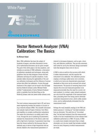
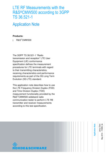
Application NoteFig. 13: Established connection.1. Configure the uplink RMC by setting # RB to 1, RB Pos/Start RB to Low, and Modulation toQPSK; set Active TPC Setup to Max. Power so that the UE output power reaches PUMAX.2. Measure the average UE output power (22.45 dBm in this example) in the error vectormagnitude (EVM) measurement screen as shown in the screenshot below.Fig. 14: Measurement results for UE maximum output power for one resource block.3. Change # RB for the RMC uplink from 1 to 18, and then press the Restart/Stop button torestart the measurement.4. Read the average UE output power (22.54 dBm in this example) results in the EVMmeasurement screen as shown in Fig. 15: .1CM94 5eRohde & Schwarz LTE RF Measurements with the R&S CMW500 according to 3GPP TS 36.521-1 14
Application NoteFig. 15: Measurement results for UE maximum output power for 18 resource blocks.2.2.3 Test RequirementsAccording to 3GPP 36.521-1, Table 6.2.2.5-1, the maximum output power must be within therange of 23 2.7 dBm.For the bands beyond 3GHz, the limits are slightly different. For Band 22, the limit is 3/-4.5 dB;for Band 42 & 43, the limit is 3/-4 dB.Note: For transmission configurations (Figure 5.4.2-1) confined within FUL low and FUL low 4 MHz or FUL high – 4 MHz and FUL high, the maximum output power requirement is relaxedby reducing the lower tolerance limit by 1.5 dB.2.3 Maximum Power Reduction (TS 36.521, 6.2.3)The number of RBs defined in TS 36.521, Table 6.2.2.3-1, is based on meeting the requirementsfor the adjacent channel leakage ratio and the maximum power reduction (MPR) due to the cubicmetric (CM).2.3.1 Test DescriptionFor UE Power Class 3, the MPR allowed for the maximum output power due to higher-ordermodulation and to the transmit bandwidth configuration (resource blocks) is specified inTS 36.521-1, Table 6.2.3.3-1.The core concept for this test is that using the higher-order modulation scheme (16QAM) and/ora large number of allocated RBs (e.g. full RB allocation) will cause a high crest factor and thuspresent a challenge in the design of power amplifiers. Therefore, the specification allows areduction of the maximum output power’s lower limit in such cases.When QPSK modulation is used with a higher number of RBs, the lower limit is relaxed by 1 dB.Also, when 16QAM is used as the UL modulation scheme, the lower limit is relaxed by 1 dB.1CM94 5eRohde & Schwarz LTE RF Measurements with the R&S CMW500 according to 3GPP TS 36.521-1 15
Application NoteWhen both conditions apply (16QAM and a higher number of RBs), the lower limit is relaxed by2 dB.For the example, a Band 7 DUT will be used. According to TS 36.521, Tables 5.4.2.1-1, and6.2.3.4.1-1, the maximum power reduction needs to be tested using the 5 MHz, 10 MHz and20 MHz bandwidth configurations. This example will concentrate on the 20 MHz bandwidth usinga mid-range channel.2.3.2 Test ProcedureConnect the SS to the UE antenna connectors as shown in TS 36.508, Annex A, Figure A3.Enable the LTE cell. After that, power on the LTE UE and wait for it to attach to the network.Then press Connect to establish the connection.The six test sets shown in Table 3 should be performed for a 20 MHz mid-range channelaccording to Note 3 in TS 36.521, Table 6.2.3.4.1-1. The example shown here will use Test Set6.#RBTest Set 1Test Set 2Test Set 3Test Set 4Test Set 5Test Set 618181818100100RB 6QAM16QAMQPSK16QAMUE OutputPowerPUMAXPUMAXPUMAXPUMAXPUMAXPUMAXTable 3: Test setup for MPR (mid range).When measuring 16QAM modulation signals, please make sure that the Modulation Scheme in themeasurement configuration is set to 16QAM or Auto.Hint: It is best to use the Auto modulation scheme setting so that you do not need to confirm thisparameter yourself. That makes it easier to perform the test.Fig. 16: Setting the modulation scheme.1CM94 5eRohde & Schwarz LTE RF Measurements with the R&S CMW500 according to 3GPP TS 36.521-1 16
Application NoteTest Set 6:1. Set the RMC uplink # RB to 100, RB Pos/Start RB to Low, and Modulation to 16QAM; setActive TPC setup to Max Power until the UE output power reaches PUMAX.2. Measure the average UE output power (21.48 dBm in this example). Configure thesettings that are marked red in Fig. 17.Fig. 17: Settings for Test Set 6.2.3.3 Test RequirementsThe maximum output power shall be within the range prescribed by the nominal maximum outputpower and tolerance in TS 36.521-1, Table 6.2.3.5-1. For Band 7 and the example above, this is23 dBm 2.7 dB/–4.7 dBE-UTRABandClass 3(dBm)723QPSK, fullRB allocationtol. (dB) 2.7 / –3.716QAM, partialRB allocationtol. (dB) 2.7 / –3.716QAM, full RBallocation tol.(dB) 2.7 / –4.7Table 4: Test requirements for the UE power class (source: TS 36.521-1, Table 6.2.3.5-1).2.4 Additional Maximum Power Reduction (TS 36.521-1,6.2.4)Additional ACLR and spectrum emission requirements can be signaled by the network to indicatethat the UE must also meet additional requirements in a specific deployment scenario. To meetthese additional requirements, additional maximum power reduction (A-MPR) is allowed for theoutput power as specified in TS 36.521-1, Table 6.2.2.3-1. Unless stated otherwise, an A-MPR of0 dB shall be used.1CM94 5eRohde & Schwarz LTE RF Measurements with the R&S CMW500 according to 3GPP TS 36.521-1 17
Application Note2.4.1 Test DescriptionThe network signal (NS) value, which the cell broadcasts from SIB2, is a key parameter for thistest item. If, for example, a Band-1 UE detects that the additional spectrum emission informationelement equals NS 05 from SIB2, it knows that it should meet the additional requirement ofspurious emissions and maximum power reduction according to TS 36.521-1, Table 6.2.4.3-1.The network signal value parameter can be set in the R&S CMW500 in the LTE Signalingconfiguration menu. By default, this parameter is set to NS 01 as shown in Fig. 18. The NS 01setting means that no additional spectrum or additional max power reduction is used. The defaultvalue NS 01 is also the setting that is required for the maximum power test and for the MPR testdescribed above.Fig. 18: Additional spectrum emission.NS has a fixed relationship with the operating band, the channel bandwidth, and the RBallocation. Detailed information on this is provided in TS 36.521, Table 6.2.4.3-1, while Tables6.2.4.3-2, 6.2.4.3-3 and 6.2.4.3-4 mainly describe detailed requirements for NS 07, NS 10, andNS 04.2.4.2 Test ProcedureThe example for A-MPR will use a Band-1 UE, because no A-MPR requirements apply for Band7. According to TS 36.521, Table 6.2.4.3-1, only NS 05 applies for Band 1, so this setting is usedfor the example.Different tables describe different RMC, RB position, frequency and bandwidth settings. Table 5shows the relationship between NS and the test configuration table.1CM94 5eRohde & Schwarz LTE RF Measurements with the R&S CMW500 according to 3GPP TS 36.521-1 18
Application Note1234Additional spectrumemissionNS 03NS 04NS 05NS 065NS 076789NS 08NS 09NS 10NS 11Test configuration table inTS .6.2.2.1E-UTRA Band2,4,10,23,25,35,3641112, 13, 14, 171319212023Table 5: The relationship between the network signal (NS) value and the test configurationtable in TS 36.521-1.Change the Additional Spectrum Emission setting on the R&S CMW500 from NS 01 to NS 05 asshown in Fig. 19 at Cell ON state.Fig. 19: Additional spectrum emission setting for NS 05.TS 36.521-1, Table 6.2.4.4.1-3 defines the test bandwidth settings, frequency settings and RMCsettings for NS 05.For NS 05, this test should apply to 5 MHz, 10 MHz, 15 MHz and 20 MHz. The frequency shouldbe low range, and a middle-range channel should be used. This demo uses a middle-rangechannel and a 10 MHz bandwidth.The RMC, RB position (according to Table TS 36.521-1, 6.2.4.4.1-3) and the output powerconditions are listed in Table 6 for the 10 MHz channel bandwidth. In the example, configurationIDs 3 and 6 are used. Configuration IDs are used to combine the test settings and testrequirements. As a result, you only need to check the corresponding configuration ID that youhave configured.1CM94 5eRohde & Schwarz LTE RF Measurements with the R&S CMW500 according to 3GPP TS 36.521-1 19
Application Note#RBRB Pos/StartRBModulationUE OutputPower112485050Low & HighLow & HighLow & XPUMAXConfigurationID34567Table 6: Settings for the 10 MHz bandwidth.Connect the SS to the UE antenna connectors as shown in TS 36.508, Annex A, Figure A3.Enable the LTE cell. Set the downlink frequency to a frequency such as 2140 MHz to make surethat the test is being performed on a middle-range channel. Then power on the LTE UE so that itattaches to the network, and press Connect to establish the connection.Configuration ID 3:1. Set the Uplink RMC setting # RB to 1, RB Pos./Start RB to Low, and Modulation to QPSK;set Active TPC Setup to Max. Power so that the UE output power reaches PUMAX.2. Measure the average UE output power (21.78 dBm in this example) in the tabular resultscreen as shown in Fig. 20.Fig. 20: Measurement of the average TX power for Configuration ID 3.Configuration ID 6:3. Set # RB to 50, RB Pos./Start RB to Low, and Modulation to QPSK; set Active TPC Setup toMax. Power until the UE output power reaches PUMAX.4. Measure the average UE output power (19.03 dBm in this example) as shown in Fig. 21.1CM94 5eRohde & Schwarz LTE RF Measurements with the R&S CMW500 according to 3GPP TS 36.521-1 20
Application NoteFig
This document provides a step-by-step guide to performing Release-9 measurements according to 3GPP TS 36.521 V10.4.0, Clauses 6 and 7, using the R&S CMW500 LTE callbox. This description . Table 2: Test-frequency mapping. 2.1.2 Measurement Issues Related to Expected Power When using the R&S CMW500 to perform callbox measurements, the R&S .