Transcription
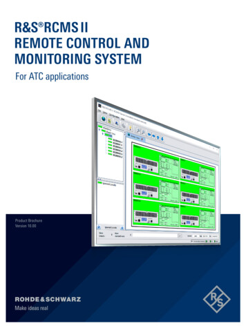
R&S RTA4000OSCILLOSCOPE 200 MHz to 1 GHz 10-bit ADC 1 Gsample standard memoryPower of tenyearData sheetVersion 06.00
AT A GLANCEDesigned with class-leading signal integrity and responsive ultra-deep memory, the R&S RTA4000 bringsthe power of 10 to a new level.A Rohde & Schwarz designed 10-bit ADC combined with class-leading low noise, memory depth andtimebase accuracy gives you sharp waveforms, more accurate measurements and confidence when facingunexpected measurement challenges.Traditionally, excellent signal integrity has been overlookedin the benchtop class of instruments because it is hard toaccomplish and also expensive for instrument manufacturers. Users have had to compromise on measurement accuracy to get an affordable instrument that they could usefor everyday debugging and troubleshooting tasks. Withthe R&S RTA4000, signal integrity was at the forefrontwhen we designed it.Oscilloscopes in the R&S RTA4000 class have traditionally made users choose between deep memory andfast update rates. Each of these has its place, and having to choose one or the other means you may havethe wrong tool for the problem you are addressing. TheR&S RTA4000 doesn't make you choose; it provides a fastupdate rate and ultra-deep memory to tackle any challenge that may come up.The 10-bit A/D converter yields up to a fourfold improvement over conventional 8-bit A/D converters. The classleading low noise allows users to take advantage of thisextra vertical resolution. You get sharper waveforms withsignal details that would have been hidden on other oscilloscopes in this class.The R&S RTA4000 provides users with more than just anoscilloscope. It includes a logic analyzer, protocol analyzer,spectrum analyzer, waveform and pattern generator anddigital voltmeter. A large, high-resolution capacitive touchscreen with a widely acclaimed user interface makes iteasy to take advantage of all these tools.Rohde & Schwarz stands for quality, precision and innovation in all fields of wireless communications. As an independent, family-owned c ompany,Rohde & Schwarz finances its growth from its own funds. The company plans for the long term to the benefit of its customers. PurchasingRohde & Schwarz products is an investment for the future.2
BENEFITSUnrivaled signal integrity Spectrum analysis: identify i nteractions between timeand frequencypage 4 page 10Capture more time at full bandwidth Protocol analysis: efficiently debug serial busespage 5 page 11Large high-resolution display in a compact form factor The right probe for the best measurementpage 6 page 12Frequency response a nalysis (Bode plot) Capabilities to meet your needs today with insurancefor the futurepage 8 page 14Choose your Rohde & Schwarz oscilloscopeNumber of oscilloscopechannelsBandwidth in MHzMax. sampling rate inGsample/sMax. memory depth inMsampleTimebase accuracy in ppmVertical bits (ADC)Min. input sensitivityDisplayUpdate rateMSOProtocol (optional)Generator(s)MathRohde & Schwarz probeinterfaceRF capabilityR&S RTC1000R&S RTB2000R&S RTM3000R&S RTA400022/42/4450, 70, 100, 200, 30070, 100, 200, 300100, 200, 350, 500, 1000200, 350, 500, 10001/channel,2 interleaved1.25/channel,2.5 interleaved2.5/channel,5 interleaved2.5/channel,5 interleaved1/channel,2 interleaved10/channel, 20 interleaved;160 Msample (optional) segmented memory40/channel, 80 interleaved;400 Msample (optional) segmented memory100/channel, 200 interleaved;1 Gsample (standard) segmented memory502.52.50.581010101 mV/div1 mV/div500 µV/div500 µV/div6.5",640 480 pixel8 channels,1 Gsample/s10" capacitive touch,1280 800 pixel300 000 waveforms/s in fastsegmentated memory mode16 channels,2.5 Gsample/sI2C, SPI, UART/RS-232/RS-422/RS-485, CAN, LINI2C, SPI, UART/RS-232/RS-422/RS-485, CAN, LIN1 generator,4-bit pattern generator1 ARB,4-bit pattern generator , –, *, /, FFT (128k points) , –, *, /, FFT (128k points)10" capacitive touch,1280 800 pixel2 000 000 waveforms/s in fastsegmentated memory mode16 channels,5 Gsample/sI2C, SPI, UART/RS-232/RS-422/RS-485, CAN, LIN, audio (I²S/LJ/RJ/TDM), ARINC, MIL1 ARB,4-bit pattern generator , –, *, /, FFT (128k points),21 advanced functions10" capacitive touch,1280 800 pixel2 000 000 waveforms/s in fastsegmentated memory mode16 channels,5 Gsample/sI2C, SPI, UART/RS-232/RS-422/RS-485, CAN, LIN,audio (I²S), ARINC, MIL1 ARB,4-bit pattern generator , –, *, /, FFT (128k points),21 advanced functions––standardstandardFFTFFTspectrum analysisspectrum analysis10 000 waveforms/sRohde & Schwarz R&S RTA4000 Oscilloscope 3
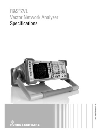
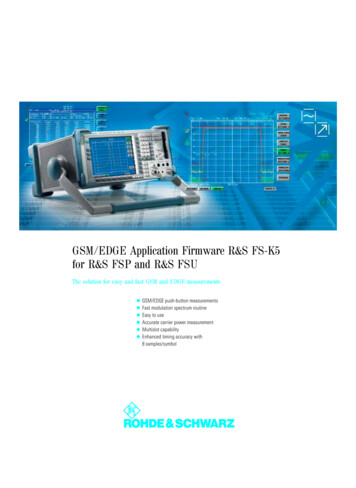
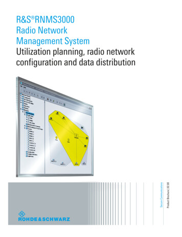
UNRIVALED S IGNAL INTEGRITY 10-bit ADC: 1024 levels, 4 times more than 8-bit ADC 0.6 % noise: at 1 mV/div, 200 MHz, 50 Ω; % of full scale 500 µV/div: full bandwidth, no software magnification10-bit ADC with up to 16-bit resolution500 µV/div: full measurement bandwidthRohde & Schwarz engineered a proprietary 10-bit A/D converter that delivers a fourfold improvement over conventional 8-bit A/D converters.The R&S RTA4000 oscilloscope offers outstanding sensitivity down to 500 µV/div. Traditional oscilloscopes canonly reach this level of input sensitivity by employing software-based magnification of larger settings or by limitingthe bandwidth. The R&S RTA4000 oscilloscope shows thesignal’s real sampling points over the full measurementbandwidth – even at 500 µV/div.The increased resolution results in sharper waveforms withmore signal details that would otherwise be missed. Oneexample is the characterization of switched-mode powersupplies. The voltages across the switching device mustbe determined during the on/off times within the same acquisition. For precise measurements of small voltage components, a high resolution of more than 8 bit is essential.With high resolution decimation, the R&S RTA4000 evenprovides up to 16-bit vertical resolution, a resolution previously unseen in this class of instrument.Class-leading low noiseHigher resolution is only beneficial if the extra bits arenot consumed by the noise of the oscilloscope. TheR&S RTA4000 has class-leading low noise that allows youto take advantage of the extra bits of resolution and seesignals that are hidden in the noise of other oscilloscopes.The Rohde & Schwarz designed 10-bit A/D converter ensures highest signal fidelity athighest resolution10-bit A/D converter: uncovers even small signal detailsTraditional oscilloscope 8-bit vertical resolution RTA4000 10-bit vertical resolutionFinest resolution for a 1 V signal4 mV41 mV
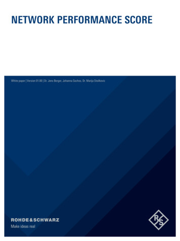
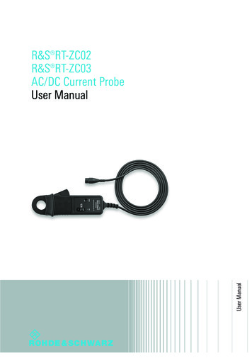
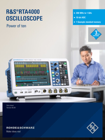
CAPTURE MORE TIMEAT FULL BANDWIDTH 200 Msample: standard acquisition memory 1 Gsample: standard history and segmented mode 0.5 ppm: timebase accuracyDeep memory: standard 100 Msample per channel and200 Msample interleavedThe R&S RTA4000 offers class-leading memory depth:100 Msample per channel, 200 Msample in interleavedmode. This is up to 10 times more than similar oscilloscopes in the same instrument class. Maintaining a fastsample rate is directly tied to acquisition memory. With itsdeep memory, the R&S RTA4000 captures longer periodsof time at high sample rates, giving you extra insurance forunexpected project requirements.Standard segmented memory: 1 GsampleThe standard segmented memory analyzes signal sequences over a long observation period. For example, protocol-based signals with communications gaps, such asI2C or SPI, can be captured over extended periods of timewithout wasting storage on idle time. Thanks to the variable segment size from 10 ksample to 200 Msample, thedeep memory is optimally utilized; more than 87 000 cohesive individual segments are possible.Standard history functionClass-leading timebase accuracyWith a timebase accuracy of 0.5 ppm, the R&S RTA4000is 5 to 20 times better than other instruments in its class.An excellent timebase is important to ensure accuratemeasurements over long time captures.History mode is an always-on capability to view p reviousacquisitions up to the maximum segmented memorydepth of 1 Gsample. For further analysis, the completetoolset can be applied to recorded segments. This includes, for example, mask tests, QuickMeas function andFFT.10 to 50 times more memory depth than traditional oscilloscopes in the same instrument classCapture the longest time periods with class-leading 1000 Msample memory RTA4000Comparableoscilloscopes20Standard memory2001000Standard segmented memoryRohde & Schwarz R&S RTA4000 Oscilloscope 5
LARGE HIGH-RESOLUTION DISPLAY IN A CQuick access to important tools Drag & drop to use analysis tools Toolbar to access functions User-defined shortcuts allow fast adjustment of functionsEasily customizable waveform displaywith R&S SmartGrid technology Configurable display Resizable waveform areas Scales labeled on all axes10 second boot timeCompact form factor Small footprint Less than 3.3 kg Only 28.3 dB(A) audible noise6Vertical zoom Zoom both horizontally and vertically onwaveforms without overdriving the frontend
COMPACT FORM FACTOR10.1" high-resolution capacitive touchscreenwith gesture support Gesture support for scaling and zooming High resolution: 1280 800 pixel 12 horizontal grid lines for more signal detailsDocumentation of results at thepush of a button Documentation as a screenshot or ofinstrument settingsIntegrated logic analyzer (MSO) 16 additional digital channels Synchronous and time-correlated analysisof analog and digital components ofembedded designs User upgradeableColor-coded controls indicate the selected channelStandard history function Always-on capability to view previousacquisitions Over 1 Gsample More than 87 000 segmentsActive probe interface Automatically detects and powers probes Rohde & Schwarz probes with probeinterface More than 30 available probesRohde & Schwarz R&S RTA4000 Oscilloscope 7
FREQUENCY R ESPONSE A NALYSIS(BODE PLOT) Analyze the frequency response of passive filters and amplifier circuits Perform control loop response measurements Perform power supply rejection ratio measurements Simple and fast documentationPerform low-frequency response analysis with an oscilloscopeThe R&S RTA-K36 frequency response analysis (Bode plot)option lets you perform low-frequency response a nalysison your oscilloscope easily and quickly. It characterizesthe frequency response of a variety of electronic devices,including passive filters and amplifier circuits. For switchmode power supplies, it measures the control loop response and power supply rejection ratio.The frequency response analysis option uses the oscilloscope’s built-in waveform generator to create stimulus signals ranging from 10 Hz to 25 MHz. Measuring the ratioof the stimulus signal and the output signal of the DUT ateach test frequency, the oscilloscope plots gain and phaselogarithmically.The R&S RTA-K36 frequency response analysis (Bode plot) option characterizes the frequency response of a variety of electronic devices, including p assive filters and amplifiercircuits8
The amplitude output level of the generator signal can be varied during the measurement to suppress the noise behavior of the DUTFeatures and functionalitiesAmplitude profileThe R&S RTA-K36 frequency response analysis (Bode plot)option allows users to profile the amplitude output level ofthe generator. This helps to suppress the noise behaviorof the DUT when performing a control loop response orpower supply rejection ratio and to improve signal-to-noiseratio (SNR). It is possible to define up to 16 steps.Improve resolution and markers supportThe measurement resolution can be varied by changing the points per decadeYou can choose the points per decade to set up and modify the resolution of your plot. The oscilloscope supportsup to 500 points per decade. Markers can be dragged tothe desired position, directly on the plotted trace. A legenddisplays the corresponding coordinates of the markers. Todetermine the crossover frequency, set one marker to 0 dBand the second marker to –180 phase shift. Now you caneasily determine the phase and gain margin.Measurement tableFurthermore, you can view the results in a table. The tableof measurement results details information about eachmeasured point, consisting of frequency, gain and phaseshift. In case you use cursors, for ease of use, the associated row of the result table is highlighted. For reporting,screenshots, table results or both can be quickly saved toa USB device.Broad probe portfolioA table of measurement results provides detailed information about each measurement point, consisting of frequency, gain and phase shiftAccurate control loop response or power supply rejectionratio characterization highly depends on choosing the rightprobes, since peak-to-peak amplitudes of both Vin and Voutcan be very low at some test frequencies. These valueswould be buried in the oscilloscope’s noise floor and/or inthe switching noise of the DUT itself. We recommend thelow-noise R&S RT-ZP1X 38 MHz bandwidth 1:1 passiveprobes. These reduce measurement noise and provide thebest SNR.R&S RT-ZP1X 38 MHz bandwidth1:1 passive probeRohde & Schwarz R&S RTA4000 Oscilloscope 9
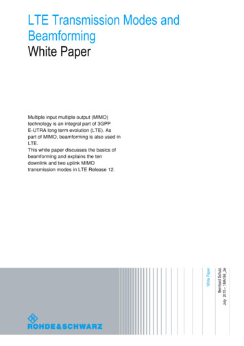
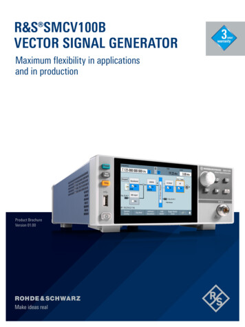
SPECTRUM ANALYSIS: IDENTIFY INTERACTIONS BETWEEN TIMEAND FREQUENCY Spectrogram: evolution over time Peak markers: automatic positioningFast and precise analysisSpectrogram: display of frequency over timeDifficult-to-find faults often result from the interactionbetween time and frequency signals. The R&S RTA-K37spectrum analysis and spectrogram option quickly findssuch errors. Like on a spectrum analyzer, parameterssuch as center frequency and resolution bandwidth canbe adapted to the specific measurement task. The oscilloscope automatically selects the relevant time domain settings. Optimum performance ensures the fastest multi-domain analysis in this oscilloscope class.A spectrogram displays the spectrum of frequencies asthey vary over time. For easy interpretation, the magnitude can be color-coded. Thanks to the high FFT rate, evenfast frequency changes can be displayed. When used incombination with the history and segmented memory,the spectrogram marker shows the time of the acquisitionand makes it possible to load the corresponding time andfrequency waveforms onto the screen. All R&S RTA4000tools can be used to analyze the loaded waveforms.Parallel operation: correlation between frequency and timeMarkers: find peaks automaticallyAdvanced electronics is based on the seamless interactionbetween protocol-based interfaces, digital, analog and frequency components. Simultaneous analysis of all components is a must. Time, frequency and protocol informationis correlated, and time references can be quickly recognized. Measurement windows help you select specific areas of the recording, which can simplify, for example, theacquisition of frequency switching operations.Markers can be automatically positioned on the frequencypeaks for fast analysis. An adaptable threshold defines thepeaks. Parameters such as excursion and maximum peakwidth can be adjusted for in-depth analysis. Results can becompiled in a table (absolute or relative to a specific reference marker). Selectable delta measurements make it easyto adjust the distances between signal peaks.Test signal from three different perspectives: time domain (top), spectrogram (center) and frequency domain(bottom)10
PROTOCOL ANALYSIS: EFFICIENTLYDEBUG SERIAL BUSESProtocol aware triggering and decoding for serial busesCounting 1s and 0s to decode a serial bus is tedious anderror-prone. The R&S RTA4000 automates this process bydecoding the waveforms into a specific protocol. In addition, protocol aware triggering directly triggers on specificparts of a packet or frame.Segmented memory for long time capturesStandard segmented memory is ideal for serial protocols. It allows you to capture only relevant packets/framesand ignore the long idle time in between packets. With1 Gsample of segmented memory available, you can capture more than 87 000 timestamped packets/frames.Table view of packets/framesA table view allows you to see a high-level representationof all captured packets. You can also export the table.Supported buses I2CUART/RS-232/RS-422/RS-485SPI (2/3/4-wire)MIL-STD-1553ARINC 429CANLIN I2S/LJ/RJ/TDM Embedded AerospaceAutomotive, industrialAudio Decoded hexadecimal I²C messageshown in honeycomb format and intableRohde & Schwarz R&S RTA4000 Oscilloscope 11
THE RIGHT PROBE FORTHE BEST MEASUREMENT More than 30: dedicated probes Micro button: for convenient instrument control 0.01 % accuracy: with R&S ProbeMeterExtensive probe range for all measurement tasksA complete portfolio of high-quality passive and activeprobes covers all measurement tasks. With an input impedance of 1 MΩ, the active probes put only a minimumload on a signal source’s operating point. The very largedynamic range, even at high frequencies, prevents signaldistortion – for example: 60 V (Vpp) at 1 GHz for the activesingle-ended probes.R&S ProbeMeter: integrated voltmeter for preciseDC measurementsOne connection lets you see the oscilloscope waveform and gives you access to a highly accurate voltmeterthat shows the DC value regardless of other instrumentsettings. For more information, see the product brochure:Probes and accessories for Rohde & Schwarz oscilloscopes(PD 3606.8866.12).Complete portfolio for power measurementsThe portfolio of dedicated probes for power measurements includes active and passive probes for the differentvoltage and current ranges – from μA to kA and from μVto kV. Dedicated power rail probes detect even small andsporadic distortions on DC power rails.Micro button for convenient instrument controlThe situation is all too familiar. You've carefully positionedthe probe on the device under test and want to start themeasurements – but you don't have a free hand. The microbutton on Rohde & Schwarz active probes solves this problem. It is conveniently situated on the probe tip, and youcan assign it different functions, such as run/stop, autosetand adjust offset.Practical design: micro button for convenient instrument control; diverse probe tipsand ground cables are included as standard accessoriesProbe typeIdeal for measuringRecommended probesSingle-ended voltages, max. bandwidth 500 MHzR&S RT-ZP10 comes as standard with theR&S RTA4000Active broadband probeSingled-ended voltages, up to 8 GHz bandwidthR&S RT-ZS10E, R&S RT-ZS10, R&S RT-ZS20Power integrity probeDisturbances on power rails with high offsets, greater than2 GHz bandwidthR&S RT-ZPR20High voltage probeHigh single-ended and differential voltages, up to 6 kVCurrent probeCurrents from µAs to kAsEMC near-field probeEMI debugging up to 3 GHzStandard passive probe12R&S RT-ZHD007, R&S RT-ZHD15, R&S RT-ZHD16,R&S RT-ZHD60R&S RT-ZC05B, R&S RT-ZC10B, R&S RT-ZC15B,R&S RT-ZC20B, R&S RT-ZC30R&S HZ-15
COMMON APPLICATIONSPower integrity Measure large DC offsets with the ability to zoom in onsmall ripplesAccurately measure ripple and periodic and random disturbances(PARD)Spectrum analysis view makes finding coupled sources easierPower analysis See power signal details with up to 16-bit resolutionCapture long periods of time, e.g. a turn-on sequence, with highsample rateComplete probe portfolio for measuring from µA to kA andµV to kVEMI debugging Near-field probes allow you to sniff out interfering signalsTime and frequency domain correlation for powerful debugging ofemittersFFT provides a vivid and fast view in the frequency domainRohde & Schwarz R&S RTA4000 Oscilloscope 13
CAPABILITIES TO MEET YOUR NEEDS TODAcquisition modes High-resolution: up to 16-bit vertical resolutionAveraging: up to 100 000 waveformsPeak detectEnvelopeAveraging plus high resolutionEnvelope plus peak detectEnvelope plus high resolutionMath and measurements Up to five basic or advanced math waveformsAdvanced math includes equation editor with 30 optionsUp to eight measurements at onceOver 40 automated measurement options available for eachmeasurementGated measurements and statisticsAnnotation, R&S SmartGrid and documentation Simplified documentation at the push of a buttonOn-screen annotation using the touch display forspecific notesR&S SmartGrid to easily resize/layout/configure the display asneededGraticule annotation makes it easy to quickly see the V/divand timebase settingDigital voltmeter 14Integrated 3-digit voltmeter (DVM)Integrated 6-digit frequency counterAlways on, even when the oscilloscope is stoppedMeasurement functions include DC, AC DC (RMS) andAC (RMS)
DAY WITH INSURANCE FOR THE FUTUREMixed signal Integrated digital channels (16 channels) allow correlatedmeasurements between analog and digital signalsUp to 5 Gsample/s sample rate for high timing resolutionUp to 200 Msample of memory allows long time capturesIdeal for low-speed serial bus analysisWaveform and pattern generator Integrated arbitrary waveform generator to produce signals fordevice stimulusHigh sample rate (250 Msample/s) and resolution (14 bit) allowsaccurate signal reproductionModulation and swept mode capabilities50 Ω (2.5 V (Vpp)) and 1 MΩ (10 V (Vpp)) output4-bit pattern generator with predefined patterns and the ability toimport user-defined patternsXY mode Plot the voltage levels of two channels against each otherMeasure phase shiftMask test mode Fast limit testing to see if a waveform violates a configured set ofconditionsImport user-defined masks or create a mask of a known goodwaveform on the oscilloscopeSave screenshots, waveforms; output a beep or pulse onviolationsRohde & Schwarz R&S RTA4000 Oscilloscope 15
AND THERE IS SO MUCH MORE . Efficient reporting capabilities Localized GUI and online help Fully upgradeable via software licenses Web server functionality for instrument access Extensive range of probes and accessoriesGrows with your needsProtection of dataThe R&S RTA4000 oscilloscopes flexibly adapt to neededproject updates. You simply install the necessary softwarelicenses, e.g. triggering and decoding of serial protocols.The waveform and pattern generator and MSO capabilities 1) are built-in and just need to be activated. The bandwidth can be upgraded up to 1 GHz via keycode. All thismakes retrofitting really easy.The secure erase function protects sensitive data. Thisfunction removes all user data and settings, including device setups and reference waveforms.Multilingual support: choose among thirteen languagesThe R&S RTA4000 oscilloscope’s user interface and onlinehelp support thirteen languages (English, German, French,Spanish, Italian, Portuguese, Czech, Polish, Russian, simplified and traditional Chinese, Korean and Japanese). Youcan change the language in just a few seconds while theinstrument is running.1)ConnectivityThe R&S RTA4000 can be directly connected to a PC viathe built-in USB host and USB device ports. The USB hosttransfers screenshots and instrument settings to a USBstick. Media transfer protocol (MTP) implementation ensures seamless integration. The USB device port and theLAN interface enable remote control. The built-in webserver functionality allows you to control the oscilloscopeand display your screen content to an audience. Data andprogramming interfaces are included, e.g. for seamlessMATLAB integration.The R&S RTA-B1 MSO option additionally contains two logic probes with16 d igital channels.With the USB MTP implementation, you can easily access live channel data and screenshots and i ntegrate the oscilloscope into your computing environment16
Base unitVertical systemInput channelsInput impedanceR&S RTA4004Analog bandwidth (–3 dB)at 50 Ω input impedanceR&S RTA4004R&S RTA4004 with -B243 optionR&S RTA4004 with -B245 optionR&S RTA4004 with -B2410 optionat 1 MΩ input impedanceR&S RTA4004 withR&S RTA4004 with -B243 optionR&S RTA4004 with -B245 optionR&S RTA4004 with -B2410 optionat AC couplingat 50 Ω input impedanceR&S RTA4004R&S RTA4004 with -B243 optionR&S RTA4004 with -B245 optionR&S RTA4004 with -B2410 optionLower frequency limit (–3 dB)Analog bandwidth limitsRise time (calculated)at 1 MΩ input impedanceR&S RTA4004R&S RTA4004 with -B243 optionR&S RTA4004 with -B245 option andR&S RTA4004 with -B2410 optionR&S RTA4004R&S RTA4004 with -B243 optionR&S RTA4004 with -B245 optionR&S RTA4004 with -B2410 optionVertical resolutionInvert signalDC gain accuracyInput couplingInput sensitivityMaximum input voltagePosition rangeOffset range at 50 ΩOffset range at 1 MΩoffset and position 0maximum operating temperature change ofinput sensitivity 5 mV/divinput sensitivity 5 mV/div to 1 mV/divinput sensitivity 1 mV/divat 50 Ωat 1 MΩat 50 Ωat 1 MΩinput sensitivity 112 mV/div to 1 V/div 33.8 mV/div to 111 mV/div0.5 mV/div to 33.6 mV/divinput sensitivity 515 mV/div to 10 V/div 50.5 mV/div to 510 mV/div0.5 mV/div to 50 mV/divOffset accuracyDC measurement accuracyChannel-to-channel isolation(each channel at same input sensitivity)17after adequate suppression ofmeasurement noise by using either highresolution sampling mode or waveformaveraging, or a combination of bothinput frequency analog bandwidthRohde & Schwarz R&S RTA4000 Oscilloscope4 channels50 Ω 1.5 % (meas.)1 MΩ 1 % 14 pF 1 pF (meas.) 200 MHz 350 MHz 500 MHz 1 GHz 200 MHz (meas.) 350 MHz (meas.) 500 MHz (meas.) 500 MHz (meas.) 5 Hz (meas.)20 MHz, 100 MHz20 MHz, 100 MHz, 200 MHz20 MHz, 100 MHz, 200 MHz, 350 MHz20 MHz, 100 MHz, 200 MHz, 350 MHz,500 MHz20 MHz, 100 MHz20 MHz, 100 MHz, 200 MHz20 MHz, 100 MHz, 200 MHz, 350 MHz 1.75 ns 1 ns 700 ps 350 ps10 bit, up to 16 bit with high resolutiondecimationyes 5 C after self-alignment 1 % 1.5 % 2.5 %DC, AC, GND0.5 mV/div to 1 V/div0.5 mV/div to 10 V/div5 V (RMS), max. 30 V (Vp)300 V (RMS), 400 V (Vp), derates at20 dB/decade to 5 V (RMS) above250 kHz 5 div (30 V – 5 div input sensitivity) (10 V – 5 div input sensitivity) (2 V – 5 div input sensitivity) (250 V – 5 div input sensitivity) (25 V – 5 div input sensitivity) (2 V – 5 div input sensitivity) (0.5 % offset 0.1 div input sensitivity 0.5 mV) (DC gain accuracy reading – netoffset offset accuracy) 50 dB
RMS noise floor at 1 MΩ (meas.)RMS noise floor at 50 Ω (meas.)Input sensitivity10 V/div5 V/div2 V/div1 V/div500 mV/div200 mV/div100 mV/div50 mV/div20 mV/div10 mV/div5 mV/div2 mV/div1 mV/div0.5 mV/divInput sensitivity1 V/div500 mV/div200 mV/div100 mV/div50 mV/div20 mV/div10 mV/div5 mV/div2 mV/div1 mV/div0.5 mV/divR&S RTA4004271 mV161 mV64 mV38 mV16 mV6 mV3.6 mV1.6 mV0.7 mV0.4 mV0.21 mV0.14 mV0.13 mV0.12 mVR&S RTA400427 mV15 mV8 mV3.2 mV1.7 mV0.7 mV0.3 mV0.18 mV0.08 mV0.08 mV0.06 mVRTA4004 with-B243 option300 mV172 mV70 mV43 mV17 mV7 mV4.1 mV1.6 mV0.8 mV0.4 mV0.25 mV0.18 mV0.14 mV0.13 mVRTA4004 with-B245 option370 mV230 mV100 mV60 mV23 mV10 mV5.80 mV2.10 mV1.10 mV0.60 mV0.33 mV0.24 mV0.18 mV0.17 mVRTA4004 with-B2410 option370 mV230 mV100 mV60 mV23 mV10 mV5.80 mV2.10 mV1.10 mV0.60 mV0.33 mV0.24 mV0.18 mV0.17 mVRTA4004 with-B243 option27 mV16 mV9 mV3.6 mV1.9 mV0.8 mV0.3 mV0.22 mV0.11 mV0.09 mV0.08 mVRTA4004 with-B245 option30 mV18 mV10 mV4.1 mV2.2 mV0.8 mV0.4 mV0.24 mV0.12 mV0.1 mV0.1 mVRTA4004 with-B2410 option38.0 mV24.0 mV13.0 mV5.50 mV2.90 mV1.10 mV0.50 mV0.33 mV0.16 mV0.14 mV0.13 mVHorizontal systemTimebase rangeChannel deskewTrigger offset rangeModesChannel-to-channel skewTimebase accuracyDelta time accuracyselectable between0.5 ns/div and 500 s/div 500 nsminimum𝑚𝑒𝑚𝑜𝑟𝑦 𝑑𝑒𝑝𝑡ℎ𝑎𝑐𝑡𝑢𝑎𝑙 𝑠𝑎𝑚𝑝𝑙𝑖𝑛𝑔 𝑟𝑎𝑡𝑒maximum233𝑎𝑐𝑡𝑢𝑎𝑙 𝑠𝑎𝑚𝑝𝑙𝑖𝑛𝑔 𝑟𝑎𝑡𝑒after delivery/calibration, at 23 Cduring calibration intervalcorresponds to time error between toedges on same acquisition and channel;waveform sample rate Fs can be obtainedvia SCPI command "ACQ:SRAT?";signal amplitude greater than 5 divisions,measurement threshold set to 50 %,vertical gain 10 mV/div or greater;rise time lower than 4/Fs;waveform acquired in sample modenormal, roll 200 ps (meas.) 0.5 ppm 1 ppm (1.34/Fs timebase accuracy reading ) (peak) (meas.)Rohde & Schwarz R&S RTA4000 Oscilloscope18
Acquisition systemMaximum realtime sampling rateMemory depth per channelAcquisition modesnormal modeinterleaved mode,if following channels are not usedsimultaneously: channel 1 and channel 2 channel 3 and channel 4 logic channelsnormal modeinterleaved mode,if following channels are not usedsimultaneously: channel 1 and channel 2 channel 3 and channel 4 logic channelssamplepeak detecthigh resolutionenvelopeaverageenvelope peak detectenvelope high resolutionaverage high resolutionNumber of averaged waveformsWaveform acquisition ratedot display, single channel, auto recordlength2.5 Gsample/s5 Gsample/s100 Msample per channel200 Msample per channelfirst sample in decimation intervallargest and smallest sample in decimationinterval (400 ps detection)average value of all samples in decimationintervalenvelope of acquired waveformsaverage over a series of acquiredwaveformsenvelope of acquired waveforms withactive peak detectenvelope of acquired waveforms withactive high resolutionaverage over a series of acquired highresolution waveforms2 to 100 000up to 64 000 waveforms/sTrigger systemTrigger levelTrigger modesHold-off rangeTrigger typesrangetimeactions on triggerEdge trigger Atrigger eventsR&S RTA4004trigger couplingtrigger filterselectable trigger hysteresis19Rohde & Schwarz R&S RTA4000 Oscilloscope 5 div from center of screenauto, normal, single, n singleinactive or 51.2 ns to 13.7 sedge, width, video, pattern, runt, rise time,fall time, serial bus, line, timeoutpulse, sound, screenshot, save waveform,save reference waveformrising edge, falling edge, both edgeschannel 1, channel 2, channel 3,channel 4, logic channels from D15 to D0(with R&S RTA-B1 option), externaltrigger inputDC,AC (attenuates 10 Hz (meas.)),LF reject (attenuates 10 kHz (meas.))HF reject (attenuates 100 kHz (meas.)),noise reject (attenuates 100 MHz(meas.))automatic, small, medium, large
Trigger A sensitivity hysteresis modeautomaticwith DC, AC, LF reject, noise reject1 GHz, 500 MHz, 350 MHz 2.2 𝑚𝑉𝑝𝑝 1 𝑑𝑖𝑣 (𝑛𝑜𝑚. )𝑖𝑛𝑝𝑢𝑡 𝑠
Designed with class-leading signal integrity and responsive ultra-deep memory, the R&S RTA4000 brings the power of 10 to a new level. A Rohde & Schwarz designed 10-bit ADC combined with class-leading low noise, memory depth and timebase accuracy gives you sharp waveforms, more accurate measurements and confidence when facing