Transcription
NETWORK PERFORMANCE SCOREWhite paper Version 01.00 Dr. Jens Berger, Johanna Sochos, Dr. Marija Stoilkovic
CONTENTS1Introduction .42Basic structure .53Voice telephony .63.13.1.13.1.23.1.33.2Voice telephony contributors . 6Accessibility and retainability – success ratio . 6Call setup time . 6Perceptual objective listening quality analysis (POLQA) in line with ITU-T P.863 . 7Contributors transformation to a percentage scale . 84Data services 2Data transfer services . 9Availability/accessibility – HTTP UL/DL success ratio . 9Data transfer performance – HTTP DL/UL throughput . 10Data transfer services – contribution and weighting . 11Video streaming services . 11Typical video streaming service structure . 12Video streaming services performance contributors . 12Video streaming services – contribution and weighting . 13HTTP browsing and social media . 13HTTP browsing . 13Browsing/social media – contribution and weighting . 155Regions and final aggregation categorization .166Point score application .177Summary .20Appendix A .21A-1 Testing HTTP browsing in benchmarking campaigns .21A-1.1A-1.2A-1.3A-1.42Introduction . 21Selection criteria for websites . 21Best practice for selecting websites . 23Websites in benchmarking campaigns – statistical analysis . 23A-2Measurement scenarios 3.2A-2.3.3A-2.3.4A-2.4A-2.5A-2.6Job structures . 26Call session . 26Data session . 26Voice test settings . 27Double ended call settings . 27Data test settings . 27Ping testing . 27Data transfer testing . 28Video streaming service testing . 30HTTP browsing and social media service testing . 30Rohde & Schwarz measurement systems . 31NPS campaign setup in SmartBenchmarker . 33Postprocessing . 35
Appendix B .37B-1Network performance score (NPS V1.0) .37B-1.1 KPIs, weightings and thresholds . 37B-1.2 Maximum scoring points per category . 38B-1.3 Improvement in points . 39B-1.4 Abbreviations . 41Customer support .42Technical support – where and when you need it . 42Up-to-date information and upgrades . 42Regional contact . 42This white paper describes the structure and application of anintegrated and transparent methodology to characterize mobilenetwork performance.Rohde & Schwarz White paper Network Performance Score 3
1INTRODUCTIONThe perceived technical performance of a network depends on how satisfied users arewith the quality and availability of telecommunications services. Smartphones are notonly used for telephony and text messaging services; today, they are predominately usedfor over-the-top (OTT) data services.There is a demand for an efficient method of calculating an overall score that reflects theperceived technical performance of a network or one of its subsets, such as a region, aperiod of time or a technology. The method described here considers and weights the keyperformance indicators (KPI) for a wide range of services that are essential for and representative of the service quality and combines them into an overall performance score.This score can be calculated for individual regions such as cities, highways and popularareas. The scores of the individual regions are then aggregated in an overall network performance score.There are two approaches to aggregation: Applying a scaling of 0 % to 100 % to each level. This allows direct comparison ofindividual regions or service types and is used for benchmarking purposes. Assigning points to each individual subscore instead of applying a scaling. Themaximum number of points for a KPI or a subscore is defined by its weighting in theoverall score based on the weighting of the service category, e.g. telephony or data,and the weighting of the regional category, e.g. city or road. All points are accumulatedto determine the overall score in points. This point scale (from 0 to 1000) can beconsidered a network optimization tool since it makes it easy to identify the best placeto improve the overall performance.Between these two scales, there is a transformation of the applied weightings for the individual services. Section 2 Basic structure to section 5 Regions and final aggregationcategorization explain the KPIs used and the structure of the score based on the percentage score. The point score is explained separately in section 6 Point score application.The scoring mechanism allows very efficient comparison of operators in a market, of different measurement campaigns in regions and countries, or before and after deployment of new technology or software. The transparent structure of the score allows efficient drilldown to the region, service or even the KPIs responsible for a nonoptimal overallscore.The scoring methodology is in line with the current state of the ETSI TR 103 559 V1.1.1and is available in Rohde & Schwarz mobile network testing (MNT) products as networkperformance score version 1.1.This score only takes into account the technical performance of the services; other dimensions of user satisfaction such as billing, tariffs and support quality are not considered.4
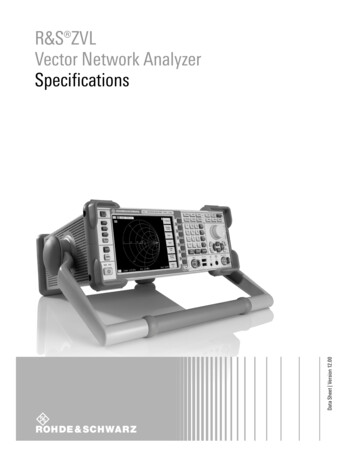
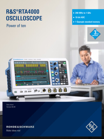
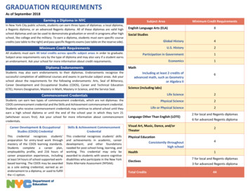
BASIC STRUCTUREThe structure of the network performance score is highly transparent and consists of different layers of weighting and accumulation.On the technical side, the score is based on telephony and data services subscores, eachof which is scaled separately from 0 % to 100 %. Each of these two subscores consistsof a set of comprehensive KPIs or contributors. Today, the subscores have weightings of40 % telephony and 60 % data services and form a complete network score.Fig. 1: Network performance score basic structure0 % to 100 %Telephony0 % to 100 %40 %0 % to 100 %Data services60 %It is possible to apply an additional intermediate weighting layer that gives d ifferentweightings for individual regions and categories such as cities, connecting roads,hotspots and rural areas. The weighted and cumulative scores for the subregions againrange from 0 % to 100 %.Fig. 2: Network performance score subregionsData servicesTelephonyCities0 % to 100 %xData services0 % to 100 %Data servicesTelephonyConnecting roads0 % to 100 %0 % to 100 %y.SpotsTelephony2zThe number, categorization and weighting of these regions is flexible and can be definedto meet regional or national needs. This regional categorization is described in section 5Regions and final aggregation categorization.Rohde & Schwarz White paper Network Performance Score 5
3VOICE TELEPHONYThe telephony subscore is based on the end-user experience of telephony services.Service availability, accessibility, retainability and performance are evaluated to determinethe score.3.1 Voice telephony contributorsThe contributors (KPIs) for telephony performance are: Call setup success ratio (CSSR) Call drop ratio (CDR) Call setup time (CST) average CST 15 s ratio CST 10th percentile Voice mean opinion score (MOS) average Voice MOS 1.6 ratio Voice MOS 90th percentileThe contributors are described in more detail in the following.3.1.1 Accessibility and retainability – success ratioCall setup success ratio (CSSR) is the percentage of all attempts to make a call that result in a connection to the dialed number. Typical ratios are between 90 % and 100 %.CSSR is a straightforward calculation:CSSR Number of successfully established callsNumber of attemptsNote: S uccessfully established calls include completed calls and established but droppedcalls. Attempts include completed, dropped and failed calls.Call drop ratio (CDR) is the percentage of telephone calls that were cut off due to technical reasons before the speaking parties finished their conversation and before one ofthem intentionally hung up. This KPI is measured as a percentage of all successfully established calls. Typical scores are 10 %.The formula only considers completed and dropped calls as successfully established:CDR Number of dropped callsNumber of completed Number of dropped calls3.1.2 Call setup timeIn Rohde & Schwarz SwissQual measurement systems, the call setup time (CST) is takenfrom the application layer. The CST is the time interval from the point when the user startsdialing until the call is reported as connected to the user. It takes into account both thetelephone software’s configuration and processing times, and results in a setup time asperceived by the user.Note: T here is a difference between the CST described above and the shorter call setuptimes measured at the signaling level.Call setup time (CST) average is the overall average performance of the network or ofthe applied selection of measurements. This value is calculated as the average of all measured CSTs for all completed and dropped calls.6
CST 15 s ratio is a KPI used to identify poor performers. Usually, the contribution ofthis KPI is important due to fact that users have a very negative perception when something goes wrong while they consider exceptional service as the norm.CST 10th percentile is the threshold below which the shortest 10 % of CST values fall.This score rewards best performers and gives an indication of the shortest CST reachablein a technology or region. The 10 % percentile value also indicates a good practice expectation of what is possible with respect to the CST for a region, technology or weighting.3.1.3 Perceptual objective listening quality analysis (POLQA) in line with ITU-T P.863To assess the speech quality provided by mobile operators, three KPIs are defined basedon the ITU-T P.863 (POLQA) MOS. ITU-T P.863 is used in its super-wideband/fullbandmode to access HD voice/wideband channels correctly. The applied ITU-T P.863 algorithmconsiders the full audio spectrum applied to EVS-SWB and FB codecs as deployed inVoLTE.The POLQA scores are evaluated per speech sample, each call delivering multiple individual scores into the analysis in both directions of the conversation (half-duplex).The absolute POLQA score depends on the test speech signal used. It is recommendedto use reference signals specified in ITU P.501 Annex D and apply the same signal for allmeasurements in a campaign for comparison reasons. A good example is the English testsample “EN fm P501”, which is part of the Rohde & Schwarz system installation.Voice MOS average measures the overall, average speech quality performance of anetwork or a selection of measurements. This KPI is the plain average of all consideredPOLQA scores without any further preselection, exclusion or weighting. Typical MOSscores are around 3.0 for narrowband channels and 3.5 to 3.7 for wideband (HD voice)channels.Note: S ilence in the audio channel is not part of the mean opinion score (MOS); it is indirectly considered, either by failed calls due to silence or by dropped calls where silence typically occurs shortly before a call drops.Voice MOS 1.6 ratio is the ratio of very bad speech samples. Considering the strongnegative perception of low quality, this score explicitly penalizes high ratios of badsamples.Voice MOS 90th percentile is the threshold above which the best 10 % of voice MOSvalues fall. It rewards good performers, keeping in mind that users perceive very goodperformance very positively. It also gives an indication of the MOS scores that are attainable with a given setup or technology (based on the applied selection of measurementdata).Rohde & Schwarz White paper Network Performance Score 7
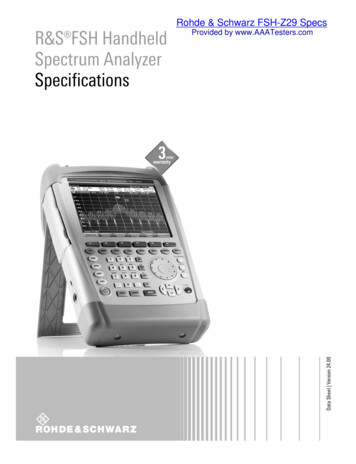
3.2 Contributors transformation to a percentage scaleThe described contributors are scaled according to their original units, i.e. seconds for theCST, MOS for speech quality and percentage for all ratios. To ensure the transparency andcomparability of the actual contribution of each contributor/KPI to the voice telephonysubscore, each contributor is also scaled on a percentage scale.The transformation applies a linear weighting of 0 % to 100 % between a bad and goodthreshold. Scores outside of these boundaries stay saturated.Fig. 3: Linear weighting100 %0%Low threshold “bad”High threshold “good”Generally, 0 % is assigned to the bad threshold and 100 % is assigned to the good threshold. The assignment depends on the contributor: for the call success ratio or the averagespeech quality, a high score is used as the good threshold; for the call drop ratio or theaverage call setup time, a high score is considered bad and is used as the bad threshold.The terms bad and good refer to the contribution in terms of quality.For each contributor, bad and good thresholds are defined in the same way as theweighting in the telephony subscore. The table shows these thresholds as applied in theinitial Rohde & Schwarz SwissQual implementation.For each contributor, the following formula is applied:KPI value – Bad thresholdContributor Norm 100 % Weighting Contr Good threshold – Bad thresholdTable 1: NPS voice contributors (Rohde & Schwarz implementation)Bad thresholdGood thresholdWeighting intelephonyCall setup success ratio (CSSR)85.00 %100.00 %0.3125Call drop ratio (CDR)10.00 %0.00 %0.3750Call setup time (CST) average12.004.500.0625CST 15 s ratio3.00 %0.00 %0.0875CST 10th percentile8.004.000.0375Voice MOS average2.004.300.0438Voice MOS 1.6 ratio10.00 %0.00 %0.0562Voice MOS 90th percentile4.004.750.0250Sum81.0
4DATA SERVICESThe data services subscore consists of three areas of contributors addressing differenttypes of services and characterizing different types of requests in a network: (Plain) data transfer (HTTP) (25 %) Video streaming (22 %) HTTP browsing (38 %) and social media (15 %)Similar to voice telephony, each area consists of a set of individual contributors quantifying the typical midrange, rewarding outstanding performers and giving an e xtra bonus foroperators with little or no bad performance.4.1 Data transfer servicesThe plain data transfer performance is calculated by HTTP download and upload.Availability/accessibility and transfer performance are separated.For availability/accessibility, a file of a fixed size is completely downloaded.For the transfer performance, multiple connections are opened and the transfer rate ismeasured for a given time. This test is also known as the capacity test.The individual contributors to this area are: HTTP UL/DL success ratio HTTP DL throughput average HTTP DL throughput 10th percentile HTTP DL throughput 90th percentile HTTP UL throughput average HTTP UL throughput 10th percentile HTTP UL throughput 90th percentile4.1.1 Availability/accessibility – HTTP UL/DL success ratioThe HTTP UL/DL success ratio measures the data service availability/accessibility. It is theratio of successfully completed tests (completed downloads and uploads) to all startedtests. It rates both nonavailability and incomplete uploads and downloads in one score.HTTP UL / DL success ratio Number of successfully completed testsNumber of attemptsSuccessfully completed tests are tests with ErrorCode 0 (state success). Attempts include successfully completed tests and tests with ErrorCode 0 (state test timeout,HTTP request timeout, file transfer failed, etc.).The applied settings for the HTTP UL/DL tests are: Uplink–– File size: 2 Mbyte–– Timeout for completion: 40 s (requires min. 0.4 Mbit/s) Downlink:–– File size: 5 Mbyte–– Timeout for completion: 40 s (requires min. 1.0 Mbit/s)Rohde & Schwarz White paper Network Performance Score 9
4.1.2 Data transfer performance – HTTP DL/UL throughputData throughput is what users experience most of the time while using a data service. Itdepends on many protocol issues such as transmission schemes (slower schemes areused at longer distances from the access point due to better redundancy), packet retransmission and packet size. The typical throughput is often lower due to traffic sharing insidethe same network or cell, interference or even limited fixed line capacity from the basestation onwards.The total duration of an HTTP transfer test is set to 10 s with a connection lost t imeout of3 s and transfer duration of 7 s (see Table 15: HTTP DL test – multi-connection and Table16: HTTP UL test – multi-connection). These parameters are the same for both uploadand download tests. The active transfer duration starts only after all configured TCP sockets have been connected.As an indicator of the average data throughput, the mean data rate (MDR) is calculated.For an HTTP transfer test, the MDR is calculated as the sum of all transferred bytes duringthe test’s active transfer period divided by the transfer time. It is calculated separately forupload and download data.Mean data rate per test all mean data rates per testNumber of testsIn the calculation, all tests with ErrorCode 0 are considered. Tests where the TCP connection could not be established for any or all sockets, tests for which the server is not responding (ErrorCode 0) or tests classified as system release are excluded.HTTP DL/UL throughput average is the main score and quantifies the average transferrate in Mbit/s across a network or an applied selection of measurement data.HTTP DL / UL throughput average all mean data rates per testNumber of testsHTTP DL/UL throughput 10th percentile is a KPI that measures the poor performance of anetwork, i.e. the data rate below which the worst 10 % of transfers fall. It is used to consider the negative perception if there is a very slow transfer that is not well considered inthe average throughput.Example:There are 100 DL tests, 85 with 120 Mbit/s and 15 with just 0.5 Mbit/s. The average MDRis considered good at 102 Mbit/s even if 15 % of the tests have a much lower value. The10 % percentile MDR indicates this with a score of 0.5 Mbit/s. Consequently, such a network is rated lower than one having consistently 102 Mbit/s in all tests.HTTP DL/UL throughput 90th percentile is a KPI that evaluates the good performance ofthe network, i.e. the best 10 % of transfers are above this value. The goal of this KPI is tofind the maximum performance of the network or the selected measurements. The 90 %percentile value is preferred over the absolute maximum (which is just a single test) andis considered a more reliable KPI for showing the network’s full capacity.10
4.1.3 Data transfer services – contribution and weightingThe individual contributors are rescaled on a 0 % to 100 % scale as described in section3.2 Contributors transformation to a percentage scale.For each contributor, the following formula is applied:KPI value – Bad thresholdContributor Norm 100 % Weighting Contr Good threshold – Bad thresholdThe HTTP data transfer performance contributes 25 % to the data services subscore.Table 2: NPS HTTP data transfer contributors (Rohde & Schwarz implementation)Bad thresholdGood thresholdWeighting indata servicesHTTP UL/DL success ratio80 %100 %0.0550HTTP DL throughput average1.0 Mbit/s100.0 Mbit/s0.0350HTTP DL throughput 10th percentile1.0 Mbit/s40.0 Mbit/s0.0450HTTP DL throughput 90th percentile10.0 Mbit/s240.0 Mbit/s0.0175HTTP UL throughput average0.5 Mbit/s50.0 Mbit/s0.0350HTTP UL throughput 10th percentile0.5 Mbit/s30.0 Mbit/s0.0450HTTP UL throughput 90th percentile5.0 Mbit/s100.0 Mbit/s0.0175Sum0.254.2 Video streaming servicesVideo services consume the majority of data transferred in mobile networks and therefore have to be considered. YouTube is the most common service used for v ideo streaming. Besides the pure access times and perceived quality, these tests are very demanding for the network, particularly for ensuring continuous data delivery without outages.Consequently, it is a valuable extension to the plain HTTP data transfer tests where a continuous transfer is not required and cannot be measured.In YouTube – and in all video services – there is a basic difference between live video andvideo on demand (VoD). In the VoD case, the video is completely stored on the serverand is usually completely – or mostly – downloaded to the device; there are many techniques, progressive download being the most common one. Live video is not available asa file. It is sent almost in real time to the device, and in practice, in short portions of a fewseconds each. If VoD is used as the test case, the video is largely buffered on the phoneand outages in the connection can easily be bridged. Live video is much more sensitivesince an interruption in the data flow will lead to freezing a fter a short time. The VoD isthe less sensitive test case and leads to average or higher video quality since there is lessfreezing. Live video is more sensitive and reflects the continuity of the data flow providedby the network.Consideration of live video streams is best practice for network benchmarking today.Rohde & Schwarz White paper Network Performance Score 11
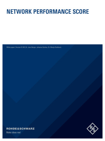
4.2.1 Typical video streaming service structureEach YouTube streaming test can be divided into two phases: the video access phase andthe video playout phase. The video access phase starts with the video request and continues until the first picture is displayed. This time is measured by the KPI video setup timeor time to first picture (TTFP). Video setup time is the time interval from the point whena request to play a video is made to the moment when the video starts to play. It measures the overall performance of the network in terms of accessibility to video streamingservices.Fig. 4: Typical video streaming service structureVideo requestedVideo finishedDisplaying stopped by userStart displayingDNSConnect to serverFirst video packet arrivesPrebufferingAccess phaseVideo playout phaseAfter the playout starts, the perceived video quality is considered as the main contributor.The perceived video quality is determined by compression artifacts, rescaling effects, lower frame rates and freezing (stalling) during the display. The perceived quality is measuredby ITU J.343.1 and combines all possible degradations into one video MOS on a commonscale from 1 to 5. ITU J.343.1 is especially recommended by ETSI TS 102250-2 for evaluating mobile streaming services. The testing methodology for YouTube and other videostreaming services is described in ETSI TR 101578.4.2.2 Video streaming services performance contributorsThe contributors (KPIs) for video stream performance are: Video success ratio Video setup average Video setup 10 s ratio Video MOS average Video MOS 10th percentileVideo success ratio considers all tests that achieve the defined display time of thevideo. These tests are classified as completed. The typical display time applied for liveYouTube streams is 45 s.Video success ratio Number of successfully completed testsNumber of attemptsAttempts include tests with the following states: completed, failed and dropped.Video success ratio # test status Completed# test status Completed Failed DroppedThe status failed or dropped is defined by timeouts because unlike for telephony, there isno ongoing signaling information available. A video streaming test is considered as failedif no picture is displayed within a defined timeout (connection timeout). This timeout defines therefore the maximum length of the video access phase. A timeout value of 30 s isused. A video streaming test is considered as dropped if 15 s of subsequent freezing (video pause) is observed. This stream lost timeout is considered the maximum time a vieweris willing to wait for the video to resume.12
Video setup average is the average value of all measured times to first picture (TTFP)for all completed and dropped tests. It quantifies the average length of the video accessphase.Video setup 10 s ratio is the ratio of attempts where TTFP lasts longer than 10 s. Thisperformance is considered to have a negative impact on the user experience and the perceived degradation.Video MOS average is calculated for all successfully completed tests. It is defined asthe average of already averaged video MOS (ITU J.341) per test. It incorporates all visibledegradations during the video display into a MOS.Video MOS 10th percentile is the threshold below which the lowest 10 % of videoMOS values fall. This KPI evaluates poor network performance in terms of video quality.The percentile values focus on bad and very good performers. This KPI is calculated taking into account only completed tests.4.2.3 Video streaming services – contribution and weightingThe individual contributors are rescaled on a 0 % to 100 % scale as described in section3.2 Contributors transformation to a percentage scale.For each contributor, the following formula is applied:Contributor Norm 100 % Weighting Contr KPI value – Bad thresholdGood threshold – Bad thresholdThe performance of video streaming services contributes 22 % to the data servicessubscore.Table 3: NPS video streaming contributors (Rohde & Schwarz implementation)Bad thresholdGood thresholdWeighting in dataservicesVideo success r
Rohde & Schwarz White paper Network Performance Score 5 2 BASIC STRUCTURE The structure of the network performance score is highly transparent and consists of dif-ferent layers of weighting and accumulation. On the technical side, the score is based on telephony and data services subscores, each of which is scaled separately from 0 % to 100 %.