Transcription
LTE Transmission Modes andBeamformingWhite PaperBernhard SchulzJuly 2015 – 1MA186 2eWhite PaperMultiple input multiple output (MIMO)technology is an integral part of 3GPPE-UTRA long term evolution (LTE). Aspart of MIMO, beamforming is also used inLTE.This white paper discusses the basics ofbeamforming and explains the tendownlink and two uplink MIMOtransmission modes in LTE Release 12.
Table of Contents1MA186 2e1Introduction . 32MIMO and Beamforming Technologies . 32.1MIMO .32.2Beamforming basics .42.3Base Station Antennas .83Transmission modes and Beamforming in LTE . 93.1Brief overview of LTE.93.1.1Physical Channels and Signals .93.1.2Downlink reference signal structure .103.2Transmission modes (TM) in LTE downlink .113.2.1TM 1 – Single transmit antenna .123.2.2TM 2 – Transmit diversity .123.2.3TM 3 – Open loop spatial multiplexing with CDD .133.2.4TM 4 – Closed loop spatial multiplexing .133.2.5TM 5 – Multi-user MIMO .143.2.6TM 6 – Closed loop spatial multiplexing using a single transmissionlayer .153.2.7TM 7 – Beamforming (antenna port 5) .173.2.8TM 8 – Dual layer beamforming (antenna ports 7 and 8) .183.2.9TM 9 – Up to 8 layer transmission (antenna ports 7 - 14) .193.2.10TM 10 – Up to 8 layer transmission (antenna ports 7 - 14) .213.3Transmission modes (TM) in LTE uplink .213.4Test requirements in 3GPP Release 10 .223.4.1Base station test .223.4.2UE test .223.5Summary .234Appendix . 244.1Literature .244.2Additional information .24Rohde & Schwarz LTE Beamforming 2
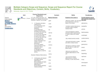
IntroductionMIMO1 IntroductionModern communications networks use MIMO technology to achieve high data rates.As a special MIMO technique, beamforming also permits targeted illumination ofspecific areas, making it possible to improve transmission to users at the far reaches ofTMcell coverage. Like other communications standards such as WLAN and WiMAX ,LTE also defines beamforming. Beamforming is particularly important for the timedivision duplex (TDD) mode in LTE. This white paper describes the available tendownlink and two uplink transmission modes (TM) in LTE as specified in 3GPPRelease 12, as well as how beamforming is used in LTE.2 MIMO and Beamforming Technologies2.1 MIMOThis paper discusses the MIMO concepts only to the extent that they apply to LTEtransmission modes (see 3.2). Refer to [3] for a more detailed description of the MIMOconcept as well as for a look at how MIMO is used in various communications systems.MIMO systems are used to improve the robustness of data transmission or to increasedata rates. Typically, a MIMO system consists of m transmit antennas and n receiveantennas (Figure 1).Figure 1: MIMO system with m TX and n RX antennas1MA186 2eRohde & Schwarz LTE Beamforming 3
MIMO and Beamforming TechnologiesBeamforming basicsSimply stated, the receiver receives the signal y that results when the input signalvector x is multiplied by the transmission matrix H.y H*xTransmission matrix H contains the channel impulse responses hnm, which referencethe channel between the transmit antenna m and the receive antenna n.Many MIMO algorithms are based on the analysis of transmission matrix Hcharacteristics. The rank (of the channel matrix) defines the number of linearlyindependent rows or columns in H. It indicates how many independent data streams(layers) can be transmitted simultaneously. Increasing the robustness of data transmission – transmit diversityWhen the same data is transmitted redundantly over more than one transmitantenna, this is called TX diversity. This increases the signal-to-noise ratio. Spacetime codes are used to generate a redundant signal. Alamouti developed the firstcodes for two antennas. Today, different codes are available for more than twoantennas. Increasing the data rate – spatial multiplexingSpatial multiplexing increases the data rate. Data is divided into separate streams,which are then transmitted simultaneously over the same air interface resources.The transmission includes special sections (also called pilots or reference signals)that are also known to the receiver. The receiver can perform a channel estimationfor each transmit antenna’s signal. In the closed-loop method, the receiver reportsthe channel status to the transmitter via a special feedback channel. This enablesfast reactions to changing channel circumstances, e.g. adaptation of the number ofmultiplexed streams.When the data rate is to be increased for a single user equipment (UE), this is calledSingle User MIMO (SU-MIMO). When the individual streams are assigned to varioususers, this is called Multi User MIMO (MU-MIMO)2.2 Beamforming basicsBeamforming uses multiple antennas to control the direction of a wavefront byappropriately weighting the magnitude and phase of individual antenna signals(transmit beamforming). For example this makes it possible to provide better coverageto specific areas along the edges of cells. Because every single antenna in the arraymakes a contribution to the steered signal, an array gain (also called beamforminggain) is achieved.1MA186 2eRohde & Schwarz LTE Beamforming 4
MIMO and Beamforming TechnologiesBeamforming basicsReceive beamforming makes it possible to determine the direction that the wavefrontwill arrive (direction of arrival, or DoA). It is also possible to suppress selectedinterfering signals by applying a beam pattern null in the direction of the interferingsignal.Adaptive beamforming refers to the technique of continually applying beamforming to amoving receiver. This requires rapid signal processing and powerful algorithms.Figure 2: Antenna array with a distance d between the individual antennas. The additional path that awavefront must traverse between two antennas is d * sin θ.As seen in Figure 2, the wavefront of a signal must traverse the additional distanced * sin θ to the next antenna. Using the speed of light c, it is possible to calculate thedelay between the antennas.(i 1)d sin (i 1) cd sin c i The signal si at each antenna is:This approximation is valid only for narrowband signals.1MA186 2eRohde & Schwarz LTE Beamforming 5
MIMO and Beamforming TechnologiesBeamforming basicsWritten as a vector: 1 e j e j 2 s(t) j 3 ·s(t) a( )·s(t), e j ( M 1) e where a is the array steering vector.Figure 3 shows an example of the amplitude response of an antenna array with eightelements (uniform linear array, ULA) versus the angle . In this example, the maximumis obtained when a signal coming from the boresight direction ( 0) impinges on thearray.Figure 3: Beampattern example of an 8-element ULABeamforming is made possible by weighting the magnitude and/or phase of the signalat the individual antennas:Hy(t) w · a( ) · s(t),where w is the weight vector. The signals are weighted so that they can be addedconstructively in the direction of an intended transmitter/receiver, and destructively inthe direction of interferers.1MA186 2eRohde & Schwarz LTE Beamforming 6
MIMO and Beamforming TechnologiesBeamforming basicsBecause beamforming is intended to provide the best signal possible to a UE at aspecific location, finding the weight vector w is an essential step. Two basic methodsfor finding the weight vector can be used which also affects the arrangement of theantenna array. The distance d between the antennas is a critical factor as well.Determining the weighting using DoAIf the position of the UE is known, the beamforming weightings can be adaptedaccordingly to optimize transmission for this UE. Therefore, specialized algorithms,such as MUSIC [4] or ESPRIT [5]), could be used in the base station to determine theDoA for the UE signal, and thus to determine its location. A uniform linear array (ULA)antenna array is typically used, where the distance d between the individual antennasis the same and d λ/2. This type of array can be seen as a spatial filtering andsampling in the signal space. Just as the Nyquist criterion applies to sampling a signalover time, the distance here must be d λ/2 in order to determine the DoA.Determining the weighting using channel estimationOther algorithms determine the optimum beamforming weighting from a channelestimation; for example, by using existing training sequences. In a TDD system, uplinkand downlink are on the same frequency and thus the channel characteristics are thesame. That is why a feedback is not needed from the UE when a suitable uplink signalis present that the base station can use to estimate the channel. In the case of TDLTE, the uplink sounding reference signal can be used.Figure 4 shows how the distance between the antenna elements affects the antennacharacteristics, based on a simple example of a two-element array. With increasingdistance between the antenna elements, the side lobes are increasing.Figure 4: The antenna diagram is affected by the distance d between the antennas. In this example, dis 10 %, 30 %, and 50 % greater than λ/2. (CBI 0 refers to code book index 0, see chapter 3.2.4)1MA186 2eRohde & Schwarz LTE Beamforming 7
MIMO and Beamforming TechnologiesBase Station Antennas2.3 Base Station AntennasAs described in the above section, the geometric characteristics of the antenna arraysignificantly affect the radiation characteristics. This is discussed here using theexample of conventional base station antennas.At present, conventional passive base station antennas are typically made up ofmultiple cross-polarized elements. In the y-axis, multiple elements are combined inorder to set the illumination (cell radius). All elements that have the same polarityradiate the same signal (shown in color at the left antenna of Figure 5). Especiallyrelevant for MIMO and beamforming is the arrangement of the cross-polarizedelements and the columns in the x-axis.The antenna at the left consists of two elements arranged at 90 to each other (crosspolarized). Each "polarization column" (blue or red) represents an antenna elementthat can transmit a different signal. This makes it possible to transmit two signals with acompact antenna arrangement, such as for 2x2 MIMO or TX diversity. Analogously,the antenna at the middle can radiate four independent signals (4xN MIMO), while theantenna at the right can radiate eight independent signals (8xN MIMO).The antennas shown in Figure 5 could also be used for beamforming. However,beamforming requires correlated channels; that is, elements with the same polarization( 45 or –45 ) must be used. Also the distance between the columns should not be toolarge. Beamforming could be carried out with two antenna elements (columns with thesame polarization) in the antenna layout in the middle, or with four antenna elements inthe layout on the right.Base station antenna architectures are currently evolving. Active antennas are animportant trend that allow seamless integration of beamforming concepts, e.g. byimplementing dedicated transceivers for the required number of antenna elements.Figure 5: Various cross-polarized base station antenna arrays for MIMO and beamforming.1MA186 2eRohde & Schwarz LTE Beamforming 8
Transmission modes and Beamforming in LTEBrief overview of LTE3 Transmission modes and Beamforming inLTE3.1 Brief overview of LTEA complete description of LTE is found in [2] for LTE-A in [9] and [10]. This white paperprovides just a brief overview.3.1.1 Physical Channels and SignalsLTE defines a number of channels in the downlink as well as the uplink. Table 1 andTable 2 provide an overview.DownlinkLTE downlink physical channelsNamePurposeCommentPDSCHPhysical downlink shared channeluser dataPDCCHPhysical downlink control channelcontrol informationPCFICHPhysical control format indicator channelindicates format of PDCCHPHICHPhysical hybrid ARQ indicator channelACK/NACK for uplink dataPBCHPhysical broadcast channelinformation during cell searchLTE downlink physical signalsRSPrimary and secondary synchronization signalinformation during cell searchReference signalsenables channel estimationTable 1: Overview of LTE downlink physical channels and signalsUplinkLTE uplink physical channelsNamePurposeCommentPUSCHPhysical uplink shared channeluser dataPUCCHPhysical uplink control channelcontrol informationPRACHPhysical random access channelpreamble transmissionLTE uplink physical signalsDRSDemodulation reference signalchannel estimation and demodulationSRSSounding reference signaluplink channel quality evaluationTable 2: Overview of LTE uplink physical channels and signals1MA186 2eRohde & Schwarz LTE Beamforming 9
Transmission modes and Beamforming in LTEBrief overview of LTE3.1.2 Downlink reference signal structureThe downlink reference signal structure is important for channel estimation. It definesthe principle signal structure for 1-antenna, 2-antenna, and 4-antenna transmission.Specific pre-defined resource elements (indicated by R0-3) in the time-frequencydomain carry the cell-specific reference signal sequence. One resource elementrepresents the combination of one OFDM symbol in the time domain and onesubcarrier in the frequency domain. Figure 6 shows the principle of the downlink cellspecific reference signal structure for 1 antenna and 2 antenna transmission. Thesereference signals are used for modes like spatial multiplexing or transmit diversity withup to four antennas.Figure 6: Distribution of the downlink cell specific reference signals in LTE; see top for one antennaand bottom for two antennas. [1]A different pattern is used for beamforming (see section 3.2.7). UE-specific referencesignals are used here. These are needed because whenever beamforming is used, thephysical downlink shared channel for each UE is sent with a different beamformingweighting. The UE-specific reference signals and the data on the PDSCH for a UE aretransmitted with the same beamforming weighting.LTE TDD UEs must (mandatory) support UE-specific reference signals, while it isoptional for LTE FDD UEs. Beamforming is of particular interest for LTE TDD becausethe same frequency is used in the downlink and uplink.1MA186 2eRohde & Schwarz LTE Beamforming 10
Transmission modes and Beamforming in LTEFigure 7: Distribution of reference signals for transmission mode 7 [1]In TM 8 also UE-specific reference signals (RS) are used. Since the same elementsare used for both streams, the reference signals must be coded differently so that theUE can distinguish among them. Figure 15 in section 3.2.8 shows the position of theRS in TM8.TM 9 and TM10 also use UE-specific reference signals (RS). Here again the sameelements are used for different streams, the reference signals must be codeddifferently so that the UE can distinguish among them (see 3.2.9).3.2 Transmission modes (TM) in LTE downlinkIn the downlink, LTE uses technologies such as MIMO to achieve high data rates;however, it also offers fallback technologies such as transmit diversity or SISO. In theRelease 9 specification [1], up to four antennas are defined in the base station and upto four antennas in the UE.Since Release 10 up to eight antennas are possible in the downlink.Beamforming is also supported. However, in this case the number of base stationantennas is not specified; it depends on the implementation.Figure 8: Block diagram of LTE transmission. One or two code words are mapped to one to fourlayers. The layers are then applied to one to eight antenna ports.1MA186 2eRohde & Schwarz LTE Beamforming 11
Transmission modes and Beamforming in LTETransmission modes (TM) in LTE downlinkThe various scenarios for the downlink are reflected in the different transmissionmodes (TMs). Release 12 describes ten different TMs, which are explained below. SeeTable 3 for an overview.Downlink Transmission modes in LTE Release 12DCITransmissionmodesDescription1Single transmit antenna1/1Asingle antenna portport 02Transmit diversity1/1A2 or 4 antennasports 0,1 ( 3)3Open loop spatial multiplexing withcyclic delay diversity (CDD)2A2 or 4 antennasports 0,1 ( 3)4Closed loop spatial multiplexing22 or 4 antennasports 0,1 ( 3)5Multi-user MIMO1D2 or 4 antennasports 0,1 ( 3)6Closed loop spatial multiplexingusing a single transmission layer1B1 layer (rank 1),2 or 4 antennasports 0,1 ( 3)(Main)Comment7Beamforming1single antenna port, port 5(virtual antenna port, actualantenna configurationdepends on implementation)8Dual-layer beamforming2Bdual-layer transmission,antenna ports 7 and 898 layer transmission2CUp to 8 layers,antenna ports 7 - 14108 layer transmission2DUp to 8 layers,antenna ports 7 - 14Table 3: Overview of the ten downlink transmission modes in LTE Release 12.3.2.1 TM 1 – Single transmit antennaThis mode uses only one transmit antenna.3.2.2 TM 2 – Transmit diversityTransmit diversity is the default MIMO mode. It sends the same information via variousantennas, whereby each antenna stream uses different coding and different frequencyresources. This improves the signal-to-noise ratio and makes transmission morerobust.In LTE, transmit diversity is used as a fallback option for some transmission modes,such as when spatial multiplexing (SM) cannot be used. Control channels, such asPBCH and PDCCH, are also transmitted using transmit diversity.1MA186 2eRohde & Schwarz LTE Beamforming 12
Transmission modes and Beamforming in LTETransmission modes (TM) in LTE downlinkFor two antennas, a frequency-based version of the Alamouti codes (space frequencyblock code, SFBC) is used, while for four antennas, a combination of SFBC andfrequency switched transmit diversity (FSTD) is used.3.2.3 TM 3 – Open loop spatial multiplexing with CDDThis mode supports spatial multiplexing of two to four layers that are multiplexed to twoto four antennas, respectively, in order to achieve higher data rates. It requires less UEfeedback regarding the channel situation (no precoding matrix indicator is included),and is used when channel information is missing or when the channel rapidly changes,e.g. for UEs moving with high velocity.In addition to the precoding as defined in Table 4, the signal is supplied to everyantenna with a specific delay (cyclic delay diversity, or CDD), thus artificially creatingfrequency diversity.Figure 9: TM 3: Spatial multiplexing with CDD; the individual
MIMO and Beamforming Technologies Beamforming basics 1MA186_2e Rohde & Schwarz LTE Beamforming 6 Written as a vector: s(t) ·s(t) a( )·s(t), where a is the array steering vector. Figure 3 shows an example