Transcription
User GuideAudio ProductsMixers and ProcessorsAXI 22 AT and AXI 44 ATAudio Expansion Interfaces68-2972-01 Rev. E06 21
Copyright 2017-2021 Extron. All rights reserved. www.extron.comTrademarksAll trademarks mentioned in this guide are the properties of their respective owners.The following registered trademarks ( ), registered service marks (SM), and trademarks (TM) are the property of RGB Systems, Inc. or Extron (see thecurrent list of trademarks on the Terms of Use page at www.extron.com):Registered Trademarks ( )Extron, Cable Cubby, ControlScript, CrossPoint, DTP, eBUS, EDID Manager, EDID Minder, eLink, Flat Field, FlexOS, Glitch Free, Global Configurator,Global Scripter, GlobalViewer, Hideaway, HyperLane, IP Intercom, IP Link, Key Minder, LinkLicense, LockIt, MediaLink, MediaPort, NAV,NetPA, PlenumVault, PoleVault, PowerCage, PURE3, Quantum, ShareLink, Show Me, SoundField, SpeedMount, SpeedSwitch, StudioStation,System INTEGRATOR, TeamWork, TouchLink, V‑Lock, VideoLounge, VN‑Matrix, VoiceLift, WallVault, WindoWall, XPA, XTP, XTP Systems, and ZipClipRegistered Service Mark(SM) : S3 Service Support SolutionsTrademarks ( )AAP, AFL (Accu‑RATE Frame Lock), ADSP (Advanced Digital Sync Processing), AVEdge, CableCover, CDRS (Class D Ripple Suppression),Codec Connect, DDSP (Digital Display Sync Processing), DMI (Dynamic Motion Interpolation), Driver Configurator, DSP Configurator, DSVP (DigitalSync Validation Processing), EQIP, Everlast, FastBite, Flex55, FOX, FOXBOX, IP Intercom HelpDesk, MAAP, MicroDigital, Opti‑Torque,PendantConnect, ProDSP, QS‑FPC (QuickSwitch Front Panel Controller), Room Agent, Scope‑Trigger, SIS, Simple Instruction Set, Skew‑Free,SpeedNav, Triple‑Action Switching, True4K, True8K, Vector 4K, WebShare, XTRA, and ZipCaddy
FCC Class A NoticeThis equipment has been tested and found to comply with the limits for a Class A digitaldevice, pursuant to part 15 of the FCC rules. The Class A limits provide reasonableprotection against harmful interference when the equipment is operated in a commercialenvironment. This equipment generates, uses, and can radiate radio frequency energy and,if not installed and used in accordance with the instruction manual, may cause harmfulinterference to radio communications. Operation of this equipment in a residential area islikely to cause interference. This interference must be corrected at the expense of the user.Conventions Used in this GuideNotificationsThe following notifications are used in this guide:WARNING:Potential risk of severe injury or death.AVERTISSEMENT : Risque potentiel de blessure grave ou de mort.ATTENTION: Risk of property damage. Risque de dommages matériels.NOTE: A note draws attention to important information.TIP:A tip provides a suggestion to make working with the application easier.Software CommandsCommands are written in the fonts shown here: AR Merge Scene,,0p1 scene 1,1 B 51 W C.0[01] R 0004 00300 00400 00800 00600 [02] 35 [17] [03]E X! *X1&* X2)* X2#* X2! CE}NOTE: For commands and examples of computer or device responses used in thisguide, the character “0” is the number zero and “O” is the capital letter “o.”Computer responses and directory paths that do not have variables are written in the fontshown here:Reply from 208.132.180.48: bytes 32 times 2ms TTL 32C:\Program Files\ExtronVariables are written in slanted form as shown here:ping xxx.xxx.xxx.xxx —tSOH R Data STX Command ETB ETXSelectable items, such as menu names, menu options, buttons, tabs, and field names arewritten in the font shown here:From the File menu, select New.Click the OK button.Specifications AvailabilityProduct specifications are available on the Extron website, www.extron.com.Extron Glossary of TermsA glossary of terms is available at https://www.extron.com/technology/glossary.aspx.
ContentsIntroduction. 1Dante Controller. 19About this Guide. 1About the AXI 22 AT and AXI 44 AT. 1Features. 2Applications Diagrams. 3Downloading and Installing Dante Controller. 19Configuring the AXI in Dante Controller. 19Device Name. 20Receiver and Transmitter Names. 20Dante Controller Naming Conventions. 20Renaming the AXI 22 AT or AXI 44 AT inDante Controller. 20Renaming a Receiver or Transmitter. 22Finding a Dante Device IP Address. 24Identifying a Physical Dante Device. 25Physical Dante Network Setup. 25Dante Controller Operation. 26Dante Transmitters and Receivers. 26Routing Device Channels. 26Disconnecting Inputs from Outputs. 28Dante Troubleshooting. 28Simplifying the Network for Troubleshooting. 28Troubleshooting the Network Interface. 28Restarting Dante Controller. 29Installation and Operation. 4Mounting. 4Rear Panel Connections. 5Front Panel Controls. 8Reset Modes. 9Reset Mode 1. 9Reset Mode 2. 9DSP Configurator Software. 10Downloading and Installing DSP ConfiguratorSoftware. 10Accessing the DSP Configurator Help File. 10DSP Configurator Software Workspace. 11Menu Bar. 11File. 11Edit. 12View. 12Tools. 13Window. 13Help. 14Presets. 14Live and Emulate Panel. 14Connecting Live to a Device. 15Disconnecting from a Device. 16Mic/Line Inputs. 17Renaming AT Outputs. 17Mic/Line Gain Dialog Box. 17Analog Outputs. 18Renaming AT Inputs. 18Attenuation Dialog Box. 18Remote Control. 30SIS Commands. 30Using the Command and Response Tables. 30Verbose Mode. 31Symbol Definitions. 31Error Responses. 31Command and Response Table for SISCommands. 32DSP SIS Commands. 34Command and Response Table for DSP SISCommands. 35Object ID (OID) Number and Value RangeTables. 35Technical Publications Standards and Styles Contentsv
Technical Publications Standards and Styles Contentsvi
IntroductionThis section provides an overview of this guide and the features of the Extron AXI 22 AT andAXI 44 AT audio expansion interfaces. This section covers the following topics: About this Guide About the AXI 22 AT and AXI 44 AT Features Applications DiagramsAbout this GuideThis guide contains installation, configuration, and operation information for the ExtronElectronics AXI 22 AT and AXI 44 AT audio expansion interfaces. In this guide, the terms“AXI devices,” “device,” and “AXI” are all used to refer to the AXI 22 AT and AXI 44 ATinterchangeably.About the AXI 22 AT and AXI 44 ATThe AXI 22 AT and AXI 44 AT audio expansion interfaces are analog-to-Dante/Dante-toanalog converters in 1U high, quarter rack width enclosures. The AXI 22 AT is a two input,two output interface and the AXI 44 AT is a four input, four output interface. The inputsfor both devices include preamps with 48 V phantom power and accept 3.5 mm captivescrew connectors. The Dante port on the rear panel of each device provides 2x2 and 4x4Dante interfacing respectively. Gain and phantom power settings are software controlledand can be made from the front panel, DSP Configurator Software, or SIS commandsvia DataViewer. The AXI will appear on the Dante network and use the Dante Controllersoftware for routing, device naming, channel naming, transmission latency, sample rate,and IP communication settings. The AXI 22 AT and AXI 44 AT are pure break-in/break-outdevices that contain no DSP processing.AXI 22 AT and AXI 44 AT Introduction1
Features Two or four mic/line inputs transmit audio to a Dante network — Two(AXI 22 AT) or four (AXI 44 AT) mic/line inputs include selectable 48 volt phantompower for balanced or unbalanced sources and accept 3.5 mm 6-pole captive screwconnectors. A rotary detented knob is available for gain control. Two or four line level outputs receive audio from a Dante network —Two(AXI 22 AT) or four (AXI 44 AT) channels of high quality digital audio can be routed fromlocal or remote systems via Dante and converted to balanced or unbalanced line levelanalog audio and output with 3.5 mm 6-pole captive screw connectors. Input select, gain, and phantom power controls located on front panel andconfigurable through DSP Configurator Software — Settings can be modifiedfrom the front panel, DSP Configurator Software, or SIS commands via DataViewer. Dante audio networking provides a wide range of expansion options — Danteequipped audio products, including the AXI 22 AT and AXI 44 AT, provide scalabilityfor creating larger audio systems over a local area network using standard Internetprotocols. Studio grade 24-bit analog-to-digital and digital-to-analog converters withselectable sampling rates up to 96 kHz — Professional converters fully preserve theintegrity of the original audio signal, with selectable sampling rates via Dante Controller. Power over Ethernet allows the AXI 22 AT and AXI 44 AT to receive power overa single Ethernet cable, eliminating the need for a local power supply. 1U, quarter rack width metal enclosure — Compact, durable enclosure can bediscreetly installed under a desk, in a lectern, in millwork, or in an AV equipment rack. Highly reliable, energy-efficient external universal power supply (optional).AXI 22 AT and AXI 44 AT Introduction2
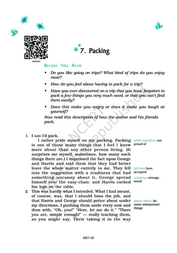
Applications DiagramsBreakout Table #1Breakout Table #2MicrophonesMicrophonesExtronSM 3SurfaceMountSpeakersAudioPOWER12V--A MAXMIC / LINE phonesExtronSM 3SurfaceMountSpeakersExtronAudioAT (PoE)Breakout Table #8TREBLEPOWER12V--A MAXMIC / LINE INSMIC / LINE INSExtronAudioAT (PoE)LEVELSTEREORBASSDUALMONOPOWER12V--A MAXMIC / LINE INSAudioAT (PoE)OUTPUTSExtronLEVELSTEREOBASSDUALMONOMPA 152 PlusMINI POWER AMPLIFIERExtronMPA 152 PlusExtronAXI 22 ATExtronMPA 152 PlusExtronAXI 22 ATStereo AmplifierAudio ExpansionInterface withDanteTREBLERMINI POWER AMPLIFIERStereo AmplifierAudio ExpansionInterface withDanteTREBLEExtronMPA 152 PlusMINI POWER AMPLIFIERExtronMPA 152 PlusExtronAXI 22 ATSurfaceMountSpeakersExtronAudioMPA 152 PlusExtronSM 3Stereo AmplifierAudio ExpansionInterface IGNALSIGNALOUTPUTS2345678DMP 128 PlusDIGITAL MATRIX PROCESSORExtronDMP 128 Plus C ATDigital Matrix 567891011121CLIPCLIPSIGNALSIGNALOUTPUTS2345678DMP 128 PlusDIGITAL MATRIX PROCESSORExtronDMP 128 Plus C ATDigital Matrix ProcessorFigure 1.AXI 22 AT Application DiagramLecternExtronSF 3CT LPMicrophonesWirelessMic ReceiverSpeakerPOWER12V0.7A MAXINPUTSSIGLINKAUDIOPOWER12V0.7A MAXIRTx Rx G Tx RxExtronDTP HDMI4K 230 TxMP33PlayerSIGCATx Cableup to 230'(70 m)LINKDisplayHDMIOUTPUTSLAUDIORDTP IN100-240V --A MAXOUT1 CONFIGURABLE2HDMI3HDMI4HDMI1ININPUT50-60 HzTransmitterAudioFLAT PANELReceiverOVER DTPRS-232DTP OUTAudioExtronDTP HDMI4K 230 RxHDMIAudioMODEL 8012LRLRHDMI23ExtronIN1604 HD4 VTALLY OUTHDMICONTACT IN1AUDIOOUTPUT23RS-2324 GTx Rx GREMOTEFour InputScalerAudio100-240VXPA 2001-70V0.5A, 50-60HzATTENUATIONINPUTSHPFMIC / LINE INPUTSOUTPUTSGOFFV12345678IN G O1 O2IN G O1 O2IN G O1 O2IN G O1 O2IN G O1 O2IN G O1 O2IN G O1 O2IN G O1 O21291011126782345678AT1ACP5 V S -S GREMOTEINPUTS450 - 60 HzAudio ExpansionInterface with Dante(SEC)23(PRI)USB AUDIORS-232Tx Rx G4RESETLANExtronDMP 128 Plus C ATDigital MatrixProcessorExtronACP 100Audio ControlPanelEthernetFigure 2.1DMP 128 Plus C AT3DMP EXP0.7A MAXI/O100-240VCLASS 2 WIRINGC GAudioAmplifierExtronAXI 44 AT50mAL (SUMMED) R80 HzExtronXPA 2001-70VBlu-ray PlayerROUTPUTSPOWER12V--A MAXSIGNAL70 V OUTPUTREMOTE10V12 10 8614184226 0LIMITER/PROTECTAT #2VOLUMESOURCE#3MUTEExtronEthernetAXI 44 AT Application DiagramAXI 22 AT and AXI 44 AT Introduction3
Installation and OperationThis section describes the AXI 22 AT and AXI 44 AT rear panel connections and front panelcontrols. The following topics are covered: Mounting Rear Panel Connections Front Panel Controls Reset ModesMountingThe 1U high, quarter rack width, 6 inch deep AXI 22 AT and AXI 44 AT devices mount in thefollowing manners:Rack mounting — Attach the device to a standard 19 inch rack shelf. The followingUnderwriters Laboratories (UL) guidelines pertain to the installation of the AXI 22 AT andAXI 44 AT devices in a rack: Reduced air flow — Install the equipment in the rack so that the amount of airflow required for safe operation of the equipment is not compromised. Mechanical loading — Mount the equipment in the racks so that unevenmechanical loading does not create a hazardous condition. Circuit overloading — When connecting the equipment to the supply circuit,consider the effect that circuit overloading might have on overcurrent protectionand supply wiring. Consider equipment nameplate ratings when addressing thisconcern. Reliable earthing (grounding) — Maintain reliable grounding of rack-mountedequipment. Pay particular attention to power supply connections other than directconnections to the branch circuit (such as the use of power strips). Under-furniture mounting — Mount the AXI 22 AT or AXI 44 AT under the surface ofa desk, table, or podium. Free-standing — Attach the four rubber feet provided with the device to the bottom ofthe AXI 22 AT or AXI 44 AT in the four corners and place the unit on furniture as desired.NOTE: To mount the AXI 22 AT or AXI 44 AT using an Extron mounting kit, see theinstructions provided with the kit.AXI 22 AT and AXI 44 AT Installation and Operation4
12V0.5A MAX1AOUTPUTS12BAT (PoE)2CRDA 12 VDC Power InletB Mic/Line InputsC Line OutputsFigure 3.E12V0.6A MAX234A1234AT (PoE)BCRDED AT (PoE) PortE Reset ButtonAXI 22 AT and AXI 44 AT Rear Panel Connections12 VDC Power Inlet — As an alternative to PoE, the AXI devices can be powered withan optional 12 VDC power supply. Connect the power supply to the rear panel powerinlet with a captive screw connector. Plug the power cord into the IEC connector onthe power supply (see figure 4). The power LED on the front panel blinks as the unit ispowering on and lights steadily when the unit is ready for use.WARNING:The two power cord wires must be kept separate while thepower supply is plugged in. Remove power before wiring.AVERTISSEMENT : Les deux cordons d’alimentation doivent être tenus à l’écartl’un de l’autre quand l’alimentation est branchée. Couper l’alimentation avant defaire l’installation électrique.ATTENTION:Do not connect any external power supplies until you have read theAttention notifications on the next page.Ne branchez pas de sources d’alimentation externes avant d’avoir lu lesmises en garde de la page suivante.Rear PanelPower ReceptacleDC Power CordCaptive ScrewConnectorRidged– Return 12 VDC inputSmoothGroundall devices.100-240V50-60Hz1A MAXAPOWER1OUTPUTSMIC / LINE INSPOWERMIC / LINE INPUTSRear Panel ConnectionsFigure 4.ExternalPower Supply12 VDC, 1.5 A max.Rear Panel 12 VDC Power ConnectorAXI 22 AT and AXI 44 AT Installation and Operation5
ATTENTION: Always use a power supply provided by or specified by Extron. Use of anunauthorized power supply voids all regulatory compliance certification andmay cause damage to the supply and the end product. Utilisez toujours une source d’alimentation fournie ou recommandée parExtron. L’utilisation d’une source d’alimentation non autorisée annule touteconformité réglementaire et peut endommager la source d’alimentation ainsique le produit final. If not provided with a power supply, this product is intended to be suppliedby a UL Listed power source marked “Class 2” or “LPS” and rated output12Vdc 0.5 A minimum (for AXI 22 AT) or 12Vdc 0.6 A minimum (for AXI 44AT), or 48 VDC (PoE), minimum 0.35 A. Si ce produit n’est pas fourni avec une alimentation, il doit être utilisé avecune source d’alimentation certifiée UL de classe 2 ou LPS avec une tensionnominale 12 Vcc, 0,5 A minimum (pour l’AXI 22 AT) ou 12 Vcc, 0,6 Aminimum (pour l’AXI 44 AT), ou 48 Vcc (PoE), 0,35 A minimum. Extron power supplies are certified to UL/CSA 60950-1 and are classified asLPS (Limited Power Source). Use of a non-LPS or unlisted power supply willvoid all regulatory compliance certification. Les sources d’alimentation Extron sont qualifiées UL/CSA 60950-1 etsont classées LPS (Limited Power Source). L’utilisation d’une sourced’alimentation non-listée ou non-listée LPS annulera toute certification deconformité réglementaire. Unless otherwise stated, the AC/DC adapters are not suitable for use in airhandling spaces or in wall cavities. The power supply is to be located withinthe same vicinity as the Extron AV processing equipment in an ordinarylocation, Pollution Degree 2, secured to the equipment rack within thededicated closet, podium, or desk. Sauf mention contraire, les adaptateurs AC/DC ne sont pas appropriés pourune utilisation dans les espaces d’aération ou dans les cavités murales.La source d’alimentation doit être située à proximité de l’équipementde traitement audiovisuel dans un endroit ordinaire, avec un degré 2 depollution, fixé à un équipement de rack à l’intérieur d’un placard, d’uneestrade, ou d’un bureau. The installation must always be in accordance with the applicable provisionsof National Electrical Code ANSI/NFPA 70, article 725 and the CanadianElectrical Code part 1, section 16. Cette installation doit toujours être en accord avec les mesures qui s’appliqueau National Electrical Code ANSI/NFPA 70, article 725, et au CanadianElectrical Code, partie 1, section 16. The power supply shall not be permanently fixed to building structure orsimilar structure. La source d’alimentation ne devra pas être fixée de façon permanente à unestructure de bâtiment ou à une structure similaire.AXI 22 AT and AXI 44 AT Installation and Operation6
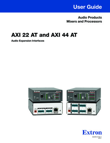
The length of the exposed wires in the stripping process is critical. The ideallength is 3/16 inches (5 mm). If the wires are any longer, the exposed wiresmay touch, causing a short circuit between them. If they are any shorter, thewires can be easily pulled out even if tightly fastened by the captive screws. La longueur des câbles exposés est primordiale lorsque l’on entreprend deles dénuder. La longueur idéale est de 5 mm (3/16 inches). S’ils sont un peuplus longs, les câbles exposés pourraient se toucher et provoquer un courtcircuit. S’ils sont un peu plus courts, ils pourraient sortir, même s’ils sontattachés par les vis captives.NOTE: Do not tin the wires. Tinned wire does not hold its shape and can becomeloose over time.BMic/Line Inputs — Connect two mono balanced or unbalanced microphone or linelevel sources (AXI 22 AT) or four mono balanced or unbalanced microphone or line levelsources (AXI 44 AT) using 6-pole 3.5 mm captive screw input connectors (see 3-poleAudio Input Wiring in figure 5). Phantom power is available on all inputs.Instead of two or four mono sources, one balanced or unbalanced stereo signal(AXI 22 AT) or two balanced or unbalanced stereo sources (AXI 44 AT) can beconnected using 6-pole captive screw connectors (see 6-pole Audio Input Wiring infigure 5).3"16TipSleeveJumperTipRingSleeveBalanced InputUnbalanced InputBalanced InputCUnbalanced Input6-pole Audio INPUT Wiring3-pole Audio INPUT WiringFigure ngSleeve(5 mm) MAX. (typ)3-pole and 6-pole Audio Input WiringLine Outputs — Connect two mono balanced or unbalanced line level devices(AXI 22 AT) or four mono balanced or unbalanced line level devices (AXI 44 AT) using6-pole 3.5 mm captive screw connectors (see 3-pole Audio Output Wiring in figure 6).Instead of two or four mono line level devices, one stereo device (AXI 22 AT) or twostereo devices (AXI 44 AT) can be connected using 6-pole captive screw connectors(see 6-pole Audio Output Wiring in figure 6).TipNO Ground HereSleeveTipNO Ground HereSleeveTipRingSleeveTipRingSleeveBalanced OutputUnbalanced Output6-pole Audio OUTPUT WiringFigure 6.DTipRingSleeveTipNO Ground HereSleeveBalanced OutputUnbalanced Output3-pole Audio OUTPUT Wiring6-pole and 3-pole Audio Output WiringAT (PoE) Port — Connect an Ethernet cable to this RJ-45 port to connect theAXI 22 AT or AXI 44 AT to a Dante network. This connector supports digital audiotransport (AT), communication with the Dante network, and power over Ethernet (PoE).AXI 22 AT and AXI 44 AT Installation and Operation7
ATTENTION: Power over Ethernet (PoE) is intended for indoor use only. It is to beconnected only to networks or circuits that are not routed to the outside plantor building. L’alimentation via Ethernet (PoE) est destinée à une utilisation en intérieuruniquement. Elle doit être connectée seulement à des réseaux ou des circuitsqui ne sont pas routés au réseau ou au bâtiment extérieur.NOTE: When using 88.2 kHz or 96 kHz sampling rates, the AXI 44 AT can onlytransmit two channels of audio and receive two channels of audio.EReset Button — Using a stylus or small screwdriver, press and release this buttonto reset the unit to factory defaults, including Dante settings such as device name, IPaddress, channel names, and audio format (see Reset Modes on page 9).Front Panel ControlsEHIEHIAXI 22 ATCONTROL2 48VGAINCBDPOWER12V0.5A MAXMIC / LINE INS12CLIP -1SIG -2CLIP -B134GGAIN2SIG -3CLIP -4SIG -AICBFGHIUSB Config PortInput Selector ButtonInput Indicator LEDsF4OUTPUTSGIPhantom Power SwitchPhantom Power Indicator LEDsInput and Output Signal and Clip LEDs212AT (PoE)AXI22 AT and AXI 44 AT FrontPanel ControlsPOWER12V0.6A MAX3Gain Rotary Encoder1Input Level and Gain LED StackD2ONOFFPower LED IndicatorFigure7.OUTPUTSINPUTS 48V11CLIP -OUTPUTSAT (PoE)23434LED Indicator — This green LED blinkswhilethe unitis poweringon and lightsA 1 PowerRsteadily when the unit is ready for use.AGAIN LEVEL 42 36 30 24 18 12 602CONFIGSIG -FABCDEINPUTONOFFA2OUTPUTS1CONFIG1MIC / LINE INPUTSGAIN LEVEL 42 36 30 24 18 12 60INPUTAXI 44 ATCONTROLINPUTSRBUSB Config Port — Connect a computer to this USB Mini-B port for deviceconfiguration.CInput Selector Button — Press this button to cycle through the device inputs. Selectan input to adjust gain, set phantom power, and read input levels for that input.DInput Indicator LEDs — These LEDs light to indicate which input is currently selected.Gain and phantom power adjustments are only applied to the currently selected input.CDEABCDAXI 22 AT and AXI 44 AT Installation and OperationE8
EInput Level and Gain LED Stack — The LED stack displays the input signal level ofthe selected input, from no signal to -60 dBFS (first LED lit) up to 0 dBFS (all LEDs lit).When the gain rotary encoder is rotated, the LED stack changes to display the inputgain level of the selected input. Input gain level continues to display for 2 seconds afteradjustment of the rotary encoder ceases. After this 2 second period, the LED stackdisplays the input signal level.The dB scale to the left of the LEDs indicates input gain level from 0 dB to 42 dB.Each LED represents 6 dB of gain, while gain adjustments are made in 3 dB steps.The LED will blink to indicate a 3 dB change in level, and light solid to indicate a 6 dBchange. The entire LED stack flashes to indicate the input is muted.FGain Rotary Encoder — The rotary encoder adjusts the input gain for the currentlyselected input, from 0 dB to 42 dB in 3 dB steps. Use a small flat head screwdriver,such as the provided Extron Tweeker, to turn the encoder clockwise to raise the gainand counter-clockwise to lower the gain.GPhantom Power Switch — This momentary switch turns 48 V phantom power onor off for the currently selected input. Use a small flat head screwdriver, such as theprovided Extron Tweeker to adjust the phantom power switch. Push the switch upto turn phantom power on and down to turn it off. The switch is neutral in the middleposition (default).HPhantom Power Indicator LEDs —These green LEDs light steadily to indicate whichchannels have phantom power applied.IInput and Output Signal and Clip LEDs — The green signal LEDs light steadilywhen signal is present and increase in intensity from -60 dBFS (lowest intensity, signalpresence indication) to -1 dBFS (full brightness). The red clip LEDs light steadily at-1 dBFS to indicate clipping and stay lit for one second beyond receiving the clipmessage.Reset ModesPressing the rear panel reset button (see figure 3, E on page 5) with a stylus orExtron Tweeker will reset only the Dante module in the AXI, leaving the gain and phantompower settings unaffected (see Command and Response Table for SIS Commands onpage 32 for information resetting gain and phantom power). There are two reset modesactivated with the rear panel reset button.Reset Mode 1Press the rear panel reset button and quickly release it to cause a hardware reset of theDante module while preserving all of its settings such as IP configuration, routing, devicename, channel names, and sampling rate.Reset Mode 2To cause an absolute system reset of the Dante module back to factory default conditions,press and hold the rear panel reset button for 10 seconds until the AT (PoE) port LEDs flash.Following this reset, the Dante module will proceed to its normal boot sequence. This resetwill: Set the IP configuration to default settings Clear all audio channel routing Set the Dante device name and channel names to defaultAXI 22 AT and AXI 44 AT Installation and Operation9
DSP ConfiguratorSoftwareIn addition to front panel hardware controls, the AXI 22 AT and AXI 44 AT can be configuredwith a PC running Microsoft Windows 7 or newer and Extron DSP Configurator Software.This section describes Extron DSP Configurator Software and covers the following topics: Downloading and Installing DSP ConfiguratorSoftware Menu Bar Accessing the DSP Configurator Help File Mic/Line Inputs DSP Configurator Software Workspace Analog OutputsDownloading and Installing DSP Configurator Software1. From www.extron.com, click the Download tab. The Download page opens.2. From the Download page, click Software.3. From the Software page, locate and select DSP Configurator to open theDSP Configurator product page.4. On the DSP Configurator Software page, click Download.5. From the Download Center page, DSP Configurator Software should begindownloading automatically. If it does not, select click here.NOTE: An Extron Insider account is required to download DSP ConfiguratorSoftware and other software available from the Extron website. Login or accountcreation may be required before the Download Center page appears.6. Select Run to run the DSP Configurator Software installer or select Save to save theinstall file to run at a later time.Accessing the DSP Configurator Help FileDSP Configurator Software comes loaded with a context-sensitive help file that canbe accessed by clicking the help icon () in the top right corner of any dialog box inDSP Configurator. Alternatively, click Help Contents in the menu bar at the top ofthe main workspace, or press F1 on your keyboard. This help file contains detailedprocedures and further instruction on using all DSP Configurator Software features.AXI 22 AT and AXI 44 AT DSP Configurator Software10
DSP Configurator Software WorkspaceThe DSP Configurator Software workspace for the AXI 22 AT and AXI 44 AT containsa menu bar for accessing configuration tools and the main audio workspace for audioconfiguration (see figure 8).Figure 8.DSP Configurator Software WorkspaceMenu BarFile12New — Opens a new configuration file. If the currentconfiguration has not been saved, the Save dialogbox opens and asks to save the current configurationbefore the new configuration is opened. Click Yesto save the current configuration before opening thenew one. Click No to delete the current configurationbefore opening the new one. Click Cancel to returnto the current configuration.Open — Opens an existing configuration or templatefile. When selected, the Browse dialog box opensto search for saved configuration or template files.Double‑click a configuration or templat
dmp 128 plus level bass treble mini power amplifier mpa 152 plus stereo dual mono level bass treble mini power amplifier mpa 152 plus stereo dual mono level bass treble mpa 152 plus stereo mono figure 1. axi 22 at application diagram lr power 12v 0.7a max audio sig link dtp in outputs audio inputs over dtp rs-232 ir tx rxg power 12v 0.7a max .